IYF2CHFM100-27RADIO CONTROL SYSTEM
Hobbico Inc
Click to zoom
Application Details
- Equipment Class
- DXX - Part 15 Low Power Communication Device Transmitter
- Date of Grant
- Jul 26, 2007
- Application Purpose
- Original Equipment
- Date of Application
- Jul 26, 2007
- Equipment Note
- RADIO CONTROL SYSTEM
- Frequency Range
- 27.04500000 - 27.19500000
- Company
- Hobbico Inc
- Country
- United States
Documents & Files
Document Text
Text extracted from the exhibit documents filed with the FCC. Open a document above to read the original.
Users Manual
T2-27F-W Radio Controller Instruction Manual 1. Summarize of circuit The T2-27F-W controller is made up with High-Frequency (HF short for as follows) circuit and Low-Frequency (LF short for as follows) circuit. Separately, the HF part include RF Oscillation, RF Amplifier, Power Amplifier and Matched Impedance Antenna circuit, and Modulation Signal Source, Shaping circuit are included in the LF part. The controller has 2 sticks, the left for controlling the fly speed and altitude, total 4 levels. The right stick is for controlling the direction to turn left or right. 2. Electronic Specification z Operation Frequency:27.045Mhz and 27.195Mhz z Operation Mode:FM z Modulation Degree: KHz (=Standard Frequency) z Output Power:≤250Mw z Operation Voltage:9 V z Operation Current:<50mA 3. Using Guide 3.1 Installing 8 cells “AA” size Nicd or NiNH batteries into the battery case of controller. 3.2 Pull the antenna out, the Green light will glow. Handle the stick, and then the controller is ready to work. 3.3 Turn off both the airplane and controller. Pull out the charger cord from the back of the controller; gently plug the charge cord into he airplane, then turn on the controller, both the Green and Red lights glow. Charging is complete 15 minutes later when the Red light gets out. 3.4 When the Green light getting dark, the controller range will reduce distinct, now need exchange the battery soon. 3.5 Please note the attached top and bottom views about the controller. Remark: The antenna is permanently attached. This device complies with Part 15 of the FCC Rules. Operation is subject to the following two conditions: (1) this device may not cause harmful interference, and (2) this device must accept any interference received, including interference that may cause undesired operation. FCC NOTE: The manufacturer is not responsible for any radio or TV interference caused by unauthorized modifications to this equipment. Such modifications could void the user's authority to operate the equipment.
Block Diagram
FM 27.045MHz or 27. 195MHz Codin & modulate circuit Plezoelectric oscillator RF amplifier Power amplifier Regulator Charge circuit 9V battery pack
External Photos
EUT - Front View EUT - Back View
ID Label/Location Info
FCC ID Label Sample for Model: T2-27F-W FCC ID: IYF2CHFM100-27 This device complies with Part 15 of the FCC Rules. Operation is subject to the following two conditions: (1)this device may not cause harmful interference, and (2)this device must accept any interference received, including interference that may cause undesired operation.
ID Label/Location Info
FCC ID Label This device complies with Part 15 of the FCC Rules. Operation is subject to the following two conditions: (1)this device may not cause harmful interference, and (2) this device must accept any interference received, including interference that may cause undesired operation. The Label must not be a stick-on paper. The Label on these products must be permanently affixed to the product and readily visible at the time of purchase and must last the expected lifetime of the equipment not be readily detachable. Proposed Label Location on EUT EUT Bottom View/proposed FCC Mark Location FCC ID: IYF2CHFM100-27 This device complies with Part 15 of the FCC Rules. Operation is subject to the following two conditions:
Internal Photos
PCB- Front View PCB- Back View
Operational Description
T2-72F controller Adjusting Progress There are two steps to adjust up the controller. 1. PCB testing 1.1 Adjust the line loops L2, T1 and T2 on the PCB of controller, to observe the carrier wave is over 3.5V. The loading of the PCB is, The controller operate voltage is 9.5V and the normal operate current is 300 MA. 1.2 Need 2 pcs 50mAh Lipo batteries, charge one at 4.18-4.2V and the other is charged at 3.2-3.5V. Install the 4.2V battery on the charger, the red light does not flash, and the current get down to 5MA. When installing the 3.5V battery on the charger, the red light get on and the current will be 200MA. 2. check the entire controller 2.1 Install 6 cells alkalescence batteries on the controller and keep it 1m away from the spectrum analyzer, when the controller working, the signal intensity the spectrum analyzer get not less than dBm. 2.2 Use the controller to testing fly the model airplane Gain the flying altitude by moving the controller’s throttle (left) stick upward, it has 4 levels from bottom to top, it is meaning the motor will run with 4 different speeds. With moving the controller’s rudder (right) stick to left and right to make the airplane left and right turning.
Test Report
FCC TEST REPORT Page 1 of 25 FCC ID : IYF2CHFM100-27 Applicant : Hobbico Inc. 2904 Reasarch Road, champaign, ILLinois 61826-9021 America Equipment Under Test (EUT) : Product description : Radio control system Model No. : T2-27F-W Operation Frequency : 27.045MHz and 27.195MHz Operation Mode : FM Standards : FCC 15 Subpart C Paragraph 15.227 Date of Test : July 25, 2007 Test Engineer : Tiger Su Reviewed By : PERPARED BY: Waltek Services (Shenzhen) Co., Ltd. 8C,West Tower, Aidi Building, No.5003 Binhe Rd, Futian District, Shenzhen518045, Guangdong, China. Tel: 86-755-83551033 Fax: 86-755-83552400 Hobbico Inc. FCC ID: IYF2CHFM100-27 Page 2 of 25 2 Contents Page 1 COVER PAGE..........................................................................................................................................................1 2 CONTENTS ..............................................................................................................................................................2 3 TEST SUMMARY....................................................................................................................................................5 4 GENERAL INFORMATION..................................................................................................................................6 4.1 CLIENT INFORMATION............................................................................................................................................6 4.2 GENERAL DESCRIPTION OF E.U.T...........................................................................................................................6 4.3 DETAILS OF E.U.T. .................................................................................................................................................6 4.4 DESCRIPTION OF SUPPORT UNITS...........................................................................................................................6 4.5 STANDARDS APPLICABLE FOR TESTING..................................................................................................................6 4.6 TEST FACILITY........................................................................................................................................................7 4.7 TEST LOCATION......................................................................................................................................................7 5 EQUIPMENT USED DURING TEST ...................................................................................................................8 6 CONDUCTED EMISSION TEST ........................................................................................................................10 6.1 TEST EQUIPMENT..................................................................................................................................................10 6.2 TEST PROCEDURE.................................................................................................................................................10 6.3 CONDUCTED TEST SETUP.....................................................................................................................................11 6.4 EUT OPERATING CONDITION...............................................................................................................................11 6.5 CONDUCTED EMISSION LIMITS.............................................................................................................................12 6.6 CONDUCTED EMISSION TEST RESULT...................................................................................................................12 7 RADIATION EMISSION TEST...........................................................................................................................13 7.1 TEST EQUIPMENT..................................................................................................................................................13 7.2 MEASUREMENT UNCERTAINTY.............................................................................................................................13 7.3 TEST PROCEDURE.................................................................................................................................................13 7.4 RADIATED TEST SETUP.........................................................................................................................................14 7.5 SPECTRUM ANALYZER SETUP...............................................................................................................................15 7.6 CORRECTED AMPLITUDE & MARGIN CALCULATION............................................................................................15 7.7 SUMMARY OF TEST RESULTS................................................................................................................................15 7.8 EUT OPERATING CONDITION...............................................................................................................................16 7.9 RADIATED EMISSIONS LIMIT.................................................................................................................................16 7.10 RADIATED EMISSIONS TEST RESULT................................................................................................................17 7.11 RADIATED EMISSION TEST DATA.....................................................................................................................17 8 OCCUPIED BANDWIDTH ..................................................................................................................................20 8.1 TEST PROCEDURE.................................................................................................................................................20 9 PHOTOGRAPHS OF TESTING..................................................................…
Text truncated - open the document above for the full version.
Test Setup Photos
Radiation Emission Test View
Contact Information
Applicant
Neal Cloud(Senior Product Manager)
Test Firm
Compliance Certification Services (Shenzhen) Inc.Clinton Kao
Technical Specifications
| # | Rule Parts | Frequency Range | Power Output |
|---|---|---|---|
| 1 | 15C | 27.045 MHz - 27.195 MHz | - |
Other Applications from Hobbico Inc
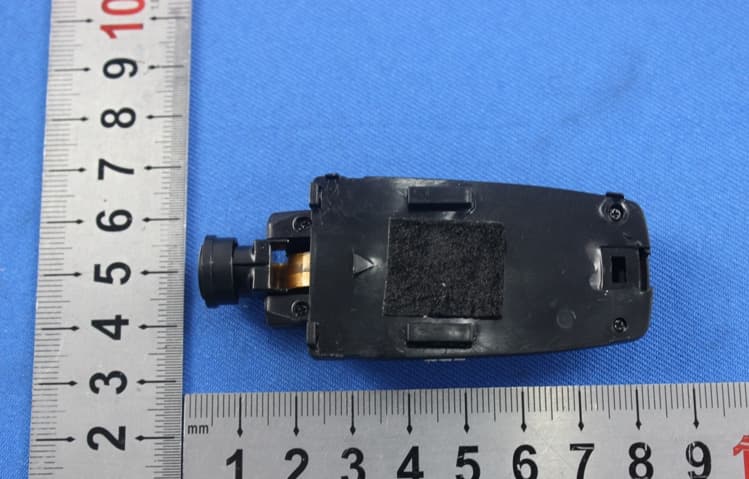
IYFZ1000
Oct 08, 2015wifi module (only for the camera)
Equipment Class
DTS - Digital Transmission System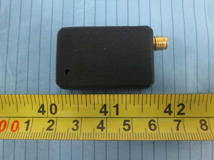
IYFFPVT1
Sep 28, 2015Tactic FPV-T1 5.8GHz 25mW Transmitter
Equipment Class
DXX - Part 15 Low Power Communication Device Transmitter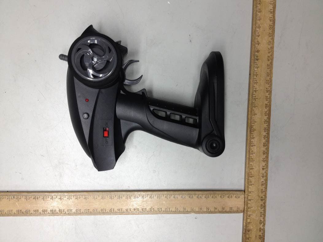
IYFRVLC01
Sep 08, 2015Radio Control Toy Transmitter (2.4GHz)
Equipment Class
DXX - Part 15 Low Power Communication Device Transmitter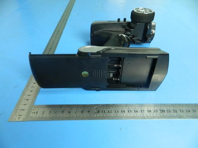
IYFDIDJ1001
Aug 28, 2015D103
Equipment Class
DSS - Part 15 Spread Spectrum Transmitter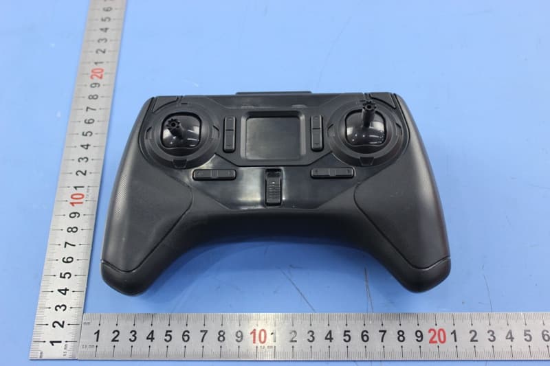
IYFMR100
Jul 01, 2015Radio controlled model quadcopter and transmitter/receiver
Equipment Class
DXX - Part 15 Low Power Communication Device Transmitter