IYFFS0803USB TX Interface
Hobbico Inc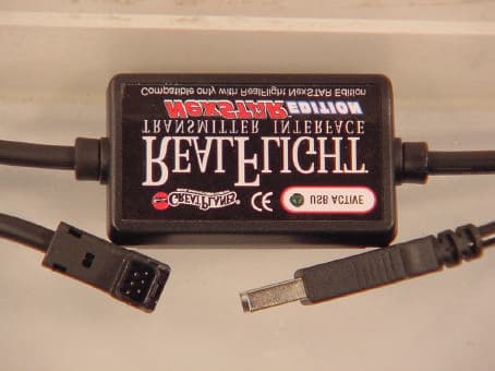
Click to zoom
Application Details
- Equipment Class
- JBP - Part 15 Class B Computing Device Peripheral
- Date of Grant
- Oct 16, 2003
- Application Purpose
- Original Equipment
- Date of Application
- Oct 16, 2003
- Equipment Note
- USB TX Interface
- Company
- Hobbico Inc
- Country
- United States
Documents & Files
Document Text
Text extracted from the exhibit documents filed with the FCC. Open a document above to read the original.
Users Manual
The NexSTAR USB Transmitter Interface ’ - - - - A A D D D D I I N N G G T T O O T T H H E E R R E E A A L L I I S S M M By definition, the R/C transmitter is a key component in all types of R/C flying. This unique method of control is part of what separates R/C from every other type of aviation. Consequently, a realistic transmitter is important to an authentic simulation of the R/C experience. With this in mind, we at Great Planes are proud to offer our NexSTAR USB Transmitter Interface. The NexSTAR USB Transmitter Interface Features of the NexSTAR USB Transmitter Interface: • USB compatibility and convenience. The ultimate convenience of “plug and play”, “hot pluggable” installation and removal, as well as the high-speed digital performance made possible by Universal Serial Bus (USB) technology. • Use your Actual R/C transmitter. The Transmitter Interface allows you to use your NexSTAR transmitter to control the action. This is a great way to familiarize yourself with the controller before heading to the flying field. • Easy setup and use. Pre-calibrated so you don’t even have to calibrate your NexSTAR transmitter, unlike other computer joysticks. Simply plug it in and go! T T R R A A N N S S M M I I T T T T E E R R I I N N T T E E R R F F A A C C E E F F E E A A T T U U R R E E S S This awesome interface brings you: • Full USB compatibility. The Transmitter Interface plugs directly into your computer’s USB port with little, if any, additional setup required. • High-speed data transfer ensures rapid, digitally precise response to your control input. • Hot pluggable—connect/disconnect your Transmitter Interface adapter without shutting down or rebooting the PC. • Total control with your actual R/C transmitter. You’ll get the ‘feel’ for controlling the NexSTAR with the same unit you’ll be using at the field. CONNECT THE USB TRANSMITTER INTERFACE Finally, plug the RealFlight NexSTAR Edition Transmitter Interface into a USB port on your computer (see diagram). On most computers, the USB ports are clearly labeled. Please note, the Transmitter Interface is hot pluggable or hot swappable. In other words, you can normally plug/unplug the Transmitter Interface without turning your computer off or rebooting. While your Transmitter Interface is plugged in, and your computer is turned “on”, a small green light on the Transmitter Interface should illuminate. This light, labeled “USB Active”, indicates that the Transmitter Interface is connected and working. Grasp the remaining Transmitter Interface cord (the one with the square connector) and firmly plug this into the trainer jack (a.k.a. buddy box) port located in the back of the NexSTAR transmitter. Turn the transmitter’s power “on.”
Cover Letter(s)
1 Mike Kuo From: Mike Kuo Sent: October102003Friday 4:56 PM To: '[email protected]' Cc: '[email protected]' Subject: Hobbico FCC ID: IYFFS0803, TCB assessment no:AN03T3306 Question #1: EUT is a PC peripheral device with USB interface. Per ANSI C63.4 section 11.2, the minimum test configuration shall include with external peripheral for each of two different types of available I/O protocols, Personal Computer ( notebook ), keyboard, video display unit . Based upon the test setup photos and peripheral used during the tests, the test configuration does not comply with ANSI C63.4 section 11.2 requirements. Please refer to ANSI C63.4 section 11.2 and redo radiated and AC line conducted tests. Submit revised test report with test setup photo and additional peripherals information. Question #2: When you test PC or PC peripheral devices, please give special attention on the device placement, per ANSI C63.4 fig 9 (a), the peripherals shall be separated by 10 cm . Best Regards Mike Kuo Compliance Certification Services 561F Monterey Road Morgan Hill CA 95037 Tel: (408)463-0885 x: 105 Fax: (408)463-0888 http://www.ccsemc.com
External Photos
Report No. : F690501/LF-EMC000173 External Phontos l Front View l Rear View
ID Label/Location Info
Report No. : F690501/LF-EMC000173 Lable Location and Label l Label Location l Label
Internal Photos
Report No. : F690501/LF-EMC000173 Internal Photos l Front View Main Board l Rear View Main Board
Test Report
Report No. : F690501/LF-EMC000173 Page : 1 of 11 FCC COMPLIANCE REPORT Reference No. : SKI-03-0223 Report No. : F690501/LF-EMC000173 Applicant : Hobbico Inc. Address of Applicant : 2904 Research Road, P.O. Box 9021, Champaign, Illinois 61826-9021, USA Equipment Under Test (EUT) : Name : NEXSTAR .46 SELECT ARF Model No. : USB TX INTERFACE Standards : FCC Part 15, Subpart B, Class B ANSI C63.4:1992 Date of Receipt : 25 August 2003 Date of Test : 10 October 2003 to 11 October 2003 Date of Issue : 13 October 2003 Test Result : PASS In the configuration tested, the EUT complied with the standards specified above. Remarks : This report details the results of the testing carried out on one sample, the results contained in this test report do not relate to other samples of the same product. The manufacturer should ensure that all products in series production are in conformity with the product sample detailed in this report. This report shall not be reproduced except in full, without the written approval of the laboratory. If the product in this report is used in any configuration other than that detailed in the report, the manufacturer must ensure the new system complies with all relevant standards. Kew-Seung, Lim EMC DIV. Manager SGS KES CO., LTD. EMC Laboratory Report No. : F690501/LF-EMC000173 Page : 2 of 11 Contents 1. General Information 1.1 Manufacturer Information 4 1.2 General Description of EUT 4 1.3 Details of EUT 4 1.4 Description of Support Units 4 1.5 Cable List 5 1.6 System Configuration 5 1.7 Test Set-Up Configuration 5 1.8 Measurement Procedure 6 1.9 Standards Applicable for Testing 6 1.10 Summary of Results 6 1.10 Alternative Type(s) / Model(s) 7 2. Radio Disturbance 2.1 Test Results 8 2.2 Frequency Range 8 2.3 Limit Of Conducted And Radiated Emission 8 2.3.1 Limit Of Conducted Emission Of FCC Part 15, Subpart B 8 2.3.2 Limit Of Radiated Emission Of FCC Part 15, Subpart B 8 2.4 Test of Conducted Emission 9 2.4.1 Test Instruments 9 2.4.2 Test Site 9 2.4.3 Operating Environment 9 2.4.4 Measurement Data 9 2.5 Test of Radiated Emission 10 2.5.1 Test Instruments 10 2.5.2 Test Site 10 2.5.3 Operating Environment 10 2.5.4 Measurement Data 10 3.Photographs of Test 11 Report No. : F690501/LF-EMC000173 Page : 3 of 11 1. General Information 1.1 Manufacturer Information Manufacturer : Hobbico Inc. Address : 2904 Research Road, P.O. Box 9021, Champaign, Illinois 61826-9021, USA 1.2 General Description of EUT Name : USB TX INTERFACE Model No. : NEXSTAR .46 SELECT ARF Serial No : N/A 1.3 Details of EUT Tested Power Supply : AC 110V, 60Hz Port : USB, Interface Description of Operating : Input signal from Radio Control System and Convert it into USB signal. Modifications to the EUT : None 1.4 Description of Support Units Product Model No. Serial No. Manufacturer Printer BJC-2100SP CME010503119 CANON PS/2 Mouse M-S34 LZB00207183 LOGITECH Keyboard SEM-DT35 05068271 SAMSUNG PC Dreamsys EX/TLB N/A TriGem Computer LCD Monitor TGL170PX FFSJ330232176 TriGem Computer Radio Control System SYSTEM 3000 N/A TOWER HOBBIES Report No. : F690501/LF-EMC000173 Page : 4 of 11 1.5 Cable List Start END Cable Spec. Name I/O Port Name I/O Port Length Shield EUT - PC USB 1.5 Shielded - Radio Control System I/O 1.5 Unshielded PC RGB LCD Monitor - 1.8 Shielded Parallel Printer - 1.8 Shielded PS/2 Mouse PS/2 Mouse - 1.8 Shielded Keyboard Keyboard - 1.7 Shielded USB EUT - 1.5 Shielded 1.6 System Configuration Description Model Serial No. Manufacturer Main Board SJ-S199 N/A N/A 1.7 Test Set-Up Configuration PC Radio Control System A Note PC Printer EUT PS/2 Mouse Keyboard Report No. : F690501/LF-EMC000173 Page : 5 of 11 1.8 Measurment Procedure Conducted Emission Testing was performed according ANSI C63.4:1992 in a shielded room with peripherals placed on a table, 0.8m high over a metal floor. It was located more than required distance away from the shielded room wall. Radiated Emission Testing was performed according to ANSI C63.4:1992 at the open field test site. The EUT was placed in a 0.8m high table along with the peripherals. The turn table was separated from the antenna distance 10meters. Cables were placed in a position to produce maximum emissions as determined by experimentation, and operation mode was selected for maximum. The frequencies and amplitudes of maximum emission were measured at varying azimuths, antenna heights and antenna polarities. Reported are maximized emission levels. 1.9 Standards Applicable for Testing Table of tests to be carried out under FCC Part 15, Subpart B, CLASS B Test Standards Status FCC Part 15,Subpart B, Class B Applicable Deviation from Standard No Deviation 1.10 Summary of Results The data collected shows that Model NEXSTAR .46 SELECT ARF complies with Part 15.109 and 107 of FCC Technical Rules. The highest emission level observed was at 0.27MHz for Q/P mode conducted emission with a margin of 18.5dB and at 0.27MHz for AV mode conducted emission with a margin of 18.0dB and at 528.04MHz radiated emission with a margin of 4.83dB. Report No. : F690501/LF-EMC000173 Page : 6 of 11 1.11 Alternative Type(s) / Model(s) Model NEXSTAR .46 SELECT ARF was chosen to test. The models to be certified are identical to the certified model, NEXSTAR .46 SELECT ARF except for model name. Part Number Model Name Basic Model HCAA17** NEXSTAR .46 SELECT ARF Added Models HCAA1736 HCAA1738 HCAA1740 HCAA1742 HCAA1744 HCAA1746 HCAA1748 HCAA1750 GPMZ4510 NEXSTAR .46 SELECT ARF 72.510MHz NEXSTAR .46 SELECT ARF 72.550MHz NEXSTAR .46 SELECT ARF 72.590MHz NEXSTAR .46 SELECT ARF 72.630MHz NEXSTAR .46 SELECT ARF 72.670MHz NEXSTAR .46 SELECT ARF 72.710MHz NEXSTAR .46 SELECT ARF 72.750MHz NEXSTAR .46 SELECT ARF 72.790MHz USB TRANSMITTER INTERFACE Report No. : F690501/LF-EMC000173 Page : 7 of 11 Radio Disturbance 2.1 Test Results Results Conducted Emission PASS Radiated Emission PASS 2.2 Frequency Range Conducted Emission : 150 kHz - 30 MHz Radiated Emission : 30 MHz - 1000 MHz, Above 1000MHz 2.3 Limits Of Conducted…
Text truncated - open the document above for the full version.
Test Setup Photos
Report No. : F690501/LF-EMC000173 Page : 10 of 11 3. Photographs of Test l Front View of Conducted Emission l Rear View of Conducted Emission Report No. : F690501/LF-EMC000173 Page : 11 of 11 l Front View of Radiated Emission l Rear View of Radiated Emission
Contact Information
Applicant
Neal Cloud(Senior Product Manager)
Test Firm
SGS Korea Co., Ltd.Julia Choi
Technical Specifications
| # | Rule Parts | Frequency Range | Power Output |
|---|---|---|---|
| 1 | 15B | - | - |
Other Applications from Hobbico Inc
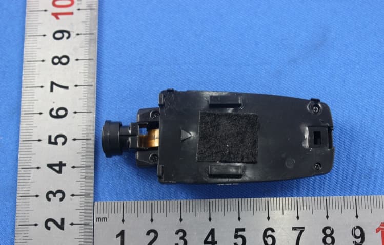
IYFZ1000
Oct 08, 2015wifi module (only for the camera)
Equipment Class
DTS - Digital Transmission System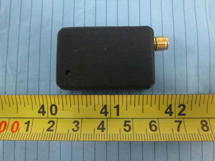
IYFFPVT1
Sep 28, 2015Tactic FPV-T1 5.8GHz 25mW Transmitter
Equipment Class
DXX - Part 15 Low Power Communication Device Transmitter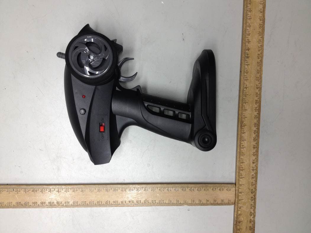
IYFRVLC01
Sep 08, 2015Radio Control Toy Transmitter (2.4GHz)
Equipment Class
DXX - Part 15 Low Power Communication Device Transmitter
IYFDIDJ1001
Aug 28, 2015D103
Equipment Class
DSS - Part 15 Spread Spectrum Transmitter
IYFMR100
Jul 01, 2015Radio controlled model quadcopter and transmitter/receiver
Equipment Class
DXX - Part 15 Low Power Communication Device Transmitter