IYFR5FM-72Communications Receiver
Hobbico Inc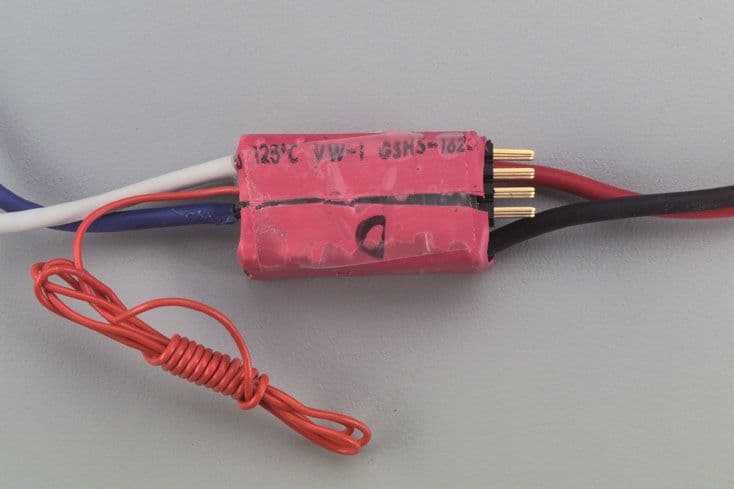
Click to zoom
Application Details
- Equipment Class
- CXX - Communications Rcvr for use w/ licensed Tx and CBs
- Date of Grant
- Aug 22, 2001
- Application Purpose
- Original Equipment
- Date of Application
- Aug 22, 2001
- Equipment Note
- Communications Receiver
- Frequency Range
- 72.01000000 - 72.99000000
- Company
- Hobbico Inc
- Country
- United States
Documents & Files
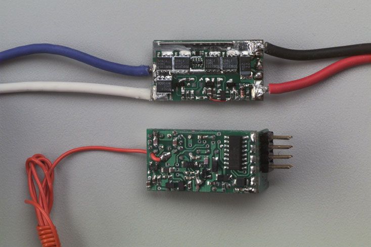
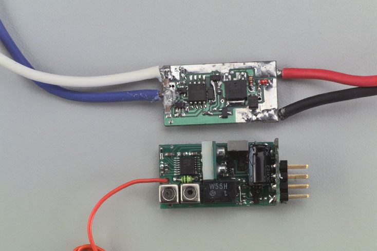
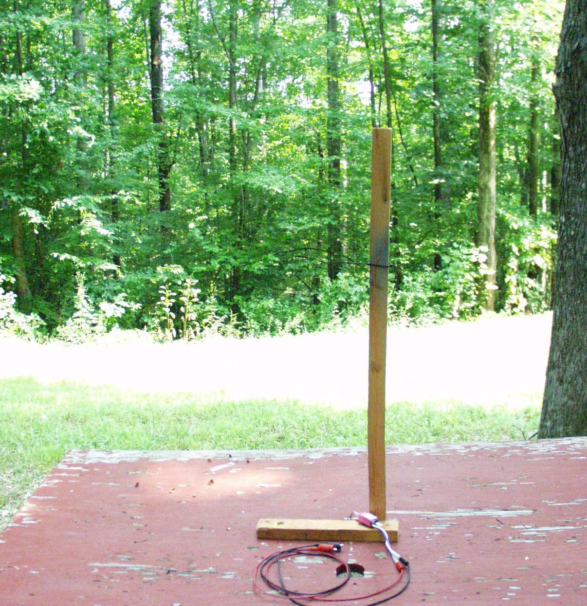
Document Text
Text extracted from the exhibit documents filed with the FCC. Open a document above to read the original.
Users Manual
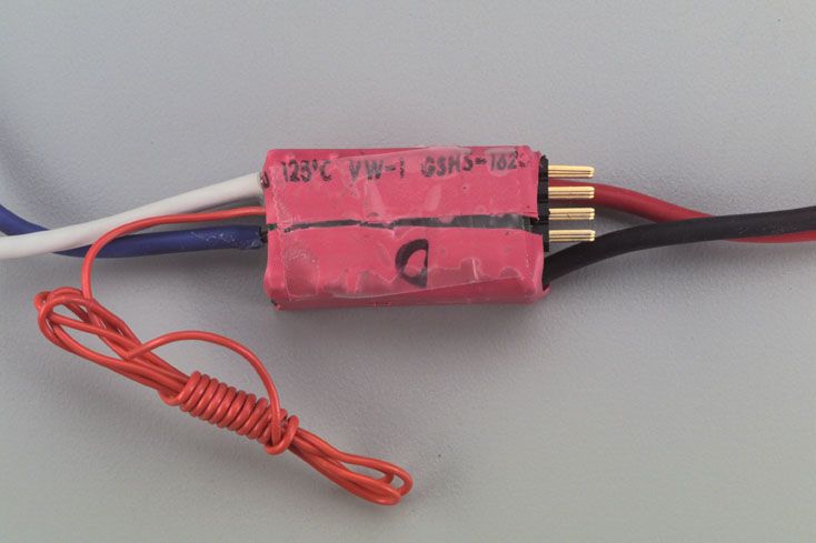
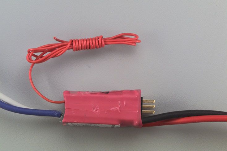
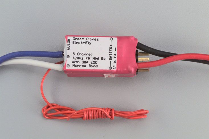
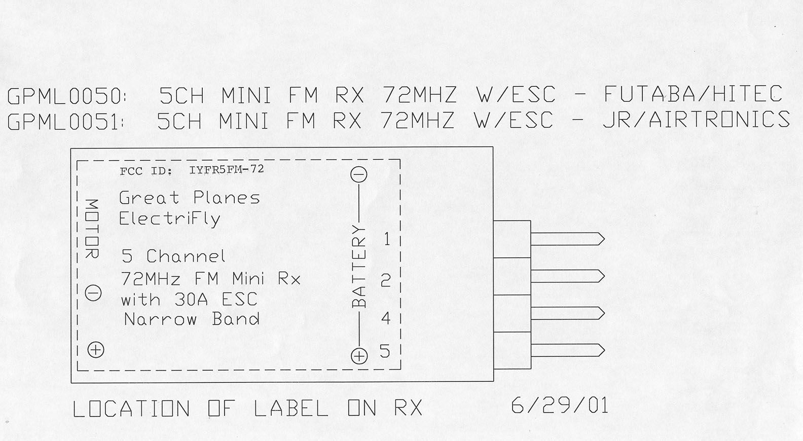
(Great Planes® logo) GREAT PLANES (ElectriFly™ logo) ELECTRIFLY 5-CHANNEL MINI FM RECEIVER 72MHZ - WITH 30A ELECTRONIC SPEED CONTROL INSTRUCTION MANUAL FOR R/C AIRCRAFT USE Congratulations on your purchase of the ElectriFly™ 5-Channel Mini FM Receiver w ith ESC! This single- conversion receiver with built-in electronic speed control is a perfect choice for use in park flyer and smaller electric R/C airplanes and gliders. As an FM (frequency modulated) narrow-band system, it's far less vulnerable to interference than AM receivers. While few receivers of the same physical size and weight can match it’s in-flight range, the ElectriFly 5-Channel FM Rx exhibits excellent interference rejection characteristics for clean, trouble-free flights. With an operating range that is great for smaller aircraft, this receiver is not as well suited for large aircraft. An extra step has been taken to help reduce the size and weight of equipment on-board the aircraft, by incorporating a 30A (max.) electronic speed contol into the receiver itself. With features that include “Safe Start” to prevent accidental motor starts, BEC circuitry, low voltage cut-off for maintaining radio control, thermal shutdown and more, the ESC circuitry is more than just a novelty, it is a convenient, intelligent, and powerful addition to the receiver. Please read this entire manual carefully and use your radio system safely. Pay special attention to all precautions and warnings to ensure the safest operation. WARNINGS *Do not fly simultaneously on a frequency that is already being used in your area. Doing so could cause unwanted interference and cause a crash, and possibly bodily harm. *Do not fly in the rain or at night. Water can permanently damage many of the components in the radio system, possibly causing loss of control and a crash. *Only fly at liscensed R/C flying fields. Fly at safe distances away from other people, objects in the air, buildings, electrical lines, or any other object which could possibly impede safe flying. Failure to do so could cause a crash and possibly bodily harm, and physical damage to other property. *Extend the Rx antenna to maximum length w hen flying. Failure to do so could reduce the effective range of the radio system, possibly resulting in a crash. Always test the radio system before use. Failure to ensure proper radio operation before flight could result in a crash. *Do not store the radio system in extreme heat (exceeding 104 o F) or cold (below -14 o F), in direct sunlight, in high humidity, in high vibration environments, or in dusty areas. *Never use more than 10 cells (12 volts) for the main battery pack. *The ceramic capacitors must be properly installed on the motor to prevent radio interference. *Always disconnect the motor battery from the ESC when not in use. *Always switch on the transmitter before switching on the ESC. *Use heat shrink to insulate any bare wires from the motor battery to the ESC and from the ESC to the motor to prevent a short circuit. *Allow the ESC to cool before touching. MOUNTING THE RECEIVER / SPEED CONTROL Determine the best location for the Rx/ESC inside the fuselage. The location should be such that allows good airflow for proper cooling, and closely enough so that the motor w ires can reach the motor. It is highly recommended to put cooling air intake holes in the front of the fuselage and exit holes towards the aft end. The best method to mount the Rx/ESC in the fuselage is with Velcro®. This allows the ESC to be removed and repositioned easily. If the ESC will be mounted on wood, first saturate the wood with thin CA and allow to dry. This will provide a good surface for the Velcro to adhere to. Cut a piece of Velcro (both hook and loop) approximately 1/2" x 1". Remove the backing from the hook (hard) material and attach it to the inside of the fuselage. Clean the bottom of the ESC with rubbing alcohol and attach the loop (soft) material. INSTALL THE MOTOR CAPACITORS Motors generate radio noise which can interfere with your receiver and cause problems. Your ESC includes two 100μF (104) and one 47μF (473) non-polarized, ceramic capacitors. These capacitors must be used at all times, and on every motor to help reduce the radio noise generated by the motor and prevent possible damage to the ESC. A. Cut a piece of heat shrink tubing long enough to cover one of the leads on both of the 100μF capacitors, leaving approximately 1/4" of the lead exposed at the bottom. B. Solder one exposed capacitor lead to the positive (+) brush terminal on the motor. C. Solder one exposed lead on the second capacitor to the negative (-) brush terminal on the motor. D. Solder the remaining leads from both capacitors to the metal side of the motor case. E. Cut two pieces of heat shrink tubing long enough to cover both leads on the 47μF capacitor, leaving approximately 1/4" of the lead exposed at the bottom. F. Solder one lead to the positive brush terminal, and the other lead to the negative brush terminal. G. Connect the positive (red) lead from the ESC to the positive brush terminal on the motor and the negative (black) lead to the negative brush terminal. SCHOTTKY DIODE Installing the schottky diode will provide a slight increase in the ESC efficiency and reduce its operating temperature. To avoid damage to the diode, it must be installed correctly, as follows: A. Solder the lead closest to the silver band on the diode body to the positive (+) terminal on the motor. B. Solder the lead opposite the silver band to the negative (-) terminal on the motor. TRANSMITTER ADJUSTMENTS Adjusting the transmitter is critical for proper ESC operation. The transmitter throttle adjustments should be set as follows: 1. Set the transmitter’s throttle travel adjustment, ATV, EPA or ATL to maximum. 2. Set the throttle trim and sub-trim to neutral or zero. 3. Set the throttle reversing switch to reverse. RECEIVER OPERATION (Show pic of receiver, call out channels, antenna, etc.) A. Connect servo…
Text truncated - open the document above for the full version.
Test Report
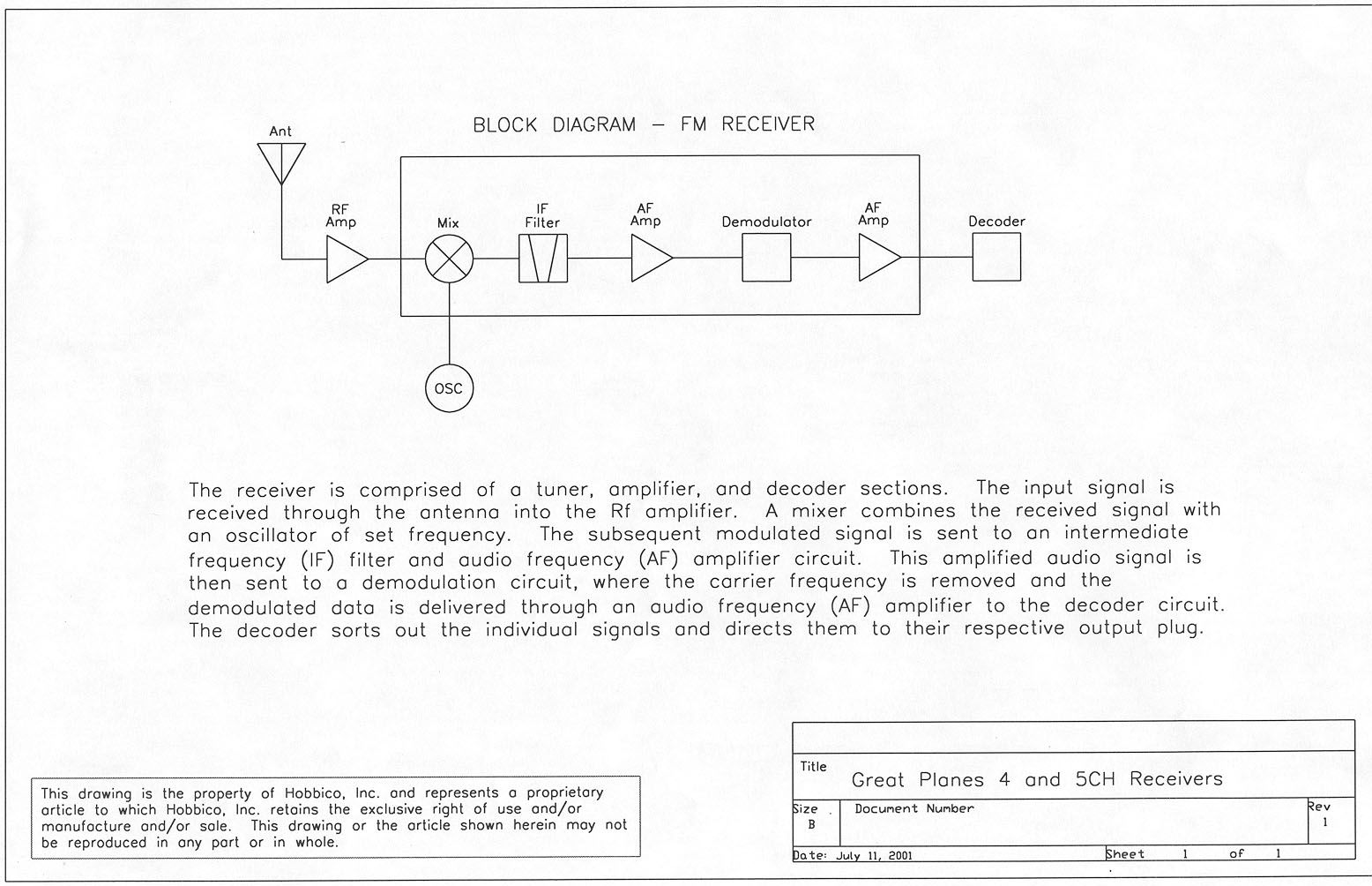
ENGINEERING STATEMENT In Regard to Measurements on HOBBICO – Hobby Corporation of America MODEL: GPML0050 FCC ID: IYFR5FM-72 A. INTRODUCTION Hyak Laboratories, Inc. has been authorized by Hobbico to determine compliance with FCC rules, Part 15, Subpart B. The device operates in the 72 MHz band and is intended for use as a model aircraft R/C receiver. B. DESCRIPTION OF DEVICE The device incorporates a super-heterodyne design. The following information is supplied as requested in FCC Bulletin OCE 24: 1. Service in which the device will be used: Part 15. (95) 2. Function of device: R/C Receiver 3. Tuning range: 72.01 – 72.99 MHz. 4. IF used: 455 kHz. 5. Fundamental frequency of principal oscillators in the device. First local oscillator: (F o +0.455) MHz. C. DESCRIPTION OF MEASUREMENT FACILITIES A description of the Hyak Laboratories' radiation test facility is a matter of record with the FCC. The facility was accepted for radiation measurements from 30 to 1000 MHz on October 1, 1976, and is currently listed as an accepted site. D. DESCRIPTION OF MEASUREMENT PROCEDURE: RADIATED EMISSIONS Measurements of radiated field strength were made using ANSI C63.4 (1992) as the basic procedure. Measurements were made with 3-meter spacing between the device under test and the test equipment antenna. The antenna(s) connected to the device under test consisted of the integral 60 cm antenna supplied with the receiver. The device under test was placed on a rotatable table 80 cm in height. Measurement of field strength was made through use of Tektronix 494P spectrum analyzer in conjunction with Singer DM- 105A series or EMCO 3221 calibrated dipoles or EMCO 3115 DRG horn. For each spurious emission identified between 30 to 2000 MHz (per Para 15.33(b)(1)), the test sample was rotated for maximum pickup, the test antenna varied in elevation, and the test antenna polarization shifted between horizontal to vertical in order to maximize observed signals. E. REPORT OF RADIATED EMISSIONS 1. Table 1 lists the frequency and amplitude of all signals observed from 30 to 2000 MHz. All other emissions were more than 20 dB below the limits of paragraph 15.109 of the FCC Rules. 2 TABLE 1 RADIATED SPURIOUS EMISSIONS Measured at 3 meters PART 15(B) PARA. 15.109 Frequency Frequency To Which of Meter Antenna Field 1 Tuned Emission Reading Factor Intensity FCC Limit dB to (MHz) (MHz) (dBm) (dB) uV/m @ 3m uV/m @ 3m Limit 72.270 72.725 -87.0 8.2 26 100 -12 72.270 145.450 -101.0 16.9 14* 150 -21 72.270 218.175 -105.0 11.6 5* 200 -32 72.710 73.166 -82.2 8.4 46 100 - 6.8 72.710 146.332 -97.8 16.9 20 150 -17 72.710 219.494 -101.0 11.4 7* 200 -29 Note 1: uV/m = Log -1dBu/m 20 dBu = dBm + antenna factor + 107 *Reference data, 20 dB or more below FCC limit. RADIATED SPURIOUS EMISSIONS FCC ID: IYFR5FM-72 TABLE 1 3 F. PROCEDURE - AC LINE CONDUCTED SPURIOUS The GPML0050 receiver operates from model toy control power; there is no connection to ac power lines. G. STATEMENT Technical test data are from tests performed by me or under my supervision. My qualifications are a matter of record with the Federal Communications Commission. I personally attest to the accuracy of the test data submitted as a part of this engineering statement. __________________________________ Rowland S. Johnson Dated: August 6, 2001 4
Contact Information
Applicant
Neal Cloud(Senior Product Manager)
Test Firm
Hyak Laboratories, Inc.Rowland Johnson
703-451-1188
Technical Specifications
| # | Rule Parts | Frequency Range | Power Output |
|---|---|---|---|
| 1 | 15B | 72.01 MHz - 72.99 MHz | - |
Other Applications from Hobbico Inc
IYFZ1000
Oct 08, 2015wifi module (only for the camera)
Equipment Class
DTS - Digital Transmission System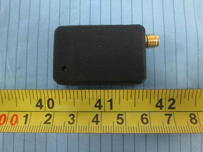
IYFFPVT1
Sep 28, 2015Tactic FPV-T1 5.8GHz 25mW Transmitter
Equipment Class
DXX - Part 15 Low Power Communication Device Transmitter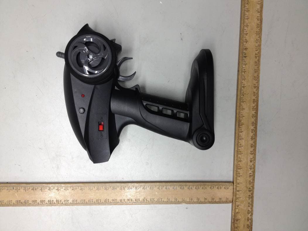
IYFRVLC01
Sep 08, 2015Radio Control Toy Transmitter (2.4GHz)
Equipment Class
DXX - Part 15 Low Power Communication Device Transmitter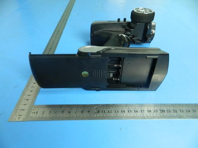
IYFDIDJ1001
Aug 28, 2015D103
Equipment Class
DSS - Part 15 Spread Spectrum Transmitter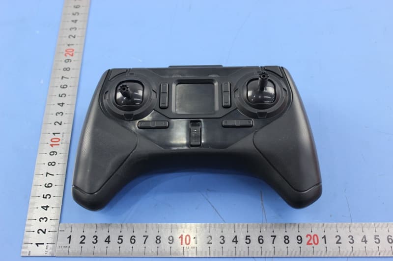
IYFMR100
Jul 01, 2015Radio controlled model quadcopter and transmitter/receiver
Equipment Class
DXX - Part 15 Low Power Communication Device Transmitter