IYFTTX240A2.4 GHz Radio Control System
Hobbico Inc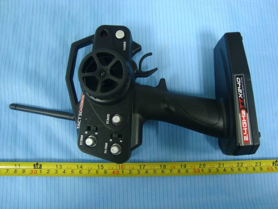
Click to zoom
Application Details
- Equipment Class
- DSS - Part 15 Spread Spectrum Transmitter
- Date of Grant
- Jan 20, 2011
- Application Purpose
- Original Equipment
- Date of Application
- Jan 20, 2011
- Equipment Note
- 2.4 GHz Radio Control System
- Frequency Range
- 2403.00000000 - 2480.00000000
- Company
- Hobbico Inc
- Country
- United States
Documents & Files
Document Text
Text extracted from the exhibit documents filed with the FCC. Open a document above to read the original.
Users Manual
Thank you for making the Tactic TTX240 2.4GHz system your choice for radio control! This system uses modern 2.4GHz Spread Spectrum technology – an innovation that allows for automatic channel selection and interference- free control of R/C models. It is strongly recommended to completely read this manual before use! Damage resulting from misuse or modifi cation will void your warranty. FEATURES ● 2.4GHz Spread Spectrum Technology ● Transmitter can bind to multiple receivers ● Tiny, lightweight receiver with internal antenna ● Built-in fail-safe ● Steering and throttle trim dials ● Steering and throttle servo reversing ● Steering rate adjustment ● Power LED with low battery warning indication INSTRUCTION MANUAL 2.4GHz Radio Control System ™ TACJ0245 v2.2 2 TRANSMITTER The transmitter (Tx) requires 4 “AA” batteries. Non-rechargeable alkaline or rechargeable nickel-cadmium (NiCd) or nickel-metal hydride (NiMH) cells can be used. Do not mix old and new cells, or mix non-rechargeable alkaline cells with rechargeable NiCd or NiMH cells, etc. See the SERVOS AND ACCESSORIES section at the end of this manual for optional rechargeable NiCd and NiMH batteries and chargers. Note the TTX240 transmitter does not include a charge jack for rechargeable cells. A separate “AA” cell charger will be necessary. To install the batteries, slide open the battery door on the bottom of the Tx (see fi gure 1). Install the batteries in the holder as shown in the diagram (see marks molded inside the case). Make sure to note the proper polarities on each cell. Close the battery door. IMPORTANT: Do not operate an R/C model with weak batteries as it could result in reduced range and/or possible loss of control! Press the power switch to turn the Tx on (see fi gure 2). The “POWER” LED should illuminate. If not, turn off the Tx and check the batteries to make sure each cell is fi rmly in place and in the proper direction. If the Tx LED blinks, the batteries are low on power and should be replaced. When operating the model, carefully rotate the Tx antenna so that it’s always locked in the full upright position. + - + - + - + - 4 “AA” Cells Figure 1 Antenna Power LED On/Off Power Switch Battery Cover Steering Rate Throttle Reversing Steering Trim Steering Reversing Throttle Trim Figure 2 3 BIND THE RECEIVER TO THE TRANSMITTER For proper installation and operation of the 2.4GHz transmitter and receiver system, it is necessary to “bind” them together electronically. This ensures sole communication between the two and prevents other transmitters from being able to control the receiver. To bind the Tx and Rx: 1. Turn on the transmitter. 2. Apply power to the receiver (see the INSTALLATION section that follows for how to do this). 3. If the receiver’s LED fl ashes once and then stays on, the Rx is already bound to the Tx and you can skip to the next section. Otherwise, push and hold the receiver’s “BIND” button until its LED glows red and then turns off after about one second. 4. Release the bind button. 5. If the binding is successful, the LED will fl ash once and then remain ON. 6. Test for proper Tx / Rx functionality by completing the next section. If it doesn’t seem the radio has bound properly, repeat steps 1-6 above. INSTALLATION Receiver: Mount the receiver as specifi ed in your model’s instructions. As a guideline, mount in a secure location using double-sided tape. Route the servo wires so they do not interfere with any moving parts. For boat applications, it’s highly recommended to wrap the receiver in a balloon or enclose it in a water-tight box. Servos: See the SERVOS AND ACCESSORIES section at the end of this manual for a full list of optional servos. CENTER THE TRIM DIALS on the Tx. Mount the servos inside the model and connect the linkages to the servo using an appropriate length servo arm. Make sure all mechanical linkages are free of obstructions and can move smoothly. Connect the servos to the receiver as shown in Figure 3. Turn the transmitter’s trim dials to fi nely adjust the servo’s center point as needed to match the installation. Electronic Speed Control (ESC): If using an electronic speed control, connect it to channel 2 of the receiver (throttle). Center the transmitter’s throttle trim and follow the ESC instructions for programming. Figure 3 (2) Throttle Servo (1) Steering Servo (B) Battery / Switch 4 Switch / Battery: It may not be necessary to use the included switch harness and 4-cell battery holder if using an optional electronic speed control (ESC). Check the instructions with your ESC for further information. Otherwise, mount the included switch harness into the model as instructed in the model’s manual, and insert the switch harness’s proper mating plug into the receiver’s “BAT” slot (bottom). For off-road environments, it’s a good idea to wrap or enclose the switch harness to prevent dirt from entering the switch and causing poor operation. Insert four “AA” alkaline, NiCd, or NiMH batteries in the included 4-cell battery holder (note proper polarity). Connect the battery holder to the switch harness and the switch harness to the BAT slot. SYSTEM CHECK Turn on the Tx, then the Rx. Make sure all servos operate according to the movement of the Tx controls (refer to fi gure 4). Steering: Turn the steering wheel left and right. Make sure there are no obstructions with the steering servo’s movements, and the servo moves in the proper direction. If the steering wheel is turned to the right but the model turns left, reverse the position of the Steering Reversing switch. Steering rate: This dial adjusts the limits that the steering servo can travel on each side. Turning the dial will widen or narrow the steering end points. Adjusting this dial to your preference can help to customize control of steering in different applications. Throttle: Squeeze the throttle trigger to make the car move forward. If the car moves backwards, reverse the position of the Throttle Reversing switch. (See the model’s instr…
Text truncated - open the document above for the full version.
External Photos
EXHIBIT B - EUT EXTERNAL PHOTOGRAPHS EUT – Front View EUT – Rear View EUT – Bottom View EUT – Side View
ID Label/Location Info
EXHIBIT A - FCC ID LABELING AND LOCATION FCC ID Label & Warning Statement FCC ID Label Location The label shown shall be permanently affixed at a conspicuous location on the device and be readily visible to the user at the time purchase (Labeling requirements per 2.925) Label here Warning here
Internal Photos
EXHIBIT C - EUT INTERNAL PHOTOGRAPHS EUT – Cover Off View Antenna EUT – Main Board shielded Top View EUT – Main Board shielded off Top View EUT –Main Board Bottom View
RF Exposure Info
Hobbico, Inc. FCC ID: IYFTTX240A Report No.: RSZ10102503 Page 9 of 34 FCC Part15.247 Test Report FCC §15.247 (i) & §1.1307 (b) (1) & §2.1091- MAXIMUM PERMISSIBLE EXPOSURE (MPE) Standard Applicable According to subpart 15.247 (i) and subpart 1.1307 (b)(1), 2.1091 systems operating under the provisions of this section shall be operated in a manner that ensures the public is not exposed to RF energy level in excess of the communication guidelines. Limits for General Population/Uncontrolled Exposure Limits for General Population/Uncontrolled Exposure Frequency Range (MHz) Electric Field Strength (V/m) Magnetic Field Strength (A/m) Power Density (mw/cm 2 ) Averaging Time (Minutes) 0.3-1.34 614 1.63 *(100) 30 1.34-30 824/f 2.19/f *(180/f 2 ) 30 30-300 27.5 0.073 0.2 30 300-1500 / / f/1500 30 1500-100,000 / / 1.0 30 f = frequency in MHz * = Plane-wave equivalent power density Test Data Predication of MPE limit at a given distance S = PG/4πR² Where: S = power density (in appropriate units, e.g. mW/cm 2 ) P = power input to the antenna (in appropriate units, e.g., mW). G = power gain of the antenna in the direction of interest relative to an isotropic radiator, the power gain factor, is normally numeric gain. R = distance to the center of radiation of the antenna (appropriate units, e.g., cm) Maximum peak output power at antenna input terminal: 20.26 (dBm) Maximum peak output power at antenna input terminal: 106.17(mW) Prediction distance: >20 (cm) Predication frequency: 2403 (MHz) Antenna Gain (typical): 2 (dBi) Maximum Antenna Gain: 1.58 (numeric) The worst case is power density at predication frequency at 20 cm: 0.033 (mW/cm 2 ) MPE limit for general population exposure at prediction frequency: 1.0 (mW/cm 2 ) Result The predicted power density level at 20 cm is 0.033 mw/cm 2 which is below the uncontrolled exposure limit of 1.0 mw/cm 2 , The EUT is used at least 20 cm away from user’s body. It is determined as mobile equipment and complies with the MPE limit.
Test Report
Note: This test report is prepared for the customer shown above and for the device described herein. It may not be duplicated or used in part without prior written consent from Bay Area Compliance Laboratories Corp. This report must not be used by the customer to claim product certification, approval, or endorsement by NVLAP*, NIST, or any agency of the Federal Government. * This report may contain data that are not covered by the NVLAP accreditation and are marked with an asterisk “*” (Rev.2) FCC PART 15.247 MEASUREMENT AND TEST REPORT For Hobbico, Inc. 2904 Research Road, Champaign, Illinois 61826, USA FCC ID: IYFTTX240A Report Type: Original Report Product Type: 2.4 GHz FHSS TRANSMITTER Test Engineer: Alvin Huang Report Number: RSZ10102503 Report Date: 2010-12-14 Reviewed By: Merry Zhao EMC Engineer Prepared By: Bay Area Compliance Laboratories Corp. (Shenzhen) 6/F, the 3rd Phase of WanLi Industrial Building, ShiHua Road, FuTian Free Trade Zone Shenzhen, Guangdong, China Tel: +86-755-33320018 Fax: +86-755-33320008 Hobbico, Inc. FCC ID: IYFTTX240A Report No.: RSZ10102503 Page 2 of 34 FCC Part15.247 Test Report TABLE OF CONTENTS GENERAL INFORMATION.......................................................................................................................................4 PRODUCT DESCRIPTION FOR EQUIPMENT UNDER TEST (EUT) .....................................................................................4 OBJECTIVE...................................................................................................................................................................4 RELATED SUBMITTAL(S)/GRANT(S).............................................................................................................................4 TEST METHODOLOGY..................................................................................................................................................4 TEST FACILITY.............................................................................................................................................................4 SYSTEM TEST CONFIGURATION ..........................................................................................................................6 DESCRIPTION OF TEST CONFIGURATION......................................................................................................................6 EUT EXERCISE SOFTWARE..........................................................................................................................................6 EQUIPMENT MODIFICATIONS.......................................................................................................................................6 LOCAL SUPPORT EQUIPMENT LIST AND DETAILS........................................................................................................6 EXTERNAL I/O CABLE..................................................................................................................................................6 CONFIGURATION OF TEST SETUP.................................................................................................................................6 BLOCK DIAGRAM OF TEST SETUP................................................................................................................................7 SUMMARY OF TEST RESULTS ...............................................................................................................................8 FCC §15.247 (i) & §1.1307 (b) (1) & §2.1091- MAXIMUM PERMISSIBLE EXPOSURE (MPE)..............................9 STANDARD APPLICABLE..............................................................................................................................................9 TEST DATA..................................................................................................................................................................9 FCC §15.203 - ANTENNA REQUIREMENT...........................................................................................................10 APPLICABLE STANDARD............................................................................................................................................10 ANTENNA CONNECTOR CONSTRUCTION....................................................................................................................10 FCC §15.209, §15.205 & §15.247(d) - SPURIOUS EMISSIONS.............................................................................11 APPLICABLE STANDARD............................................................................................................................................11 MEASUREMENT UNCERTAINTY..................................................................................................................................11 EUT SETUP................................................................................................................................................................11 EMI TEST RECEIVER & SPECTRUM ANALYZER SETUP..............................................................................................12 TEST EQUIPMENT LIST AND DETAILS.........................................................................................................................12 TEST PROCEDURE......................................................................................................................................................12 CORRECTED AMPLITUDE & MARGIN CALCULATION.................................................................................................12 TEST RESULTS SUMMARY..........................................................................................................................................13 TEST DATA................................................................................................................................................................13 FCC §15.247(a) (1) - CHANNEL…
Text truncated - open the document above for the full version.
Test Setup Photos
EXHIBIT D - TEST SETUP PHOTOGRAPHS Below 1 GHz: Radiated Emissions - Front View Below 1 GHz: Radiated Emissions - Rear View Above 1 GHz: Radiated Emissions - Front View Above 1 GHz: Radiated Emissions - Rear View
Contact Information
Applicant
Neal Cloud(Senior Product Manager)
Test Firm
Bay Area Compliance Laboratory Corp. (Shenzhen)John Chan
Technical Specifications
| # | Rule Parts | Frequency Range | Power Output |
|---|---|---|---|
| 1 | 15C | 2.40 GHz - 2.48 GHz | 106.00 mW |
Other Applications from Hobbico Inc
IYFZ1000
Oct 08, 2015wifi module (only for the camera)
Equipment Class
DTS - Digital Transmission System
IYFFPVT1
Sep 28, 2015Tactic FPV-T1 5.8GHz 25mW Transmitter
Equipment Class
DXX - Part 15 Low Power Communication Device Transmitter
IYFRVLC01
Sep 08, 2015Radio Control Toy Transmitter (2.4GHz)
Equipment Class
DXX - Part 15 Low Power Communication Device Transmitter
IYFDIDJ1001
Aug 28, 2015D103
Equipment Class
DSS - Part 15 Spread Spectrum Transmitter
IYFMR100
Jul 01, 2015Radio controlled model quadcopter and transmitter/receiver
Equipment Class
DXX - Part 15 Low Power Communication Device Transmitter