IYFTTX24GAANYLINK 2.4 GHz Radio Adapter
Hobbico Inc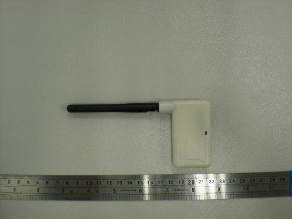
Click to zoom
Application Details
- Equipment Class
- DSS - Part 15 Spread Spectrum Transmitter
- Date of Grant
- Oct 30, 2011
- Application Purpose
- Original Equipment
- Date of Application
- Oct 30, 2011
- Equipment Note
- ANYLINK 2.4 GHz Radio Adapter
- Frequency Range
- 2403.00000000 - 2480.00000000
- Company
- Hobbico Inc
- Country
- United States
Documents & Files
Document Text
Text extracted from the exhibit documents filed with the FCC. Open a document above to read the original.
Users Manual
The AnyLink SLT 2.4GHz Radio Adapter allows nearly any R/C transmitter (Tx) to bind with Tactic’s ultra-small, lightweight, and inexpensive 2.4GHz receivers (Rx). Futaba ® and Hitec ® brand transmitters must have a trainer jack. JR ® and Spektrum ® transmitters must have a charge jack and trainer/D.S.C. jack. See page 15 for a Tx compatibility chart. Such transmitters can originally be designed for use on 72MHz, 2.4GHz, FM, PCM, etc. The acceptable flying range with AnyLink and a Tactic receiver is 1000 feet. Read this manual in its entirety before use! Damage resulting from misuse or modifi cation will void your warranty. ITEMS INCLUDED (1) AnyLink 2.4GHz Radio Adapter (1) Futaba Square Adapter Cable (1) JR/Spektrum Adapter Cable (2) Lengths of hard locking adhesive strips 1"(25.4mm) x 1.5" (38mm) INSTRUCTION MANUAL 2.4GHz Radio Adapter2.4GHz Radio Adapter ™ ™ TACJ2000 AnyLink Mnl.indd 1TACJ2000 AnyLink Mnl.indd 110/26/2011 1:04:26 PM10/26/2011 1:04:26 PM 2 MOUNTING ANYLINK Mount AnyLink high on the rear of the Tx, and extend its antenna to point upwards from the top of the Tx as much as possible. Rotate the antenna as shown above. Two strips of hard locking fasteners are included for attaching AnyLink to the rear of the host Tx. INPUT POWER AND TRANSMITTER CONNECTIONS Cables are included for attaching AnyLink to Futaba radios having a square trainer jack, and compatible JR/Spektrum radios. Other cables are available separately (see page 9). The cable with two connectors is for Futaba. The cable with three connectors is for JR and Spektrum. Using the appropriate cable, connect AnyLink to the Tx as explained below. Input Power Connection: AnyLink requires power to be taken from the host Tx through the appropriate cable. Insert the cable’s universal- style servo plug into AnyLink’s INPUT jack. Make sure the Tx battery is fully charged prior to operation. Replace weak alkaline batteries, or fully charge rechargeable batteries before attempting a flight. Futaba and Hitec Transmitters: Connect the cable’s trainer plug to the Tx trainer jack. This connection will provide both power and signal from the Tx to AnyLink. Input Jack Cable TACJ2000 AnyLink Mnl.indd 2TACJ2000 AnyLink Mnl.indd 210/26/2011 1:04:27 PM10/26/2011 1:04:27 PM 3 WARNING: Failure to insert the cable connector properly can damage the AnyLink and the transmitter! An optional cable is required to connect Hitec’s Aurora Tx to AnyLink (see page 9). Remove the antenna and module from the Aurora Tx.Once connected to AnyLink, attach the cable’s second connector to the three left-most module pins on the rear of the Tx, as shown. Make SURE the metal terminals on the cable face upwards when connecting to the Tx. Hitec Aurora Tx Tx module pins JR and Spektrum Transmitters: Connect the cable’s “Signal Plug” to the transmitter’s trainer/D.S.C. jack, as shown below. This should cause the Tx logic circuit to turn on automatically, which is normal, and create the signal connection from the Tx to AnyLink. Do NOT connect the remaining power plug to the Tx at this time. Signal plug (DSC) Power plug (Charge jack) JR/Spektrum Tx IMPORTANT! Make sure all connections between AnyLink and the host Tx are solid physically and cannot easily become dislodged at any time. Otherwise, power or signal loss could occur resulting in a loss of control of the aircraft. Never operate a model with weak Tx batteries as loss of control could result! TACJ2000 AnyLink Mnl.indd 3TACJ2000 AnyLink Mnl.indd 310/26/2011 1:04:27 PM10/26/2011 1:04:27 PM 4 ANYLINK OPERATION IMPORTANT! Remove the propeller from the airplane prior to operating AnyLink with the radio system. Failure to do so could result in personal injury if the motor unexpectedly turns during setup. 1. Remove the Rf module or crystal from the host Tx if possible. Leave the Tx’s own antenna in a retracted or folded position. AnyLink’s own antenna will transmit the signal to the Tactic Rx. 2. Make sure 72MHz computer radios are set to PPM mode. 3. Move the Tx throttle stick to the minimum position. 4. Futaba and Hitec transmitters: For computer radios which offer the option to transmit a signal when Tx power is turned ON, make sure “YES” is selected. Turning the Tx power switch ON will supply power to the Tx and AnyLink simultaneously. Listen for AnyLink to beep ONCE when power is applied to confirm it’s configured for Futaba/Hitec transmitters. Turn the Tx power switch ON and listen for tones from AnyLink. If AnyLink beeped twice, skip to the CHANNEL MAPPING section below. Otherwise, skip to step 6. 5. JR and Spektrum transmitters: With the cable’s “Signal Plug” connected to the Tx trainer/D.S.C. jack, connecting the cable’s “Power Plug” to the Tx charge jack will automatically turn on AnyLink. Listen for AnyLink to beep TWICE when power is applied to confirm it’s configured for JR/Spektrum transmitters. IMPORTANT! Do NOT turn the JR or Spektrum Tx power switch to the ON position at any time! This will cause AnyLink to stop sending a signal to the Tactic Rx, resulting in a loss of control of the model. The JR/Spektrum Tx power switch should ALWAYS remain in the OFF position when controlling a model with AnyLink. Connect the “Power Plug” to the Tx charge jack and listen for tones from AnyLink. If AnyLink beeped once, skip to the CHANNEL MAPPING section. Otherwise continue to step 6. TACJ2000 AnyLink Mnl.indd 4TACJ2000 AnyLink Mnl.indd 410/26/2011 1:04:28 PM10/26/2011 1:04:28 PM 5 6. Confirm that AnyLink’s LED is now on. Apply power to the Rx and servos. Move the Tx sticks to determine if all controls in the model are mapped correctly as shown in this table. If mapped correctly, skip to the TACTIC RECEIVER section on page 6. If some channels are NOT mapped properly, go to the CHANNEL MAPPING section below. CHANNEL 2AileronElevator CHANNEL 3ElevatorThrottle CHANNEL 1AileronThrottle CHANNEL 4RudderRudder FUTABA and HITEC PROPER CHANNEL MAPPING JR and SPEKTRUM CHANNEL MAPPING AnyLink includes two channel mapping seq…
Text truncated - open the document above for the full version.
External Photos
EXHIBIT B - EUT EXTERNAL PHOTOGRAPHS EUT – Top View EUT – Bottom View
ID Label/Location Info
EXHIBIT A - FCC ID LABELING AND LOCATION FCC ID Label FCC ID Label Location The label shown shall be permanently affixed at a conspicuous location on the device and be readily visible to the user at the time purchase (Labeling requirements per 2.925)
Internal Photos
EXHIBIT C - EUT INTERNAL PHOTOGRAPHS EUT – Cover off View EUT – Mainboard Top View Antenna EUT – Mainboard Top Shielding off View EUT – Mainboard Bottom View EUT – Antenna View
Operational Description
Hopping Information 1. Hoppi ng Range Hereb y we declare that the maximum range frequency of this device is: 2.4032~2.480 GHz. 2. Hoppi ng Sequence Example of a 15 hopping sequence in data mode: 14,08,07,09,13,11,10,02,01,03,06, 08,04,15,12,05,07,11,15,03,07,13, 3. Receiver input bandwidth The input bandwidth of the receiver is 1MHz. In every connection one device is the master and the other one is the slave. The master determines the hopping sequence. The slave follows this sequence. Both devices shift between RX and TX time slot according to the clock of the master. Additionally the type of connection is set up at the beginning of the connection. The master adapts its hopping frequency and its TX/RX timing according to the packet type of the connection. Also the slave of the connection will use these settings. Repeating of a packer has no influence on the hopping sequence. The hopping sequence generated by the master of the connection will be followed in any case. That means a repeated packet will not be send on the same frequency, it is send on the next frequency of the hopping sequence.
RF Exposure Info
Bay Area Compliance Laboratories Corp. (Shenzhen) Report No.: RSZ110809007-00 FCC Part 15.247 Page 8 of 33 FCC §15.247 (i) & §2.1091- MAXIMUM PERMISSIBLE EXPOSURE (MPE) Applicable Standard According to subpart 15.247 (i) and subpart 1.1307 (b)(1), 2.1091 systems operating under the provisions of this section shall be operated in a manner that ensures the public is not exposed to RF energy level in excess of the communication guidelines. Limits for General Population/Uncontrolled Exposure Limits for General Population/Uncontrolled Exposure Frequency Range (MHz) Electric Field Strength (V/m) Magnetic Field Strength (A/m) Power Density (mw/cm 2 ) Averaging Time (Minutes) 0.3-1.34 614 1.63 *(100) 30 1.34-30 824/f 2.19/f *(180/f 2 ) 30 30-300 27.5 0.073 0.2 30 300-1500 / / f/1500 30 1500-100,000 / / 1.0 30 f = frequency in MHz * = Plane-wave equivalent power density Test Data Predication of MPE limit at a given distance S = PG/4πR² Where: S = power density (in appropriate units, e.g. mW/cm 2 ) P = power input to the antenna (in appropriate units, e.g., mW). G = power gain of the antenna in the direction of interest relative to an isotropic radiator, the power gain factor, is normally numeric gain. R = distance to the center of radiation of the antenna (appropriate units, e.g., cm) Maximum peak output power at antenna input terminal: 17.58(dBm) Maximum peak output power at antenna input terminal: 57.28(mW) Prediction distance: >20 (cm) Predication frequency: 2480(MHz) Antenna Gain (typical): 2.0 (dBi) Maximum Antenna Gain: 1.58 (numeric) The worst case is power density at predication frequency at 20 cm: 0.0114 (mW/cm 2 ) MPE limit for general population exposure at prediction frequency: 1.0 (mW/cm 2 ) Result: The predicted power density level at 20 cm is 0.0114 mw/cm 2 which is below the uncontrolled exposure limit of 1.0 mw/cm 2 , The EUT is used at least 20 cm away from user’s body. It is determined as mobile equipment and complies with the MPE limit.
Test Report
Note: This test report is prepared for the customer shown above and for the device described herein. It may not be duplicated or used in part without prior written consent from Bay Area Compliance Laboratories Corp. This report must not be used by the customer to claim product certification, approval, or endorsement by NVLAP*, or any agency of the Federal Government. * This report contains data that are not covered by the NVLAP accreditation and are marked with an asterisk “★” (Rev.2) FCC PART 15.247 MEASUREMENT AND TEST REPORT For Hobbico Inc. 2904 Research Road, Champaign, IL 61821, USA FCC ID: IYFTTX24GA Report Type: Original Report Product Type: ANYLINK 2.4 GHz Radio Adapter Test Engineer: Leon Chen Report Number: RSZ110809007-00 Report Date: 2011-10-21 Reviewed By: Merry Zhao EMC Engineer Test Laboratory: Bay Area Compliance Laboratories Corp. (Shenzhen) 6/F, the 3rd Phase of WanLi Industrial Building, ShiHua Road, FuTian Free Trade Zone Shenzhen, Guangdong, China Tel: +86-755-33320018 Fax: +86-755-33320008 www.baclcorp.com.cn Bay Area Compliance Laboratories Corp. (Shenzhen) Report No.: RSZ110809007-00 FCC Part 15.247 Page 2 of 33 TABLE OF CONTENTS GENERAL INFORMATION.......................................................................................................................................4 PRODUCT DESCRIPTION FOR EQUIPMENT UNDER TEST (EUT) .....................................................................................4 OBJECTIVE...................................................................................................................................................................4 RELATED SUBMITTAL(S)/GRANT(S).............................................................................................................................4 TEST METHODOLOGY..................................................................................................................................................4 TEST FACILITY.............................................................................................................................................................4 SYSTEM TEST CONFIGURATION ..........................................................................................................................6 DESCRIPTION OF TEST CONFIGURATION......................................................................................................................6 EQUIPMENT MODIFICATIONS.......................................................................................................................................6 EUT EXERCISE SOFTWARE..........................................................................................................................................6 BLOCK DIAGRAM OF TEST SETUP................................................................................................................................6 SUMMARY OF TEST RESULTS ...............................................................................................................................7 FCC §15.247 (i) & §2.1091- MAXIMUM PERMISSIBLE EXPOSURE (MPE)..........................................................8 APPLICABLE STANDARD..............................................................................................................................................8 TEST DATA..................................................................................................................................................................8 FCC §15.203 – ANTENNA REQUIREMENT ............................................................................................................9 APPLICABLE STANDARD..............................................................................................................................................9 ANTENNA CONNECTOR CONSTRUCTION......................................................................................................................9 FCC §15.205, §15.209 & §15.247(d) – RADIATED EMISSIONS...........................................................................10 APPLICABLE STANDARD............................................................................................................................................10 MEASUREMENT UNCERTAINTY..................................................................................................................................10 EUT SETUP................................................................................................................................................................10 EMI TEST RECEIVER & SPECTRUM ANALYZER SETUP..............................................................................................11 TEST EQUIPMENT LIST AND DETAILS.........................................................................................................................11 TEST PROCEDURE......................................................................................................................................................11 CORRECTED AMPLITUDE & MARGIN CALCULATION.................................................................................................11 TEST RESULTS SUMMARY..........................................................................................................................................12 TEST DATA................................................................................................................................................................12 FCC §15.247(a) (1) - CHANNEL SEPARATION TEST .........................................................................................15 APPLICABLE STANDARD............................................................................................................................................15 TEST EQUIPMENT LIST AND DETAILS.........................................................................................................................15 TEST PRO…
Text truncated - open the document above for the full version.
Test Setup Photos
EXHIBIT D - TEST SETUP PHOTOGRAPHS Below 1 GHz: Radiated Emissions Above 1 GHz: Radiated Emissions
Contact Information
Applicant
Neal Cloud(Senior Product Manager)
Test Firm
Bay Area Compliance Laboratory Corp. (Shenzhen)John Chan
Technical Specifications
| # | Rule Parts | Frequency Range | Power Output |
|---|---|---|---|
| 1 | 15C | 2.40 GHz - 2.48 GHz | 57.30 mW |
Other Applications from Hobbico Inc
IYFZ1000
Oct 08, 2015wifi module (only for the camera)
Equipment Class
DTS - Digital Transmission System
IYFFPVT1
Sep 28, 2015Tactic FPV-T1 5.8GHz 25mW Transmitter
Equipment Class
DXX - Part 15 Low Power Communication Device Transmitter
IYFRVLC01
Sep 08, 2015Radio Control Toy Transmitter (2.4GHz)
Equipment Class
DXX - Part 15 Low Power Communication Device Transmitter
IYFDIDJ1001
Aug 28, 2015D103
Equipment Class
DSS - Part 15 Spread Spectrum Transmitter
IYFMR100
Jul 01, 2015Radio controlled model quadcopter and transmitter/receiver
Equipment Class
DXX - Part 15 Low Power Communication Device Transmitter