IYFTTX404B2.4 GHz Radio System Transmitter
Hobbico Inc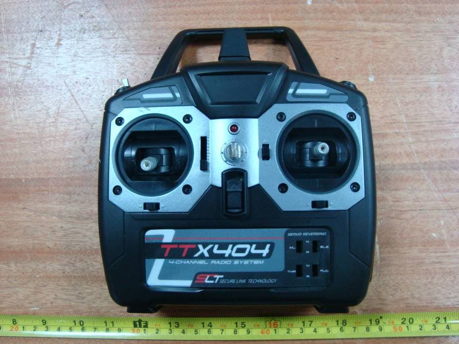
Click to zoom
Application Details
- Equipment Class
- DSS - Part 15 Spread Spectrum Transmitter
- Date of Grant
- Jan 22, 2011
- Application Purpose
- Original Equipment
- Date of Application
- Jan 22, 2011
- Equipment Note
- 2.4 GHz Radio System Transmitter
- Frequency Range
- 2403.00000000 - 2480.00000000
- Company
- Hobbico Inc
- Country
- United States
Documents & Files
Document Text
Text extracted from the exhibit documents filed with the FCC. Open a document above to read the original.
Users Manual
The Tactic TTX404 airplane radio system uses an advanced 2.4GHz spread spectrum technology to prevent unwanted outside interference from interrupting control of the model, ensuring error-free fl ying and eliminating the need to pull frequency pins before every fl ight. Tactic 2.4GHz transmitters and receivers are not compatible with other brands of 2.4GHz equipment. For safe operation and best results, it’s strongly recommended to read this manual in its entirety before use! Also read and understand the instructions included with the model. Damage resulting from misuse or modifi cation will void your warranty. FEATURES Trainer Switch LED Power Indicator Power Switch Reversing Switches Neck Strap Eyelet Trim Lever Charge Jack ● 2.4GHz spread spectrum technology ● Built-in failsafe & wireless trainer function ● Includes tiny, lightweight Tactic 6-channel receiver ● Analog & digital trims with servo reversing ● Transmitter binds to multiple Tactic 2.4GHz receivers ● Power status LED & built-in charge jack INSTRUCTION MANUAL TACJ2404 v2.2 2.4GHz 4-Channel Spread Spectrum Radio ™ 2 TTX404 TRANSMITTER ( Tx ) The TTX404 airplane transmitter is available in either a “Mode 2” confi guration with throttle on the left and elevator on the right, or “Mode 1” confi guration with throttle on the right and elevator on the left. Mode 2 radios are most commonly used in the U.S., whereas Mode 1 radios are popular in other countries. Be sure the radio purchased is of the correct mode. Four “AA” batteries are required to power the Tx (not included). Non-rechargeable 1.5V alkaline, or 1.2V rechargeable nickel-cadmium (NiCd) or nickel-metal hydride (NiMH) cells, can be used. Do not mix cell types, or old and new cells, etc. See the SERVOS AND ACCESSORIES section on page 16 for optional batteries available at local hobby retailers. To install the batteries, slide the battery door down. Insert the cells as shown in the diagram, making sure to note proper polarity for each cell. Close the battery door. POWER SWITCH, LED, and LOW BATTERY ALARM The red power LED should light when the power switch is moved upwards to the “ON” position. The 3 Tx should have adequate power for fl ight when the LED is on constantly. Anytime the LED begins to fl ash, accompanied by the sounding of an audible tone, the Tx battery voltage has dropped too low and operation of the model should NOT be attempted! WARNING! Never operate an R/C model with weak Tx batteries! Reduced operational range and/or possible loss of control of the aircraft could result. Replace weak alkaline batteries, or re-charge NiCd or NiMH batteries before attempting a fl ight! If during a fl ight the Tx LED starts to fl ash, accompanied by the sounding of audible tones, it’s a warning that the Tx batteries have become weak and the aircraft should be landed as soon as possible! AILERON (CH1) Controls the moveable surfaces at the end of both main wings to rotate the airplane about the “roll” axis (an imaginary line which extends from the airplane’s nose to the tail). Since every airplane is different, the aileron reversing switch must be set so that moving the aileron stick to the right will cause the airplane’s right aileron to defl ect up, thus causing the right wing to drop and the airplane will bank to the right. Moving the aileron stick to the left will cause the airplane’s left wing to drop and the airplane will bank to the left. This is one important method for turning the aircraft. ELEVATOR (CH2) Controls the moveable horizontal surfaces on the airplane’s tail to rotate the airplane about the “pitch” axis (an imaginary line extending through the center of both main wings, from one wing tip to the other wing tip). Position the elevator reversing switch so that pulling the elevator stick back (towards you) will cause the elevators to defl ect up, thus causing the nose of the airplane to rise. Pushing the elevator stick forwards (away from you) will cause the nose of the airplane to drop. When using the ailerons to bank the airplane’s wings, pulling the elevator stick back will help the aircraft maintain altitude and turn the aircraft more quickly. THROTTLE (CH3) Controls the speed (R.P.M.) at which the engine or electric motor operates. With the throttle reversing switch in the NOR position, pulling the throttle stick back will cause the engine’s speed to decrease. Pushing the throttle stick forward will cause the engine’s speed to increase. RUDDER (CH4) Controls the sideways movement of the airplane’s tail and will rotate the airplane about the “yaw axis” (an imaginary line from the top of the airplane’s fuselage to the bottom of the fuselage, located near the center-point of the fuselage). Position the rudder reversing switch so that moving the rudder stick to the right causes the rudder to defl ect to the right, thus causing the nose of the airplane to point to the right. Moving the rudder stick to the left will cause the nose of the airplane to turn 4 left. When using the rudder in conjunction with the ailerons, the airplane’s nose can point into a turn (instead of pointing up and “skidding” through the turn), allowing the airplane to perform tighter, more coordinated turns. TRIMS A “trim” lever is included for each of the main controls, located adjacent to the respective stick. The aileron, elevator, and rudder trim levers are digital in function, and always rest at center position. Briefl y defl ecting the lever to either direction away from center will cause the respective servo output to fi nely rotate to one direction, and will be accompanied by an audible tone. Pressing and holding the trim lever will cause the servo output to move repeatedly. During a fl ight, when the main sticks are released and spring back to center position, the aircraft should ideally not veer in any direction. If the aircraft does veer in a particular direction, click the respective trim lever until the aircraft maintains a straight attitude on its own. The throttle trim lever …
Text truncated - open the document above for the full version.
Cover Letter(s)
Hobbico, Inc. Add :2904 Research Road Champaign,Illinois,USA Tel:001- 217-398-3630 Fax:001-217-398-0008 - 1 - Product Similarity Declaration We, Hobbico Inc, authorize Bay Area Compliance Laboratories Corp. do test for our 2.4G radio control system: TTX404 mode1 and mode2; and for our business requirement, we declare that for this product we have made some hardware change. the differences between TTX404 mode1 and TTX404 mode2 details as below. 1 Appearance TTX404 mode1 a. Throttle stick and its trim lever on the right. b. Trainer switch on the right (over the throttle stick) c. Elevator stick and its trim lever on the left TTX404 mode2 a. Throttle stick and its trim lever on the left b. Trainer switch on the left (over the throttle stick) c. Elevator stick and its trim lever on the right 2 PCB The element position corresponding have a little change. Please help to deal with it ,and let me know if you have any question. Signature: Contact Person: ZHENMIN ZHOU Title: Product Development Company: Hobbico, Inc.
External Photos
EXHIBIT B - EUT EXTERNAL PHOTOGRAPHS TTX404 mode 1: EUT – Front View EUT – Rear View EUT – Side View 1 EUT – Side View 2 TTX404 mode 2: EUT – Front View EUT – Rear View EUT – Up View EUT – Bottom View
ID Label/Location Info
EXHIBIT A - FCC ID LABELING AND LOCATION FCC ID Label & Warning Statement FCC ID Location The label shown shall be permanently affixed at a conspicuous location on the device and be readily visible to the user at the time purchase (Labeling requirements per 2.925) Warning hereLabel here TTX404 mode 1 TTX404 mode 2 Warning here Label here
Internal Photos
EXHIBIT C - EUT INTERNAL PHOTOGRAPHS TTX404 mode 1: EUT – Cover Off View EUT – Main Board shielded Top View EUT – Main Board shielded off Top View EUT –Main Board Bottom View TTX404 mode 2: EUT – Battery Box View EUT – Cover Off View EUT – Main Board shielded Top View EUT – Main Board shielded off Top View EUT –Main Board Bottom View
RF Exposure Info
Hobbico, Inc. FCC ID: IYFTTX404B Report No.: RSZ10110514 Page 9 of 34 FCC Part15.247 Test Report FCC §15.247 (i) & §1.1307 (b) (1) & §2.1091- MAXIMUM PERMISSIBLE EXPOSURE (MPE) Standard Applicable According to subpart 15.247 (i) and subpart 1.1307 (b)(1), 2.1091 systems operating under the provisions of this section shall be operated in a manner that ensures the public is not exposed to RF energy level in excess of the communication guidelines. Limits for General Population/Uncontrolled Exposure Limits for General Population/Uncontrolled Exposure Frequency Range (MHz) Electric Field Strength (V/m) Magnetic Field Strength (A/m) Power Density (mw/cm 2 ) Averaging Time (Minutes) 0.3-1.34 614 1.63 *(100) 30 1.34-30 824/f 2.19/f *(180/f 2 ) 30 30-300 27.5 0.073 0.2 30 300-1500 / / f/1500 30 1500-100,000 / / 1.0 30 f = frequency in MHz * = Plane-wave equivalent power density Test Data Predication of MPE limit at a given distance S = PG/4πR² Where: S = power density (in appropriate units, e.g. mW/cm 2 ) P = power input to the antenna (in appropriate units, e.g., mW). G = power gain of the antenna in the direction of interest relative to an isotropic radiator, the power gain factor, is normally numeric gain. R = distance to the center of radiation of the antenna (appropriate units, e.g., cm) Maximum peak output power at antenna input terminal: 16.75 (dBm) Maximum peak output power at antenna input terminal: 47.30(mW) Prediction distance: >20 (cm) Predication frequency: 2403 (MHz) Antenna Gain (typical): 2 (dBi) Maximum Antenna Gain: 1.58 (numeric) The worst case is power density at predication frequency at 20 cm: 0.015 (mW/cm 2 ) MPE limit for general population exposure at prediction frequency: 1.0 (mW/cm 2 ) Result: The predicted power density level at 20 cm is 0.015 mw/cm 2 which is below the uncontrolled exposure limit of 1.0 mw/cm 2 , The EUT is used at least 20 cm away from user’s body. It is determined as mobile equipment and complies with the MPE limit.
Test Report
Note: This test report is prepared for the customer shown above and for the device described herein. It may not be duplicated or used in part without prior written consent from Bay Area Compliance Laboratories Corp. This report must not be used by the customer to claim product certification, approval, or endorsement by NVLAP*, NIST, or any agency of the Federal Government. * This report may contain data that are not covered by the NVLAP accreditation and are marked with an asterisk “*” (Rev.2) FCC PART 15.247 MEASUREMENT AND TEST REPORT For Hobbico, Inc. 2904 Research Road, Champaign, Illinois 61826, USA FCC ID: IYFTTX404B Report Type: Original Report Product Type: 2.4 GHz FHSS TRANSMITTER Test Engineer: Leon Chen Report Number: RSZ10110514 Report Date: 2010-12-22 Reviewed By: Merry Zhao EMC Engineer Prepared By: Bay Area Compliance Laboratories Corp. (Shenzhen) 6/F, the 3rd Phase of WanLi Industrial Building, ShiHua Road, FuTian Free Trade Zone Shenzhen, Guangdong, China Tel: +86-755-33320018 Fax: +86-755-33320008 Hobbico, Inc. FCC ID: IYFTTX404B Report No.: RSZ10110514 Page 2 of 34 FCC Part15.247 Test Report TABLE OF CONTENTS GENERAL INFORMATION.......................................................................................................................................4 PRODUCT DESCRIPTION FOR EQUIPMENT UNDER TEST (EUT) .....................................................................................4 OBJECTIVE...................................................................................................................................................................4 RELATED SUBMITTAL(S)/GRANT(S).............................................................................................................................4 TEST METHODOLOGY..................................................................................................................................................4 TEST FACILITY.............................................................................................................................................................4 SYSTEM TEST CONFIGURATION ..........................................................................................................................6 DESCRIPTION OF TEST CONFIGURATION......................................................................................................................6 EUT EXERCISE SOFTWARE..........................................................................................................................................6 EQUIPMENT MODIFICATIONS.......................................................................................................................................6 LOCAL SUPPORT EQUIPMENT LIST AND DETAILS........................................................................................................6 EXTERNAL I/O CABLE..................................................................................................................................................6 CONFIGURATION OF TEST SETUP.................................................................................................................................6 BLOCK DIAGRAM OF TEST SETUP................................................................................................................................7 SUMMARY OF TEST RESULTS ...............................................................................................................................8 FCC §15.247 (i) & §1.1307 (b) (1) & §2.1091- MAXIMUM PERMISSIBLE EXPOSURE (MPE)..............................9 STANDARD APPLICABLE..............................................................................................................................................9 TEST DATA..................................................................................................................................................................9 FCC §15.203 - ANTENNA REQUIREMENT...........................................................................................................10 APPLICABLE STANDARD............................................................................................................................................10 ANTENNA CONNECTOR CONSTRUCTION....................................................................................................................10 FCC §15.209, §15.205 & §15.247(d) - SPURIOUS EMISSIONS.............................................................................11 APPLICABLE STANDARD............................................................................................................................................11 MEASUREMENT UNCERTAINTY..................................................................................................................................11 EUT SETUP................................................................................................................................................................11 EMI TEST RECEIVER & SPECTRUM ANALYZER SETUP..............................................................................................12 TEST EQUIPMENT LIST AND DETAILS.........................................................................................................................12 TEST PROCEDURE......................................................................................................................................................12 CORRECTED AMPLITUDE & MARGIN CALCULATION.................................................................................................12 TEST RESULTS SUMMARY..........................................................................................................................................13 TEST DATA................................................................................................................................................................13 FCC §15.247(a) (1) - CHANNEL S…
Text truncated - open the document above for the full version.
Test Setup Photos
EXHIBIT D - TEST SETUP PHOTOGRAPHS Below 1 GHz: Radiated Emissions - Front View Below 1 GHz: Radiated Emissions - Rear View Above 1 GHz: Radiated Emissions - Front View Above 1 GHz: Radiated Emissions - Rear View
Contact Information
Applicant
Neal Cloud(Senior Product Manager)
Test Firm
Bay Area Compliance Laboratory Corp. (Shenzhen)John Chan
Technical Specifications
| # | Rule Parts | Frequency Range | Power Output |
|---|---|---|---|
| 1 | 15C | 2.40 GHz - 2.48 GHz | 47.30 mW |
Other Applications from Hobbico Inc
IYFZ1000
Oct 08, 2015wifi module (only for the camera)
Equipment Class
DTS - Digital Transmission System
IYFFPVT1
Sep 28, 2015Tactic FPV-T1 5.8GHz 25mW Transmitter
Equipment Class
DXX - Part 15 Low Power Communication Device Transmitter
IYFRVLC01
Sep 08, 2015Radio Control Toy Transmitter (2.4GHz)
Equipment Class
DXX - Part 15 Low Power Communication Device Transmitter
IYFDIDJ1001
Aug 28, 2015D103
Equipment Class
DSS - Part 15 Spread Spectrum Transmitter
IYFMR100
Jul 01, 2015Radio controlled model quadcopter and transmitter/receiver
Equipment Class
DXX - Part 15 Low Power Communication Device Transmitter