IYGPTB800
Spectralink Corporation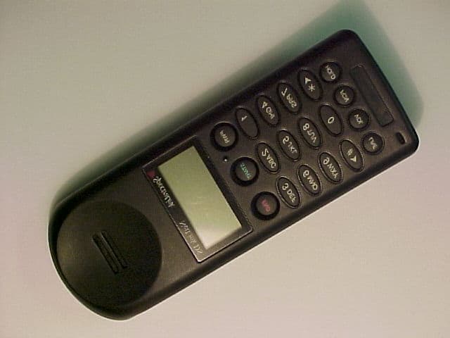
Click to zoom
Application Details
- Equipment Class
- DSS - Part 15 Spread Spectrum Transmitter
- Date of Grant
- Nov 15, 2001
- Application Purpose
- Original Equipment
- Date of Application
- Sep 05, 2001
- Frequency Range
- 2412.00000000 - 2462.00000000
- Company
- Spectralink Corporation
- Country
- United States
Documents & Files
Document Text
Text extracted from the exhibit documents filed with the FCC. Open a document above to read the original.
Users Manual
Using The NetLink Wireless Telephone The Wireless Telephone Headset SpectraLink offers optional headsets for use in noisy environments or if you need to have your hands free while talking on the Wireless Tele- phone. To use the headset, simply plug it into the jack on the side of the Wireless Telephone. The headset is specially designed to work properly with The NetLink Wireless Telephone. We do not recom- mend using other headsets. Answer A Call To answer a call when your headset is plugged in, press any key except PWRor END. Low Headset Volume The volume level can be adjusted separately for headset use. Plug the headset in and press FCN until VOLUMEdisplays. Use the keypad to enter a volume level from 1 (softest) to 8 (highest). This sets the low volume. High volume is auto- matically set two levels higher than low volume. Toggle between high and low volume by press- ing the VOLkey while in a call. About Battery Packs The Wireless Telephone will need to have its Battery Pack recharged periodically. The Nickel Metal Hydride (NiMH) rechargeable Wireless Telephone Battery Pack gives you four hours of talk time or 80 hours of stand-by time. Stand-by time is when the Wireless Telephone is turned on, but you are not using it. The Wireless Telephone also supports a Nickel- Cadmium (NiCd) battery pack, which supports two hours talk time and 40 hours stand-by. Indications of Low Battery The Wireless Telephone will notify you when the charge on the Battery Pack becomes low. If the Wireless Telephone is in use, the BATTmes- sage will display and you will hear a soft beep through the earpiece every six seconds. You have two minutes to complete the call or change the Battery Pack The Battery Pack can be changed while the call is still in progress. Do not press END. Quickly re- move the discharged Battery Pack and replace with a charged Battery Pack, press PWR, and then press STARTto resume the call in progress. If the Wireless Telephone is idle, you will hear a brief modulated ring signal and the Low Battery message will display. Your Wireless Telephone will not operate until you replace the Battery Pack. Depending on the charging equipment you have purchased, you will either place the Wireless Telephone in a Charging Stand to charge the Bat- tery Pack, or you will remove the Pack from the Wireless Telephone and install it in the charger. Headset and Battery Packs Removing and Replacing the Battery Pack on the Wireless Telephone To remove the Battery Pack, press down on the oval button above the Battery Pack on the back of the Wireless Telephone. Slide the Pack toward the bottom of the Wireless Telephone until it stops, then lift up. To replace the Battery Pack, first properly align the top of the Battery Pack with the arrows on the label on the back of the Wireless Telephone. Gently press and slide the Pack toward the top of the Wireless Telephone until it snaps into place. You should not have to force it against the Wire- less Telephone. Take care not to short the battery contacts on the pack with metal objects such as coins, keys or paper clips. Shorting the contacts can cause per- manent damage. Charging the Wireless Telephone Chargers are shipped with the appropriate power supply for the site's location. Connect the Stand or Charger to an appropriate wall outlet via its power supply and it's ready for use. Chargers op- erate in a 50° to 85° F (10° to 30° C) environ- ment. Do not expose them to freezing tempera- tures or direct sunlight. The Dual Charging Stand The SpectraLink Dual Charging Stand is a two- slot desktop charger designed to charge the Nick- el Metal Hydride (NiMH) Battery Packs required to operate Wireless Telephones. Full charging is accomplished in approximately two hours. Only NiMH Battery Packs with a YELLOW label on the handset contact side may be charged in the Dual Charging Stand. Older Battery Packs with a GREEN label will not charge. If the indicator light is fast flashing with a Battery Pack or handset in the slot, check to make sure the Battery Pack has a YELLOW label. • Before you use the Wireless Telephone, the Battery Pack must be charged. See Battery Packs. • You can only use the Wireless Telephone with your facility's telephone system. It is not a public cellular phone. • The PWRkey turns the Wireless Telephone on and off. The START and ENDkeys begin and end calls. When you finish a call, press the END key, not the PWRkey. • Keep the Wireless Telephone away from your ear when it is ringing. • The microphone is in the Wireless Tele- phone's lower right corner. This is a sensitive microphone that works well when the telephone is correctly posi- tioned on your ear. There is no need to speak directly into the microphone, but do not cover it with your hand or cheek when talking on the Wireless Telephone. • The Wireless Telephone's LCD panel displays information about the status of your Wireless Telephone and prompts you about features. • If the Wireless Telephone's Battery Pack is low, you will hear a soft beep and see the BATTor LOW BATTERY message in the display. • Improper disposal of Battery Packs can damage the environment. Dispose of batteries properly. • You can control the Wireless Tele- phone's volume level and the type of ring. See Setting User Preferences. • To protect the Wireless Telephone, use a carrying case. Tips For Use This section applies to the Wireless Telephone, Dual Charging Stand and the Quick Charger equally. The Wireless Telephone and Chargers have been designed to withstand the wear and tear of normal use; however, avoid dropping the Wireless Telephone or knocking it against hard surfaces. Carrying the Wireless Telephone in a holster or carrying case will help to protect it. There are no serviceable parts in the Wireless Telephone or Chargers. You should not open the Wireless Telephone case nor disassemble the Chargers. Doing so will void your warranty. Turn off the Wireless Telephone and unplug the Charger before you clean them. Never immers…
Text truncated - open the document above for the full version.
Attestation Statements
SpectraLink Corporation 5755 Central Avenue Boulder, Colorado 303.440.5330 fax 303.440.5331 www.spectralink.com F C C A U T H O R I Z A T I O N Date: August 10, 2001 Time: 09:07 To:FCC Authorization & Evaluation Division 7435 Oakland Mills Road Columbia, MD 21045-0429 From: Steven Maddy Phone: 303/583-5229 Director of RF Engineering F ax: 303/443-1746 Applicant: SpectraLink Corporation E-Mail: [email protected] ________________________________________________________________________ Dear Ladies and/or Gentlemen: I appoint Kenneth L. Boston and James Blaha at L.S. Compliance, Inc., to act as an agent in the preparation of applications under Part 15 of the rules and regulations of the Federal Communications Commission. I certify that the exhibitions properly describe the device being submitted under this application and will implement any changes described in the test report. The labels described will be affixed to each item. The following statement is required by the Federal Communications Commission: By checking Yes , the applicant certifies that, in the case of an individual applicant, he or she is not subject to a denial of federal benefits, that included FCC benefits, pursuant to section 5301 of the Anti-Drug Abuse Act of 1988, 21 U.S.C 853(a), or, in the case of a non-individual applicant (e.g. corporation, partnership, or other unincorporated association), no party to the application is subject to a denial of federal benefits, that includes FCC benefits, pursuant to that section. ___X___YES_______NO Dated this ___10 th ___day of __August__, 2001 By: Steven Maddy Title: Director of RF Engineering / SpectraLink Corporation Phone: 303/583-5229
Attestation Statements
August 24, 2001 FEDERAL COMMUNICATIONS COMMISSION 7435 Oakland Mills Road Columbia, MD 21046 Subject: Request for Non disclosure for FCC ID: IYGPTB800 To Whom It May Concern: Pursuant to 47 CFR Section 0.459, SpectraLink Corporation hereby requests non disclosure and confidential treatment of the following materials submitted in support of FCC certification application for FCC ID IYGPTB800: a. Schematic diagrams b. Operational description c. Block diagram Above materials contain trade secrets, proprietary and technical information which would customarily be guarded from competitors under 47 CFR section 0.457(d)(2). Disclosure or publication of any portion of this company confidential material to other parties could cause substantial competitive harm and provide unjustified benefits for competitors. SpectraLink Corporation understands that pursuant to 47 CFR section 0.457(d)(1)(ii) disclosure of the applicant and all accompanying documentation will not be made before the date of the grant. Sincerely yours, Steven L. Maddy Director of RF Engineering
External Photos
SpectraLink Corporation 2.4 Wireless Phone FCC ID#: IYGPTB800 Photo One Front Cover with Keypad of Wireless Phone
External Photos
SpectraLink Corporation 2.4 Wireless Phone FCC ID#: IYGPTB800 Photo Two Back Cover with Battery Source removed showing FCC and other Labels
External Photos
SpectraLink Corporation 2.4 Wireless Phone FCC ID#: IYGPTB800 Photo Three Close-up of FCC ID Label
External Photos
SpectraLink Corporation 2.4 Wireless Phone FCC ID#: IYGPTB800 Photo Four Another view of Product Labels
ID Label/Location Info
1.674 .845 SpectraLink, Inc. 1650 38th St., Ste 202E, Boulder, CO 80301 Label, NetLink DS, FCC PTB800 Text size 4 pt, 5 pt, 5.5 pt, 6 pt and 6.5 pt Font Times Note:Some text has a baseline shift of -1.0 pt. TOL: .XXX +/- .010 THK: .005 overall with adhesive MTL: Vinyl, White & Text Black 84-0263-00 REV A 1 OF 1 P/N: 84-0263-00 Rv A FCC ID: IYGPTB800 Spectralink Product No: PTB800 Made in the USA Refer to the User’s Guide for important regulatory information. 0263temp.qxd 8/10/01 8:56 AM Page 1
Internal Photos
SpectraLink Corporation 2.4 Wireless Phone FCC ID#: IYGPTB800 Photo Five Open for Inspection
Internal Photos
SpectraLink Corporation 2.4 Wireless Phone FCC ID#: IYGPTB800 Photo Six PCB removed to expose Keys and PCB Key Pad
Internal Photos
SpectraLink Corporation 2.4 Wireless Phone FCC ID#: IYGPTB800 Photo Seven PCB removed to expose RF side. Left picture shows RF Circuit Shielding, Right Photo shows Shielding removed
Internal Photos
SpectraLink Corporation 2.4 Wireless Phone FCC ID#: IYGPTB800 Photo Eight RF PCB Close-up Lower Circuitry
Internal Photos
SpectraLink Corporation 2.4 Wireless Phone FCC ID#: IYGPTB800 Photo Nine RF PCB Close-up Upper Circuitry
Test Report
. . . . . . . . . . . . . . . . . . . L. S. Compliance, Inc. Compliance Testing of: Spectra Link DS-11MB Spread Spectrum Transmitter Prepared for: Spectra Link Test Report Number: 301299-TX Date(s) of Testing: August 14 th , 15 th , 16 th and 20 th , 2001 All results of this report relate only to the items that were tested.All results of this report relate only to the items that were tested. This report may not be reproduced, except in full, without written approval of L. S.This report may not be reproduced, except in full, without written approval of L. S. Compliance, Inc.Compliance, Inc. L. S. Compliance, Inc. W66 N220 Commerce Court Cedarburg, Wisconsin 53012 Phone: 262 - 375 - 4400 Fax: 262 - 375 - 4248 L. S. COMPLIANCE, Inc. FCC ID: IYGPTB800FCC ID: IYGPTB800 LSC- 301299-DS-11MBPage 1 of 29 INDEXINDEX SectioSectio nn DescriptionDescription PagePage ## Index1 Description of Measurement Facilities2 Signature Page3 1.3Summary of Test Report4 1.4Introduction4 1.5Purpose5 1.6Conducted Emissions5 1.7Radiated Emission Test Setup6 1.8Radiated Emission Test Procedure6 1.9Test Equipment Utilized7 1.10Restricted Bands Affected8 1.11Photos taken of testing9 1.12Summary of Results and Conclusions12 1.13Test Equipment List13 Appendices ASample Calculations:14 i.Calculation of Radiated Emissions Limits15 BData Charts16 CGraphs19 DAttachment of conducted emissions28 L. S. COMPLIANCE, Inc. FCC ID: IYGPTB800FCC ID: IYGPTB800 LSC- 301299-DS-11MBPage 2 of 29 DESCRIPTION OF MEASUREMENT FACILITIES Site on File with the FCC ID Number: 31040/SIT 1300F2 Industry Canada listed site: IC 3088 “ The site referenced above has been found to comply with the test site criteria found in ANSI C63.4-1992 and 47CFR Section 2.948.” L. S. COMPLIANCE, Inc. FCC ID: IYGPTB800FCC ID: IYGPTB800 LSC- 301299-DS-11MBPage 3 of 29 L. S. COMPLIANCE, Inc. FCC ID: IYGPTB800FCC ID: IYGPTB800 LSC- 301299-DS-11MBPage 4 of 29 SIGNATURE PAGE Testing And Prepared By: August 28, 2001 Thomas T. Lee, EMC engineerDATE Testing By: August 28, 2001 Kenneth L. Boston PEDATE Reviewed and Approved by: August 28, 2001 Kenneth L. Boston, EMC Lab ManagerDate PE #31926 Registered Professional Engineer (State of Wisconsin) L. S. COMPLIANCE, Inc. FCC ID: IYGPTB800FCC ID: IYGPTB800 LSC- 301299-DS-11MBPage 5 of 29 1.3SUMMARY OF TEST REPORT MANUFACTURER:SpectraLink MODEL:DS-11MB SERIAL:pre-production unit DESCRIPTION:Spread spectrum data packet transceiver FREQUENCY RANGE:2400-2483.5 MHz The Spectra Link DS-11MB module was found to MEETMEET the radiated emission specification of Title 47 CFR FCC, Part 15, subpart C for an intentional radiator The Spectra Link DS-11MB module was also found to MEETMEET the radiated emission specification of Title 47 CFR, FCC Part 15, subpart B for emissions with regards to the receiver and digital sections of the product. This product is a composite device, with the digital sections subject to verification. Therefore this technical report will primary contain data that is pertinent to the certification of the transmitter section of the product. 1.4INTRODUCTION During August 14 th , 15 th , 16 th , 20 th , 2001, a series of Radiated Emissions tests were performed on the Spectra Link DS-11MB, a spread spectrum transceiver product, designed for use as a NetLink wireless telephone. These tests were performed using the test procedures outlined in ANSI C63.4-1992 for intentional radiators, and in accordance with the requirements set forth in FCC Part 15.247 for a spread spectrum transmitter. Tests were also performed as outlined in ANSI C63.4-1992 for non-intentional radiators, in order to verify compliance with the limits set forth in part 15.109 for and to allow verification of emissions for the digital section of the product. These tests were performed by Kenneth L. Boston, PE, and Thomas T. Lee of L. S. Compliance, Inc. L. S. COMPLIANCE, Inc. FCC ID: IYGPTB800FCC ID: IYGPTB800 LSC- 301299-DS-11MBPage 6 of 29 1.5PURPOSE The above mentioned tests were performed in order to determine the compliance of the Spectra Link DS-11MB transceiver with limits contained in various provisions of Title 47 CFR, FCC Part 15, including: 15.20715.247b15.247e 15.20515.247c15.109 15.247a215.247d Various of these tests, including the conducted RF out the antenna port and the jamming margin test are contained in additional sections of the test report that are appended. All radiated emissions tests were performed to measure the emissions in the frequency bands described by the above sections, and to determine whether the emissions are below the limits established by the above sections. These tests were performed in accordance with the procedure described in the American National Standard for methods of measurement of Radio-Noise Emissions from Low-Voltage Electrical and Electronic Equipment in the Range of 9 kHz to 40 GHz (ANSI C63.4-1992). Another document used as reference for the EMI receiver specification was the International Special Committee on Radio Interference (CISPR) number 16-1 (1993). 1.6Conducted (AC Mains) Test and measurements The Conducted Emission tests were not performed due to the device being a battery operated product. 1.7RADIATED EMISSIONS TEST SETUP The test sample was operated within the 3 meter Semi-Anechoic, FCC listed chamber located at L.S. Compliance in Cedarburg, WI. The sample was positioned on a small wood pedestal, which was centered on the flush-mounted 2m diameter metal turntable. The test sample was operated on a single Nickel Metal Hydride battery at 5.0VDC. The test sample was configured to run in a continuous transmit mode during the 15.247 and 15.205 measurements. The test sample was set to operate on either channel 1 (low), channel 6 (medium) or channel 11 (high) while being tested as an intentional radiator, in order to determine compliance within a frequency range of 2400-2483.5 MHz, as dictated by FCC part 15.31m. The Spectra Link DS-11MB module was mounted on a small plexi-glass support posted on the 80 CM h…
Text truncated - open the document above for the full version.
Test Report
W66 N220 Commerce Court, Cedarburg, Wisconsin 53012 • 262-375-4400 • FAX 262-375-4248 Email: [email protected] http://www.lsr.com/ .......... . . . . . . . . . . L. S. COMPLIANCE, Inc. SpectraLink : Appendix D to Report Number 301299-TX FCC ID: IYGPTB800 Part 15.247 Type Acceptance, Conducted Measurements Prepared for: Spectra Link Revision 1.0 L. S. COMPLIANCE, Inc. Page 2 of 38 _______________________________________________________________________________________FCC ID: IYGPTB800 W66 N220 Commerce Court, Cedarburg, Wisconsin 53012 • 262-375-4400 • FAX 262-375-4248 Email: [email protected] http://www.lsr.com/ Table of Contents I.Project Information.................................................................................................................................................................3 II.Declaration of Compliance – 15.247 Measurement Summary...................................................................................5 A.Part 15.247 (a)(2) Minimum Emission 6 dB Bandwidth........................................................................................5 B.Part 15.247 (b) (1) Maximum Conducted Emission Output Power......................................................................5 C.Part 15.247 (c) Minimum Relative Spurious Power Spectral Density Level.......................................................6 D.Part 15.247 (d) Maximum Power Spectral Density.................................................................................................7 III.FCC Conducted Measurements.......................................................................................................................................7 A.Part 15.247.......................................................................................................................................................................7 1.15.247 (a) (2) Emission 6 dB Bandwidth...................................................................................................................7 2.15.247 (b) (1) Output Power.......................................................................................................................................14 3.15.247 (b) (3) Effective Radiated Power..................................................................................................................20 4.15.247 (c) Spurious Modulation Products...............................................................................................................20 5.15.247 (d) Power Spectral Density...........................................................................................................................29 IV.Critical Equipment List...................................................................................................................................................38 V.Equipment Uncertainties.................................................................................................................................................38 L. S. COMPLIANCE, Inc. Page 3 of 38 _______________________________________________________________________________________FCC ID: IYGPTB800 W66 N220 Commerce Court, Cedarburg, Wisconsin 53012 • 262-375-4400 • FAX 262-375-4248 Email: [email protected] http://www.lsr.com/ SpectraLink DS_11MB I. Project Information Project: Spectra Link DS_11MB Spectra Link Contact: Company: Spectra Link Full Name: John Chabon Title: System Engineer Bus: (303)-440-5330 Or (1800)-676-5465 E-mail: [email protected] LS Compliance Contact: Kenneth L. Boston, Lab Manager Thomas T. Lee, Senior EMC Engineer Voice:262-375-4400 Fax:262-375-4248 Email:[email protected] Report Date:9/7/01 Revision:1.0 Proposal #: Proposal File:301299-TX Job Number: L. S. COMPLIANCE, Inc. Page 4 of 38 _______________________________________________________________________________________FCC ID: IYGPTB800 W66 N220 Commerce Court, Cedarburg, Wisconsin 53012 • 262-375-4400 • FAX 262-375-4248 Email: [email protected] http://www.lsr.com/ SIGNATURE PAGE Testing By: August 23, 2001 Thomas T. Lee, EMC engineer DATE Prepare By: August 23, 2001 Thomas T. Lee, EMC engineer DATE Reviewed and Approved By August 23, 2001 Kenneth L. Boston, EMC Lab Manager Date PE #31926 Registered Professional Engineer (State of Wisconsin) L. S. COMPLIANCE, Inc. Page 5 of 38 _______________________________________________________________________________________FCC ID: IYGPTB800 W66 N220 Commerce Court, Cedarburg, Wisconsin 53012 • 262-375-4400 • FAX 262-375-4248 Email: [email protected] http://www.lsr.com/ II. Declaration of Compliance – 15.247 Measurement Summary Presented below is a compliance matrix showing the test conditions, test indications, test limits and test outcomes associated with the part 15.247 conducted tests performed on the Equipment Under Test: Spectra Link DS_11MB. A. Part 15.247 (a)(2) Minimum Emission 6 dB Bandwidth FCC Test Type EUT Test Conditions 15.247 (a) (2)15.247 (a) (2)15.247 (a) (2) LimitIndicationOutcome Channel 1 (2412 MHz), 11 Mbps500 kHz, min10.6 MHzPASS Channel 6 (2437 MHz), 1 Mbps 500 kHz, min 7.98 MHzPASS Channel 6 (2437 MHz), 5.5 Mbps500 kHz, min9.85 MHzPASS Channel 6 (2437 MHz), 11 Mbps500 kHz, min10.1 MHzPASS Channel 11 (2462MHz), 11 Mbps 500 kHz, min 9.35 MHzPASS B. Part 15.247 (b) (1) Maximum Conducted Emission Output Power FCC Test Type EUT Test Conditions 15.247 (b) (1)15.247 (b) (1)15.247 (b) (1) LimitIndicationOutcome Channel 1 (2412 MHz), 11 Mbps30 dBm, Max15.0 dBmPASS Channel 6 (2437 MHz), 1 Mbps 30 dBm, Max 14.9 dBmPASS Channel 6 (2437 MHz), 5.5 Mbps 30 dBm, Max15.3 dBmPASS Channel 6 (2437 MHz), 11 Mbps30 dBm, Max15.4 dBmPASS Channel 11 (2462MHz), 11 Mbps 30 dBm, Max 15.7 dBmPASS L. S. COMPLIANCE, Inc. Page 6 of 38 _______________________________________________________________________________________FCC ID: IYGPTB800 W66 N220 Commerce Court, Cedarburg, Wisconsin 53012 • 262-375-4400 • FAX 262-375-4248 Email: [email protected] http://www.lsr.com/ C. Part 15.247 (c) Minimum Relative Spurious Power…
Text truncated - open the document above for the full version.
Test Report
sl SpectraLink 11 Mb/s NetLink Phone Assy # 93-162-04 11 Mb/s Jammer Margin Testing Introduction The FCC rules require testing of Processing Gain for our 11 Mb/s NetLink phones. The applicable rules are: 47 CFR Ch. I § 15.247 (e) The processing gain of a direct sequence system shall be at least 10 dB. The processing gain represents the improvement to the received signal-to- noise ratio, after filtering to the information bandwidth, from the spreading/despreading function. The processing gain may be determined using one of the following methods: (1) As measured at the demodulated output of the receiver: the ratio in dB of the signal-to-noise ratio with the system spreading code turned off to the signal-to-noise ratio with the system spreading code turned on. (2) As measured using the CW jamming margin method: a signal generator is stepped in 50 kHz increments across the passband of the system, recording at each point the generator level required to produce the recommended Bit Error Rate (BER). This level is the jammer level. The output power of the intentional radiator is measured at the same point. The jammer to signal ratio (J/S) is then calculated, discarding the worst 20% of the J/S data points. The lowest remaining J/S ratio is used to calculate the processing gain, as follows: Gp = (S/N)o + Mj + Lsys, where Gp = processing gain of the system, (S/N)o = signal to noise ratio required for the chosen BER, Mj = J/S ratio, and Lsys = system losses. Note that total losses in a system, including intentional radiator and receiver, should be assumed to be no more than 2 dB. The product is based on the Intersil Prism chipset which has been demonstrated to pass the FCC processing gain tests. Procedure The unit was tested according to procedure (2) (CW Jamming Margin Method). The block diagram of the test setup is shown in Figure 1. IEEE-488 Bus RS-232 RS-232 Step Atten Combiner Test Transmitter Power Meter PC Contoller Test Receiver RF Signal Generator Circulator TERM Fig. 1. Block Diagram of Test Setup The Test Transmitter consists of an 11 Mb/s Netlink phone operating in a continuous packet transmit mode. The Test Receiver is an 11 Mb/s Netlink phone operating with special test code that reports received errors. A PC equipped with an IEEE-488 interface card was used to control both the RF Signal Generator (over the IEEE-488 interface) and the Netlink phones (over the RS-232 serial ports). The test code modes for the transmitter allowed for continuously transmitting a packet of information at a user specified rate (1, 2, 5.5 or 11 Mb/s). The step attenuator was adjusted to give approximately -50 dBm output power from the Test Transmitter at the Test Receiver. The test was performed on channel 6 (2437 MHz). A special test routine was written for the PC to automate the collection of data. The routine went through each frequency offset across the band (±8 MHz) and measured the jammer RF level required to generate >3.2% PER (see Appendix F). The jammer RF level was set to a resolution of 0.1 dB. The frequency and jammer RF level was written to a file for further processing in a spreadsheet. The power meter was used in a separate calibration measurement to account for the additional losses caused by the jammer combining network and to determine the transmitter output power. This was later applied to the raw collected data in the spreadsheet. And finally, the actual processing gain was calculated based on the formula: G p = S N o M j L sys Where:G p is the Processing Gain (in dB) (S/N) o is the required output Signal-to-Noise ratio for sensitivity (in dB) M j is the Jammer-to-Signal ratio (in dB) L sys is the allowed system implementation losses (in dB) Note: L sys is limited to 2dB. The (S/N) o value depends on the modulation rate that the test is run at. The values used for this test are: 1 Mb/s10.3 dB 2 Mb/s13.3 dB 5.5 Mb/s13.7 dB 11 Mb/s17.0 dB These values are based on documents provided by Intersil with reference to their Prism chip set detailing required S/N values as well as justification of the coding gain present in 5.5 and 11 Mb/s mode. References: 1."Testing for compliance with FCC rules 15-247e", Carl Andren, Intersil Corporation, January 11, 2000 2.Intersil WLAN PC Card, Model No: HWB3163, FCC ID: OSZ3163B1, Engineering Test Report - Appendix B, November 17, 1999 3.FCC Processing Gain report of 2.4 GHz WLAN Access point, Intersil, Model ISL36356A-SB, FCC ID: OSZ36356A2 Test Equipment Used Test TransmitterSpectraLink 93-0162-04B S/N: 610030702 Test ReceiverSpectraLink 93-0162-04C S/N: 610030698 RF Signal GeneratorHP E4421B RF Spectrum AnalyzerHP 8560B Power CombinerMiniCircuits ZESC-2-11 CirculatorNarda 4923 w/ SMA termination Step AttenuatorKay 839 Power MeterHP EPM-441A w/ ECP-E18A Sensor Summary of Results Ch #6 @ 1 Mb/s (S/N) o =10.3 dB M j =2.1 dB (at 20th percentile) L sys =2.0 dB G p =14.4 dB Ch #6 @ 2 Mb/s (S/N) o =13.3 dB M j =-0.3 dB (at 20th percentile) L sys =2.0 dB G p =15.0 dB Ch #6 @ 5.5 Mb/s (S/N) o =13.7 dB M j =-2.3 dB (at 20th percentile) L sys =2.0 dB G p =13.4 dB Ch #6 @ 11 Mb/s (S/N) o =17.0 dB M j =-7.5 dB (at 20th percentile) L sys =2.0 dB G p =11.5 dB The unit passes the required 10 dB requirement for all four transmission rates. Appendices Appendix A: Measured Data Ch #6 1 Mb/s Appendix B: Measured Data Ch #6 2 Mb/s Appendix C: Measured Data Ch #6 5.5 Mb/s Appendix D: Measured Data Ch #6 11 Mb/s Appendix E: Calibration Measurement Appendix F: Converting between Bit Error Rate and Packet Error Rate Appendix A: Measured Data Ch #6 1 Mb/s (S/N)o =10.3dB Mj =2.1dB @ 20th Percentile Lsys =2dB Gp =14.4dB FCC Jammer Test (Ch #6, 1 Mbps, 93-0162-04 Bd) 0.0 5.0 10.0 15.0 20.0 25.0 30.0 24292433243724412445 Frequency (MHz) Processing Gain (dB) 610030698, Auto, simplex measurement, 162-04 xmtr. 1Mb/s, Estimated BER s/w RawRawCorrectedCorrected XMITS.G.XMITS.G. FreqRF LevelRF LevelRF LevelRF LevelMj = J/SGp = (S/N)o + Mj + Lsys 2429.000-51.1-38.0-51.0-43.17.920.2 2429.050-…
Text truncated - open the document above for the full version.
Test Report
L. S. COMPLIANCE, Inc. FCC ID: IYGPTB 800 LSC- Spectralink DS-11MB Date: September 7,2002 Subject: SpectraLink Jamming margin document, DS-11MB FCC ID: IYGPTB800 A document prepared by SpectraLink, detailing the tests performed on the NetLink 11 MB phone for processing gain performance was reviewed by L S Compliance, and is hereby submitted to the FCC to show compliance with the 15.247 (e) requirement. The configuration shown in Figure 1 (block diagram) is consistent with the required set-up for the Jamming margin method of performing the test, and shows that the required measurements were performed on the system, which includes the receiver. The Test equipment used is listed in the report, and is assumed to have recent calibrations traceable to NIST. A system calibration was carried out before the test was performed, in order to ascertain the additional losses in the measurement system. (appendix E) The report illustrates the theoretical processing gain, and the calculated (S/N)o by references located in the text explanation given in the front of the documentation. The BER rate used for the comparison was taken as 10e\-5, and the corresponding packet rate was given in Appendix F. The measured Mj value at each data rate was chosen, as the worst case value found at the 20 th percentile point, as seen in the columnar data. The test was performed for 4 data rates, including the 11 MB rate, which is the highest data rate available. It is assumed that the test software has used a sound technique for determination of instantaneous and cumulative bit error rates as required for the measurement. Understanding that the implicit assumptions are easily referenced and traceable in the event of a…
Text truncated - open the document above for the full version.
Contact Information
Applicant
Perry Robbins(Principle Engineer)
Technical Contact
SpectraLink CorporationSteven Maddy
[email protected]303-583-5229
W66 N220 Commerce Court · Boulder, Wisconsin · United States
Non-Technical Contact
L. S. Compliance, Inc.James Blaha
[email protected]262-375-4400
Test Firm
LS Research, LLCRyan Urness
Technical Specifications
| # | Rule Parts | Frequency Range | Power Output |
|---|---|---|---|
| 1 | 15C | 2.41 GHz - 2.46 GHz | 100.00 mW |
Other Applications from Spectralink Corporation

IYG-K031A
Sep 16, 2024S37 DECT Handset
Equipment Class
PUE - Part 15 Unlicensed PCS portable Tx held to ear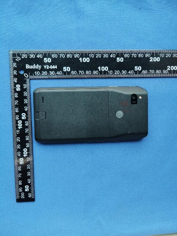
IYG97XX
Oct 06, 2023Wifi/BT Phone
Equipment Class
6XD - 15E 6 GHz Low Power Indoor Client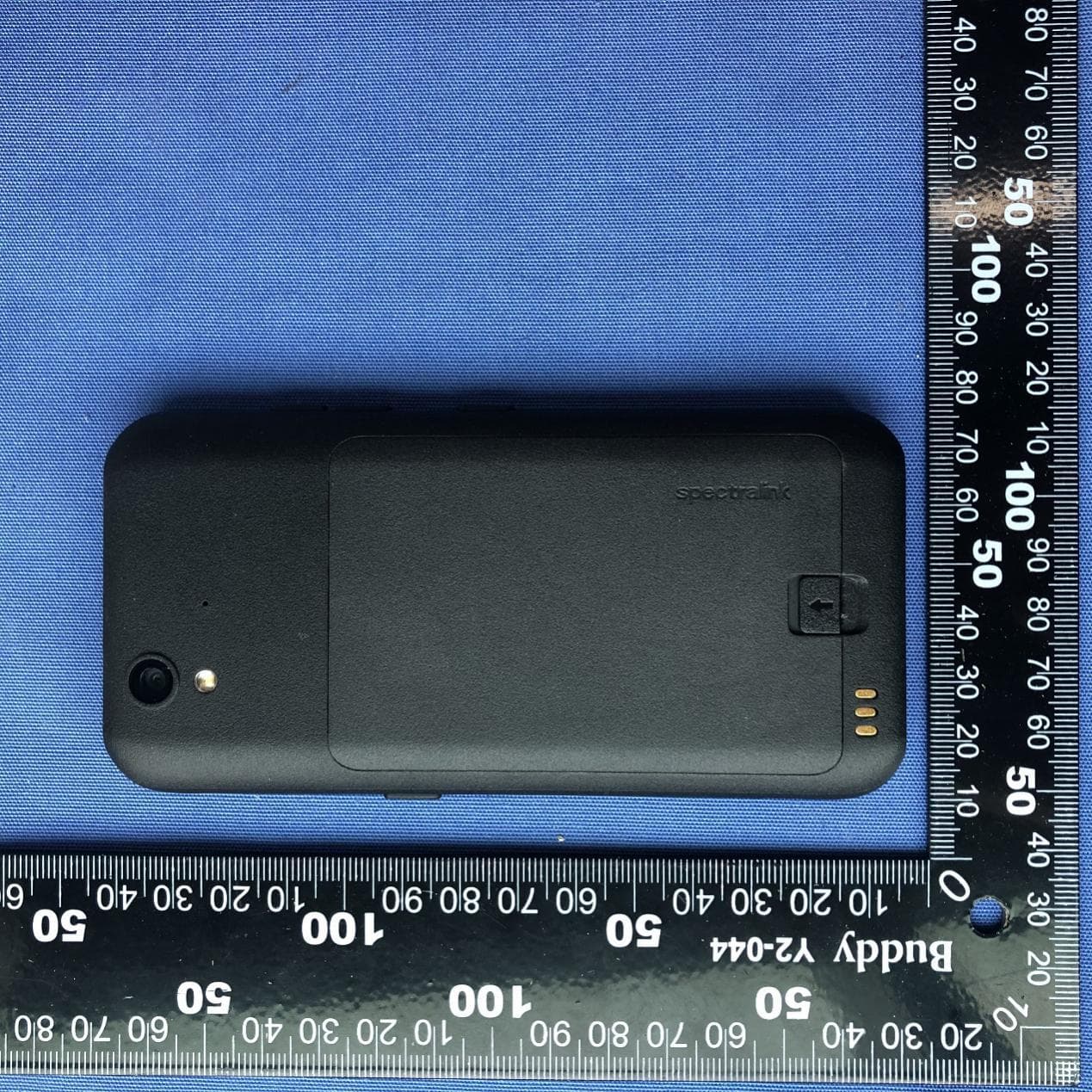
IYG9240
Nov 09, 2020Mobile Phone
Equipment Class
NII - Unlicensed National Information Infrastructure TX
IYG-875X
Feb 04, 2014Wireless IP Phone
Equipment Class
NII - Unlicensed National Information Infrastructure TX
IYGPTB450
Jul 26, 2007Wireless Telephone
Equipment Class
DSS - Part 15 Spread Spectrum Transmitter