IYGRNP2400802.11 Wireless Telephone Handset
Spectralink Corporation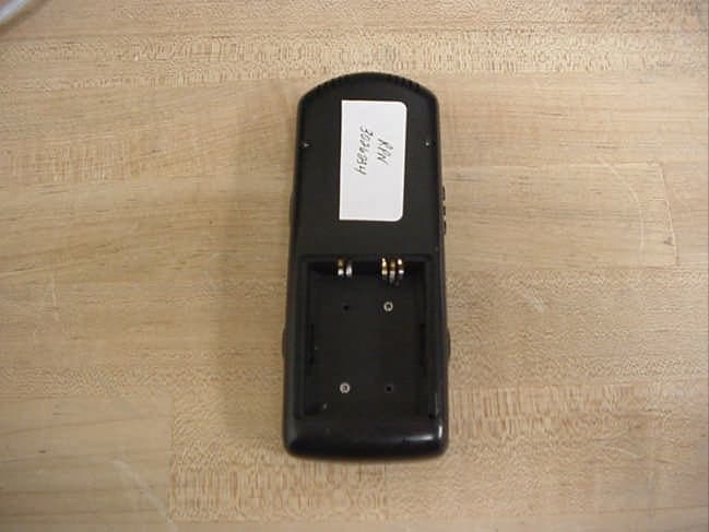
Click to zoom
Application Details
- Equipment Class
- DTS - Digital Transmission System
- Date of Grant
- Jun 04, 2003
- Application Purpose
- Original Equipment
- Date of Application
- Jun 04, 2003
- Equipment Note
- 802.11 Wireless Telephone Handset
- Frequency Range
- 2412.00000000 - 2462.00000000
- Company
- Spectralink Corporation
- Country
- United States
Documents & Files
Document Text
Text extracted from the exhibit documents filed with the FCC. Open a document above to read the original.
Users Manual
INSTRUCTIONS FOR USE Turn onPress and hold Power On/Start Call. Two chirps will sound. When the key is released, the in-service tone sounds. Turn offPress and hold Power Off/End Call. One chirp will sound. If in a call, hang up first, then turn off. Make a call orPress Power On/Start Call. go off hook Select linePress LINEand the number key corresponding to the required line. Dial numberPress number keys. Hang upPress Power Off/End Call. Be sure to do this at the end of each call. Answer callPress Power On/Start Call. Change volumeWhile in a call, press the Upor Downbutton. Silence whilePress the Power Off/End Callkey to silence the ring. ringing Headset answerPress any key (other than Power On/Start Call, Power Off/End Call, or a softkey) to answer a call when a headset is plugged in. Push-to-talkSelect the channel via User options. To broadcast your message, press and hold the radio control Push-to-talkbutton and speak into the microphone. *View ShortcutPress MENUwhile off hook to scroll through the Shortcut Menu. Press Up or Down to Menu highlight option, then press Selectto activate the feature. Press any shortcut key at any time while in the Shortcut Menu to activate feature. No shortcut indicates that the feature can only be accessed using a softkey. Press corresponding softkey to activate. To cancel out of Shortcut Menu and return to Main display press MENU. *View softkeyPress FCNwhile off hook to scroll through the softkey functions. Press FCNagain to scroll to functions the next set of options. Repeat as required. Press corresponding softkey to activate feature or press any shortcut key at any time to activate the corresponding feature. User optionsPress FCNwhile on hook to change settings (* shows current, follow display instructions to set): Ring Type—select: Normal (for an audible ring) Vib/norm (vibrates for 6 seconds, then rings) Vibrate (vibrates until answered) Current IP address: may not be edited. Extension number: may not be present for some protocols. Push-to-talk: Channel selection: 1-8: selects the channel used for two-way radio transmission and monitoring. Enable/Disable Additional options may be present. BacklightComes on when any key is pressed. Turns off after ten seconds if no key is pressed. Battery releaseSqueeze both battery release buttons simultaneously to release Battery Pack. Status/Tone Indicators No serviceAn alarm sounds and a descriptive message displays when the Wireless Telephone message cannot receive or place calls. You may be outside of the covered area. Walk back into the covered area. The in-service tone indicates service is re-established. The battery icon displays and a beep sounds to indicate the Battery Pack charge is low. You have two minutes to change the Battery Pack before losing power The voicemail icon indicates that you have a new voicemail message. *In certain system environments, the softkeys and the MENU key are unavailable. In such environments, press the FCN key while off hook to scroll through system features. Press the shortcut key to activate the feature. NOTE: •It is recommended that standard acceptance procedures be followed prior to operating this equipment in proximity of life-support systems. •To minimize risk of interference, pacemaker users should not carry the Wireless Telephone next to the pacemaker. •Earpiece may retain magnetic objects. •Operation of the Wireless Telephone may produce an audible noise noticeable to hearing aid users. It is recommended that a hearing aid compatible headset be used by hearing aid users. •This device complies with part 15 of the FCC Rules. Operation is subject to the following two conditions: (1) This device may not cause harmful interference, and (2) this device must accept any interference received, including interference that may cause undesired operation. BEDIENUNGSANLEITUNG EinschaltenHalten Sie die Taste Power On/Start Callgedrückt. Sie hören zwei Signaltöne. Wenn Sie die Taste loslassen, erklingt der Betriebston. AusschaltenHalten Sie die Taste Power Off/End Callgedrückt. Sie hören einen Signalton. Wenn Sie ein Gespräch führen, beenden Sie dies, bevor Sie das Telefon ausschalten. Telefonieren oderDrücken Sie die Taste Power On/Start Call. Hörer abheben LeitungDrücken Sie LINE, und wählen Sie die der gewünschten Leitung entsprechende Zifferntaste. auswählen Nummer wählenDrücken Sie die entsprechenden Zifferntasten. Hörer auflegenDrücken Sie die Taste Power Off/End Call. Achten Sie darauf, diese Taste am Ende jedes Gesprächs zu drücken. AnrufDrücken Sie die Taste Power On/Start Call. entgegennehmen Lautstärke ändernDrücken Sie während eines Gesprächs die Tasten Upoder Down. RuftonDrücken Sie die Taste Power Off/End Call, um den Rufton zu unterdrücken. unterdrücken AnrufannahmeDrücken Sie eine beliebige Taste (außer der Tasten Power On/Start Call, Power Off/End Call oder den mit Headset Softkey-Funktionstasten), um einen Anruf entgegenzunehmen, während ein Headset angeschlossen ist. Push-to-TalkWählen Sie über die Benutzeroptionen einen Kanal aus. Halten Sie zum Übertragen Ihrer Nachricht die Funktion Push-to-Talk-Taste gedrückt und sprechen Sie ins Mikrofon. *Shortcut-MenüHeben Sie den Hörer ab, und drücken Sie MENU, um durch das Shortcut-Menü zu blättern. anzeigen Drücken Sie Upoder Down, um eine Option zu markieren, und dann die Select-Taste, um die Funktion zu aktivieren. Wenn Sie sich im Shortcut-Menü befinden, können Sie jederzeit eine beliebige Shortcut-Taste drücken, um die Funktion zu aktivieren. Wird kein Shortcut angezeigt, bedeutet dies, dass die Funktion nur über eine Softkey-Taste aufgerufen werden kann. Drücken Sie die entsprechende Softkey-Taste, um die Funktion zu aktivieren. Um das Shortcut-Menü zu verlassen und zum Haupt-Display zurückzukehren, drücken Sie MENU. *Funktionen derHeben Sie den Hörer ab, und drücken Sie FCN, um durch die Funktionen der Softkey-Tasten zu blättern. Softkey-Tasten Drücken Sie erneut FCN, um zur nächsten Optionsgruppe zu wechseln. Wied…
Text truncated - open the document above for the full version.
Cover Letter(s)
Spectralink Corporation . 5755 Central Avenue . Boulder, CO 80301 Office 303.440.5330 Fax 303.443.1746 www.spectralink.com Letter of Confidentiality May 15, 2003 Federal Communications Commission 7435 Oakland Mills Road Columbia, MD 21046 Gentlemen: This letter is to comply with Section 0.549 pertaining to confidential material. SpectraLink, Corporation would like the following documents regarding this submission for FCC ID: IYGRNP2400 to be kept confidential. 1. Schematics 2. Block Diagram 3. Operating description The above material contains trade secrets or technical data, which would customarily be guarded from competitors. We do not want these documents to be accessible to the general public. Sincerely, Mark Angliss Quality & Process Engineering SpectraLink Corporation
External Photos
Page 1 of 2 Page 2 of 2
ID Label/Location Info
Catalog No.: PTX100 SpectraLink, Inc. 5755 Central Av., Boulder, CO 80301 Label,RNP, FCC,PTX100 Text size: 3 pt, 4 pt Font: Times New Roman TOL: .XXX +/- .010 THK: .005 overall with adhesive MTL: White & Text Black P/N: 84-0488-00 REV 01Page 1 of 1 1.325” .781” Assembled in Mexico MAC: 00:90:7A:00:D6:B6 See User Guide for Product Information SpectraLink Model # RNP2400 FCC ID: IYGRNP2400 CAN: XXXXXXXX examplePTX100lbl.qxd 4/16/03 10:52 AM Page 1
Internal Photos
Page 1 of 4 Page 2 of 4 Page 3 of 4 Page 4 of 4
RF Exposure Info
in accordance with the requirements of FCC Report and Order: ET Docket 93-62, and OET Bulletin 65 Supplement C for 2.4 GHz Direct Sequence Spread Spectrum Cordless Phone MODEL: RNP2400 FCC ID: IYGRNP2400 March 11, 2003 REPORT NO: 03U1863-1B Prepared for Spectralink Corporation 5755 Central Ave Boulder, CO 80301, USA Prepared by COMPLIANCE CERTIFICATION SERVICES 561F MONTEREY ROAD, MORGAN HILL, CA 95037, USA TEL: (408) 463-0885 REPORT NO: 03U1863-1B DATE: March 11, 2003 FCC ID: IYGRNP2400 COMPLIANCE CERTIFICATION SERVICES Page: 2 of 25 This report shall not be reproduced except in full, without the written approval of CCS. This document may be altered or revised by Compliance Certification Services personnel only, and shall be noted in the revision section of the document. CERTIFICATE OF COMPLIANCE (SAR EVALUATION) DATES OF TEST: March 10 - 11, 2003 REPORT NO: 03U1863-1B APPLICANT: Spectralink Corporation 5755 Central Ave Boulder, CO 80301, USA MODEL: RNP2400 FCC ID: IYGRNP2400 DEVICE CATEGORY: PORTABLE DEVICES EXPOSURE CATEGORY: GENERAL POPULATION/UNCONTROLLED EXPOSURE Test Sample is a: Production unit Modulation type: Direct Sequence Spread Spectrum (DSSS) Operating Mode: Maximum continuous output Tx Frequency: 2401 ~ 2482 MHz Max. O/P Power: 19.20 dBm (Conducted) Max. SAR (1g): 0.166 W/Kg (at 2462 MHz, Left head - tilted position) 0.0162 W/Kg (at 2412 MHz, Body worn) Application Type: Certification FCC Rule Part(s): 15.247 This wireless portable device has been shown to be capable of compliance for localized specific absorption rate (SAR) for uncontrolled environment/general population exposure limits specified in ANSI/IEEE Std. C95.1-1992 and had been tested in accordance with the measurement procedures specified in FCC OET 65 Supplement C (released on 6/29/2001 see Test Report). I attest to the accuracy of data. All measurements reported herein were performed by me or were made under my supervision and are correct to the best of my knowledge and belief. I assume full responsibility for the completeness of these measurements and vouch for the qualifications of all persons taking them. Steve Cheng EMC Engineering Manager REPORT NO: 03U1863-1B DATE: March 11, 2003 FCC ID: IYGRNP2400 COMPLIANCE CERTIFICATION SERVICES Page: 3 of 25 This report shall not be reproduced except in full, without the written approval of CCS. This document may be altered or revised by Compliance Certification Services personnel only, and shall be noted in the revision section of the document. TABLE OF CONTENTS 1. EUT DESCRIPTION....................................................................................................4 2. REQUIREMENTS FOR COMPLIANCE TESTING DEFINED BY THE FCC......................5 3. DOSIMETRIC ASSESSMENT SETUP..........................................................................5 3.1. MEASUREMENT SYSTEM DIAGRAM.......................................................................................................6 3.2. SYSTEM COMPONENTS...........................................................................................................................7 4. EVALUATION PROCEDURE.......................................................................................9 5. MEASUREMENT UNCERTAINTY..............................................................................12 6. EXPOSURE LIMIT....................................................................................................13 7. EUT ARRANGEMENT...............................................................................................14 8. MEASUREMENT RESULTS......................................................................................15 8.1. SYSTEM VALIDATION..............................................................................................................................15 8.2. TEST LIQUID CONFIRMATION................................................................................................................16 8.3. EUT TUNE-UP PROCEDURE...................................................................................................................17 8.4. EUT SETUP PHOTOS..............................................................................................................................18 8.5. SAR MEASUREMENT RESULTS.............................................................................................................21 9. EUT PHOTOS...........................................................................................................22 10. EQUIPMENTS LIST & CALIBRATION INFORMATION...............................................23 11. REFERENCES.........................................................................................................24 12. ATTACHMENTS......................................................................................................25 REPORT NO: 03U1863-1B DATE: March 11, 2003 FCC ID: IYGRNP2400 COMPLIANCE CERTIFICATION SERVICES Page: 4 of 25 This report shall not be reproduced except in full, without the written approval of CCS. This document may be altered or revised by Compliance Certification Services personnel only, and shall be noted in the revision section of the document. 1. EUT DESCRIPTION APPLICANT: Spectralink Corporation 5755 Central Ave Boulder, CO 80301, USA MODEL: RNP2400 FCC ID: IYGRNP2400 DEVICE CATEGORY: PORTABLE DEVICES EXPOSURE CATEGORY: GENERAL POPULATION/UNCONTROLLED EXPOSURE Test Sample is a: Production unit Modulation type: Direct Sequence Spread Spectrum (DSSS) Operating Mode: Maximum continuous output Tx Frequency: 2401 ~ 2482 MHz Max. O/P Power: 19.20 dBm (Conducted) Max. SAR (1g): 0.166 W/Kg (at 2462 MHz, Left head - tilted position) 0.0162 W/Kg (at 2412 MHz, Body worn) Application Type: Certification FCC Rule Part(s): 15.247 Antenna type: PCB Trace Battery option: Only one model with EUT 1 Specific Absorption Rate (SAR) is a measure of the rate of energy absorption due to exposure to an RF transmitting source…
Text truncated - open the document above for the full version.
RF Exposure Info
Date/Time: 03/10/03 12:19:28 Test Laboratory: Compliance Certification Services File Name: D2450V2 SN 706_12.6mW.da4 DUT: Dipole Type & Serial Number: D2450V2 SN 706 Program: System Validation (ET3DV6 SN 1577); I/P Power 250mW, Air temp. 25 deg C, liquid temp. 23 deg C Communication System: CW - 2450 MHz; Frequency: 2450 MHz; Duty Cycle: 1:1 Medium: Head 2450 MHz ( σ = 1.8318 mho/m, ε = 39.01, ρ = 1000 kg/m3) Phantom section: FlatSection DASY4 Configuration: - Probe: ET3DV6 - SN1577; ConvF(5.1, 5.1, 5.1); Calibrated: 2/7/2003 - Sensor-Surface: 4mm (Mechanical Surface Detection) - Electronics: DAE3 Sn427; Calibrated: 2/4/2003 - Phantom: SAM 2 - TP:1050 - Software: DASY4, V4.0 Build 51 Zoom Scan (5x5x7)/Cube 0: Measurement grid: dx=7.5mm, dy=7.5mm Reference Value = 93.4 V/m Peak SAR = 27.1 mW/g SAR(1 g) = 12.6 mW/g; SAR(10 g) = 5.6 mW/g Power Drift = 0.01 dB Area Scan (9x9x1): Measurement grid: dx=10mm, dy=10mm SAR in dB -22.8 -20.5 -18.2 -16 -13.7 -11.4 -9.12 -6.84 -4.56 -2.28 0 Date/Time: 03/11/03 09:47:18 Test Laboratory: Compliance Certification Services File Name: D2450V2 SN 706_12.6mW.da4 DUT: Dipole Type & Serial Number: D2450V2 SN 706 Program: System Validation (ET3DV6 SN 1577); I/P Power 250mW, Air temp. 25 deg C, liquid temp. 23 deg C Communication System: CW - 2450 MHz; Frequency: 2450 MHz; Duty Cycle: 1:1 Medium: Head 2450 MHz ( σ = 1.8536 mho/m, ε = 39.44, ρ = 1000 kg/m3) Phantom section: FlatSection DASY4 Configuration: - Probe: ET3DV6 - SN1577; ConvF(5.1, 5.1, 5.1); Calibrated: 2/7/2003 - Sensor-Surface: 4mm (Mechanical Surface Detection) - Electronics: DAE3 Sn427; Calibrated: 2/4/2003 - Phantom: SAM 2 - TP:1050 - Software: DASY4, V4.0 Build 51 Zoom Scan (5x5x7)/Cube 0: Measurement grid: dx=7.5mm, dy=7.5mm Reference Value = 92 V/m Peak SAR = 26.9 mW/g SAR(1 g) = 12.6 mW/g; SAR(10 g) = 5.62 mW/g Power Drift = 0.001 dB Area Scan (9x9x1): Measurement grid: dx=10mm, dy=10mm SAR in dB -22.5 -20.3 -18 -15.8 -13.5 -11.3 -9.01 -6.76 -4.5 -2.25 0
RF Exposure Info
Date/Time: 03/10/03 14:47:36 Test Laboratory: Compliance Certification Services File Name: 1L-CH_0.078mW.da4 EUT Setup Configuration 1 (Left head - Touched position) SAR in dB -21.3 -19.2 -17 -14.9 -12.8 -10.7 -8.52 -6.39 -4.26 -2.13 0 Date/Time: 03/10/03 14:47:36 Test Laboratory: Compliance Certification Services File Name: 1L-CH_0.078mW.da4 DUT: Spetralink Type & Serial Number: RNP2400 Program: Left Head - Touched position; Air temp 25 deg C & Liquid temp 23 deg C Communication System: DSSS-6.17; Frequency: 2412 MHz; Duty Cycle: 1:6.17 Medium: Head 2450 MHz ( σ = 1.8318 mho/m, ε = 39.01, ρ = 1000 kg/m3) Phantom section: LeftSection DASY4 Configuration: - Probe: ET3DV6 - SN1577; ConvF(5.1, 5.1, 5.1); Calibrated: 2/7/2003 - Sensor-Surface: 4mm (Mechanical Surface Detection) - Electronics: DAE3 Sn427; Calibrated: 2/4/2003 - Phantom: SAM 2 - TP:1050 - Software: DASY4, V4.0 Build 51 Zoom Scan (5x5x7)/Cube 0: Measurement grid: dx=7.5mm, dy=7.5mm Reference Value = 6.61 V/m Peak SAR = 0.169 mW/g SAR(1 g) = 0.078 mW/g; SAR(10 g) = 0.0381 mW/g Power Drift = -0.14 dB Area Scan (14x9x1): Measurement grid: dx=10mm, dy=10mm SAR in dB -21.3 -19.2 -17 -14.9 -12.8 -10.7 -8.52 -6.39 -4.26 -2.13 0 Date/Time: 03/10/03 15:19:58 Test Laboratory: Compliance Certification Services File Name: 2M-CH_0.0822mW.da4 DUT: Spetralink Type & Serial Number: RNP2400 Program: Left Head - Touched position; Air temp 25 deg C & Liquid temp 23 deg C Communication System: DSSS-6.17; Frequency: 2437 MHz; Duty Cycle: 1:6.17 Medium: Head 2450 MHz ( σ = 1.8318 mho/m, ε = 39.01, ρ = 1000 kg/m3) Phantom section: LeftSection DASY4 Configuration: - Probe: ET3DV6 - SN1577; ConvF(5.1, 5.1, 5.1); Calibrated: 2/7/2003 - Sensor-Surface: 4mm (Mechanical Surface Detection) - Electronics: DAE3 Sn427; Calibrated: 2/4/2003 - Phantom: SAM 2 - TP:1050 - Software: DASY4, V4.0 Build 51 Zoom Scan (5x5x7)/Cube 0: Measurement grid: dx=7.5mm, dy=7.5mm Reference Value = 6.6 V/m Peak SAR = 0.178 mW/g SAR(1 g) = 0.0822 mW/g; SAR(10 g) = 0.0399 mW/g Power Drift = -0.004 dB Area Scan (14x9x1): Measurement grid: dx=10mm, dy=10mm SAR in dB -22.5 -20.3 -18 -15.8 -13.5 -11.3 -9.02 -6.76 -4.51 -2.25 0 Date/Time: 03/10/03 16:13:08 Test Laboratory: Compliance Certification Services File Name: 3H-CH_0.108mW.da4 DUT: Spetralink Type & Serial Number: RNP2400 Program: Left Head - Touched position; Air temp 25 deg C & Liquid temp 23 deg C Communication System: DSSS-6.17; Frequency: 2462 MHz; Duty Cycle: 1:6.17 Medium: Head 2450 MHz ( σ = 1.8318 mho/m, ε = 39.01, ρ = 1000 kg/m3) Phantom section: LeftSection DASY4 Configuration: - Probe: ET3DV6 - SN1577; ConvF(5.1, 5.1, 5.1); Calibrated: 2/7/2003 - Sensor-Surface: 4mm (Mechanical Surface Detection) - Electronics: DAE3 Sn427; Calibrated: 2/4/2003 - Phantom: SAM 2 - TP:1050 - Software: DASY4, V4.0 Build 51 Zoom Scan (5x5x7)/Cube 0: Measurement grid: dx=7.5mm, dy=7.5mm Reference Value = 7.77 V/m Peak SAR = 0.235 mW/g SAR(1 g) = 0.108 mW/g; SAR(10 g) = 0.0531 mW/g Power Drift = 0.001 dB Area Scan (14x9x1): Measurement grid: dx=10mm, dy=10mm SAR in dB -22.3 -20.1 -17.9 -15.6 -13.4 -11.2 -8.94 -6.7 -4.47 -2.23 0 Date/Time: 03/10/03 16:48:16 Test Laboratory: Compliance Certification Services File Name: 1L-CH_0.134mW.da4 DUT: Spetralink Type & Serial Number: RNP2400 Program: Left Tilt ; Air temp 25 deg C & Liquid temp 23 deg C Communication System: DSSS-6.17; Frequency: 2412 MHz; Duty Cycle: 1:6.17 Medium: Head 2450 MHz ( σ = 1.8318 mho/m, ε = 39.01, ρ = 1000 kg/m3) Phantom section: LeftSection DASY4 Configuration: - Probe: ET3DV6 - SN1577; ConvF(5.1, 5.1, 5.1); Calibrated: 2/7/2003 - Sensor-Surface: 4mm (Mechanical Surface Detection) - Electronics: DAE3 Sn427; Calibrated: 2/4/2003 - Phantom: SAM 2 - TP:1050 - Software: DASY4, V4.0 Build 51 Zoom Scan (5x5x7)/Cube 0: Measurement grid: dx=7.5mm, dy=7.5mm Reference Value = 7.54 V/m Peak SAR = 0.309 mW/g SAR(1 g) = 0.134 mW/g; SAR(10 g) = 0.0624 mW/g Power Drift = 0.04 dB Area Scan (14x9x1): Measurement grid: dx=10mm, dy=10mm SAR in dB -23.1 -20.8 -18.5 -16.2 -13.9 -11.6 -9.24 -6.93 -4.62 -2.31 0 Date/Time: 03/10/03 17:20:08 Test Laboratory: Compliance Certification Services File Name: 2M-CH_0.122mW.da4 DUT: Spetralink Type & Serial Number: RNP2400 Program: Left Tilt; Air temp 25 deg C & Liquid temp 23 deg C Communication System: DSSS-6.17; Frequency: 2437 MHz; Duty Cycle: 1:6.17 Medium: Head 2450 MHz ( σ = 1.8318 mho/m, ε = 39.01, ρ = 1000 kg/m3) Phantom section: LeftSection DASY4 Configuration: - Probe: ET3DV6 - SN1577; ConvF(5.1, 5.1, 5.1); Calibrated: 2/7/2003 - Sensor-Surface: 4mm (Mechanical Surface Detection) - Electronics: DAE3 Sn427; Calibrated: 2/4/2003 - Phantom: SAM 2 - TP:1050 - Software: DASY4, V4.0 Build 51 Zoom Scan (5x5x7)/Cube 0: Measurement grid: dx=7.5mm, dy=7.5mm Reference Value = 7.55 V/m Peak SAR = 0.275 mW/g SAR(1 g) = 0.122 mW/g; SAR(10 g) = 0.0575 mW/g Power Drift = 0.006 dB Area Scan (14x9x1): Measurement grid: dx=10mm, dy=10mm SAR in dB -24.4 -21.9 -19.5 -17.1 -14.6 -12.2 -9.75 -7.31 -4.88 -2.44 0 Date/Time: 03/10/03 17:51:58 Test Laboratory: Compliance Certification Services File Name: 3H-CH_0.166mW.da4 DUT: Spetralink Type & Serial Number: RNP2400 Program: Left Tilt; Air temp 25 deg C & Liquid temp 23 deg C Communication System: DSSS-6.17; Frequency: 2462 MHz; Duty Cycle: 1:6.17 Medium: Head 2450 MHz ( σ = 1.8318 mho/m, ε = 39.01, ρ = 1000 kg/m3) Phantom section: LeftSection DASY4 Configuration: - Probe: ET3DV6 - SN1577; ConvF(5.1, 5.1, 5.1); Calibrated: 2/7/2003 - Sensor-Surface: 4mm (Mechanical Surface Detection) - Electronics: DAE3 Sn427; Calibrated: 2/4/2003 - Phantom: SAM 2 - TP:1050 - Software: DASY4, V4.0 Build 51 Zoom Scan (5x5x7)/Cube 0: Measurement grid: dx=7.5mm, dy=7.5mm Reference Value = 8.59 V/m Peak SAR = 0.387 mW/g SAR(1 g) = 0.166 mW/g; SAR(10 g) = 0.0757 mW/g Power Drift = 0.1 dB Area Scan (14x9x1): Measurement grid: dx=10mm, dy=10mm SAR in dB -23.7 -21.3 -18.9 -16.6 -14.2 -11.8 -9.47 -7.1 -4.74 -2.37 0 Date/Time: 03/11/03 20:54:10 Te…
Text truncated - open the document above for the full version.
RF Exposure Info
Spectrum plots to demonstrate the duty cycle that was used during the tests 1740 / 1740 + 9000 = 16.2% (T on) (T off)
RF Exposure Info
3922 Valley Avenue Suite “B”, Pleasanton California 94566, USA •• Phone: (+1) 925 462 0304 •• Facsimile (+1) 925 462 0306 www.micomlabs.com Thursday, February 26, 2004 Manufacturer SpectraLink, Variant RNP2400 Wireless Telephone Test Report Reference TUVR04a/Rev A (RNP2400) Scaling of RF Power Measurement to SAR Power measurement SAR Scaling Left HeadBody Worn Ch.Freq. (MHz) Max Power RF Report Max Power SAR Report Scaling Factor SAR (W/kg) Scaled SAR (W/Kg) Max SAR of measured or scaled (W/Kg) SAR (W/kg) Scaled SAR (W/Kg) Max SAR of measured or scaled (W/Kg) 1241220.0919.201.2270.1340.1640.1640.01620.01990.0199 6243719.2019.011.0450.1220.1270.1270.01250.01310.0131 11246218.0618.62Not required 0.1660.1660.1660.01120.01120.0112
Test Report
Test of Spectralink RNP2400 Telephone Device To FCC 47 CFR Part 15.247/IC RSS-210 Test Report Serial No.: TUVR04a/REV B TEST REPORT FROM Test of SpectraLink RNP2400 Telephone Device To FCC 47 CFR Part 15.247/IC RSS-210 Test Report Serial No.: TUVR04a/Rev B This report supersedes TUVR04a/Rev A Remarks: Equipment complied with the specification[X] Equipment did not comply with the specification[ ] This Test Report is issued Under the Authority of: Gordon Hurst President & CEO Copy No: pdf Issue date: 21 st April '03 Equipment Details: Manufacturer:SpectraLink Corporation Type designation: refer to section 2 of test report Serial No’s:refer to section 4 of test report This test report may be reproduced in full only 2106 Title: To: Serial #: Issue Date: Page: Test of SpectraLink RNP2400 Telephone FCC 47 CFR Part 15.247/IC RSS-210 TUVR04a/Rev B 21st April '03 2 of 71 This page has been left intentionally blank Title: To: Serial #: Issue Date: Page: Test of SpectraLink RNP2400 Telephone FCC 47 CFR Part 15.247/IC RSS-210 TUVR04a/Rev B 21st April '03 3 of 71 CONTENTS 1Executive Summary.......................................................................................................... 5 2Technical Details............................................................................................................... 6 3Test Summary.................................................................................................................... 7 3.1 Test Configurations .................................................................................................................. 7 3.2 List of Measurements ............................................................................................................... 9 3.3 Operational Mode of EUT ...................................................................................................... 10 4Measurements, Examinations and Derived Results..................................................... 11 4.1 General observations ...............................................................................................................11 4.2 Test Results..............................................................................................................................12 5Photographs..................................................................................................................... 29 5.1 AC Wireline Conducted Emission Test Setup........................................................................ 29 5.2 Restricted Bands Radiation (30MHz – 1GHz) ....................................................................... 30 6Graphical Results............................................................................................................ 31 7Test Equipment............................................................................................................... 70 8Summary Of Test Results............................................................................................... 71 Title: To: Serial #: Issue Date: Page: Test of SpectraLink RNP2400 Telephone FCC 47 CFR Part 15.247/IC RSS-210 TUVR04a/Rev B 21st April '03 4 of 71 This page has been left intentionally blank Title: To: Serial #: Issue Date: Page: Test of SpectraLink RNP2400 Telephone FCC 47 CFR Part 15.247/IC RSS-210 TUVR04a/Rev B 21st April '03 5 of 71 1 Executive Summary The purpose of this test program was to demonstrate compliance of the RNP2400 SpectraLink Wireless Telephone against the current USA and Canadian specifications for short-range device certification requirements. This report was created to accompany test report TUVR03a/REVA (SNP2400 telephone). The manufacturer declared that the RNP2400 telephone utilizes identical RF components, boards, layout and circuitry that was tested and reported within TUVR03a/REVA (SNP2400) report. As a result of the physical change in case dimension and style only radiated and conducted emissions are reported. NetLink Wireless Telephone is designed and manufactured by SpectraLink Corporation, and used for NetLink Wireless Telephone System (WTS) also designed and manufactured by SpectraLink Corporation. The WTS is a fully featured, 802.11-b (DSSS) based wireless telephone system, providing both voice and data communications over a single integrated wireless network at in the 2.4GHz frequency band. NetLink WTS has two components, Wireless Telephones and Telephony Gateways. NetLink Wireless Telephones operate as clients on the WLAN, alongside other mobile 802.11 devices. Wireless LAN fixed radios, called access points (APs), receive IP voice packets from Wireless Telephones and forward them to the NetLink Telephony Gateway over the Ethernet LAN. The NetLink WTS simplifies LAN management and improves the cost-effectiveness of the network. With the NetLink Wireless Telephone, employees will have a phone whenever they need one, wherever they are in the facility. Wireless Telephones work just like a desktop telephone, with all the features and capabilities that employees desire, including: Display capabilities, Multiple line appearances, Host switch features, Message waiting indication, Messaging. The following diagram identifies the NetLink system architecture and its position in a typical voice/data network . Wireless POS Access Point Switched NetLink Gatewa y(s) PBX or Key System Access Point NetLink Wireless Telephones Title: To: Serial #: Issue Date: Page: Test of SpectraLink RNP2400 Telephone FCC 47 CFR Part 15.247/IC RSS-210 TUVR04a/Rev B 21st April '03 6 of 71 2 Technical Details PurposeTo verify compliance of the RNP2400 Wireless Telephone to FCC and Industry Canada specifications for emission measurements Applicant / ClientSpectraLink Corporation 5755 Central Avenue Boulder, Colorado 80301 USA ManufacturerSpectraLink Corporation Laboratory performing the testsMiCOM Labs, Inc. 3922 Valley Avenue, Suite “B” Pleasanton, California 94566 USA Test report reference numberTUVR04a/Rev B Date EUT …
Text truncated - open the document above for the full version.
Test Report
Date: 02/12/2004 From: Mark Angliss To: Tim Dwyer RE: FCC RNP/SNP Power Amplifier Concerns Tim, Transmit Duty Cycle for RNP2400 & SNP2400 This device is used in a voice system where the audio is digitized and broken into packets for transmission in a TDD/TDMA system. The worst case duty cycle will occur for the lowest data rate of 1Mb/sec. The worst case duty cycle will also occur for the shortest audio packet length which is 20msec. After a data packet is received the unit will first send out a short acknowledgement. The acknowledgement packet length is only dependant on the data rage and for 1Mb/sec will be 304usec. This will be followed by the transmit data packet. The length of the transmit data packet is dependant on the audio coding rate, the audio packet length and the data rage. The worst case audio coding rate will be the 64kb/sec. This gives you a transmit packet length of 2080usec. This is then followed by a probe request pack that is 720usec in length. The response to the probe request is ten acknowledged with another 304usec transmit packet. Mark R. Angliss Manager; Quality & Process Engineering SpectraLink Corporation 5755 Central Ave. Boulder, CO 80301 (303) 583-5285 [email protected]
Contact Information
Applicant
Perry Robbins(Principle Engineer)
Technical Contact
Spectralink CorporationMark Angliss
[email protected]303-583-5285
5755 Central Avenue · Boulder, Colorado · United States
Non-Technical Contact
Micom LabsGordon Hurst
[email protected]925-462-0304
Test Firm
Micom LabsGordon Hurst
Technical Specifications
| # | Rule Parts | Frequency Range | Power Output |
|---|---|---|---|
| 1 | 15C | 2.41 GHz - 2.46 GHz | 100.00 mW |
Other Applications from Spectralink Corporation

IYG-K031A
Sep 16, 2024S37 DECT Handset
Equipment Class
PUE - Part 15 Unlicensed PCS portable Tx held to ear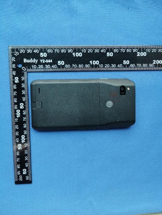
IYG97XX
Oct 06, 2023Wifi/BT Phone
Equipment Class
6XD - 15E 6 GHz Low Power Indoor Client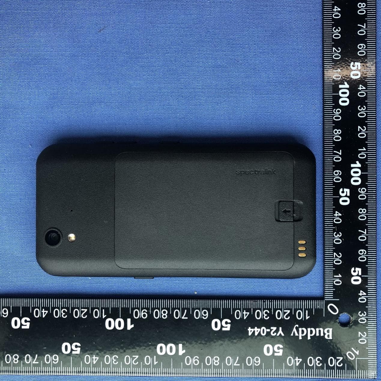
IYG9240
Nov 09, 2020Mobile Phone
Equipment Class
NII - Unlicensed National Information Infrastructure TX
IYG-875X
Feb 04, 2014Wireless IP Phone
Equipment Class
NII - Unlicensed National Information Infrastructure TX
IYGPTB450
Jul 26, 2007Wireless Telephone
Equipment Class
DSS - Part 15 Spread Spectrum Transmitter