J4K-INVITIUMWireless LAN Adapter (unlicensed) PCMCIA
Planar Systems Inc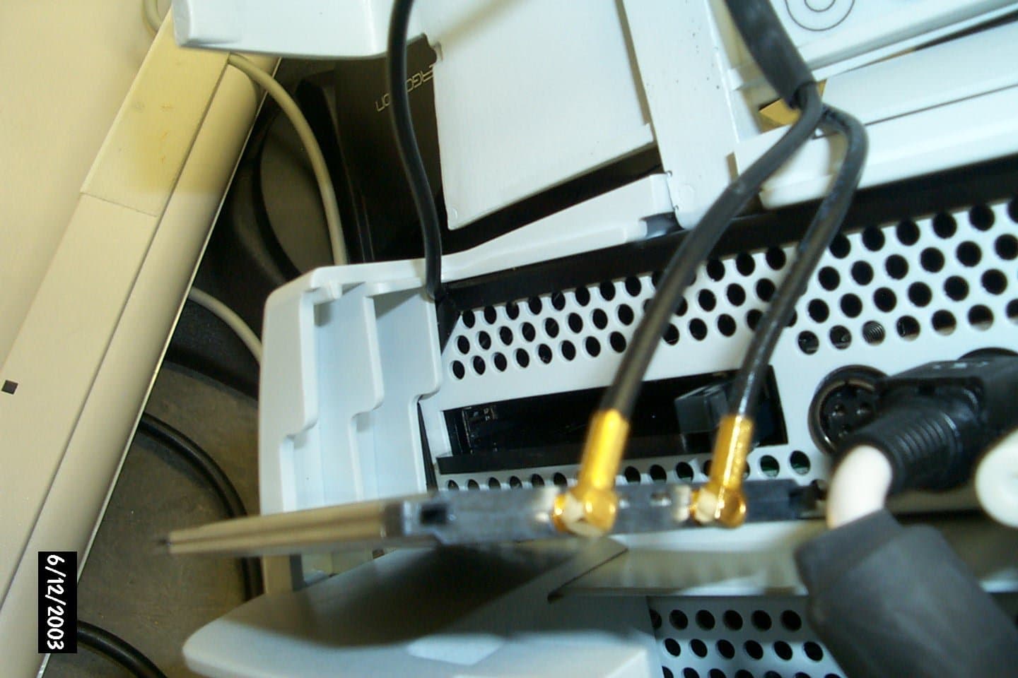
Click to zoom
Application Details
- Equipment Class
- DTS - Digital Transmission System
- Date of Grant
- Aug 04, 2003
- Application Purpose
- Original Equipment
- Date of Application
- Jun 10, 2003
- Equipment Note
- Wireless LAN Adapter (unlicensed) PCMCIA
- Frequency Range
- 2412.00000000 - 2465.00000000
- Company
- Planar Systems Inc
- Country
- United States
Documents & Files
Document Text
Text extracted from the exhibit documents filed with the FCC. Open a document above to read the original.
Users Manual
Planar ® Invitium ™ Medical Workstation Tk7 and Tn4 Operations Manual Planar Systems, Inc. Copyright © 2003, Planar Systems, Inc. All rights reserved. Corporate Headquarters Planar Systems, Inc. 1195 N.W. Compton Drive Beaverton, OR 97006-1992 USA Phone: +1 (503) 748-1100 Fax: +1 (503) 748-1493 Americas Medical Sales Planar Systems, Inc. 400 Fifth Avenue Waltham, MA 02451-8738 USA Phone: +1 (781) 895-1155 Fax: +1 (781) 895-1133 Europe, Middle East, and Africa Medical Sales Planar Systems N.V. Leuvensesteenweg 122c B-3191 Hever, Belgium Phone: +32-15-500-190 Fax: +32-15-500-199 E-mail:[email protected] [email protected] URL:www.planar.com Part Number: 020-0275-00A The information in this document is subject to change without notice. Do not reproduce, transmit, or store this document in a retrieval system without prior written permission of Planar Systems, Inc. Planar is a registered trademark and Invitium is a trademark of Planar Systems, Inc. IBM is a registered trademark and PS/2 is a trademark of International Business Machines Corporation. Microsoft and Windows are registered trademarks of Microsoft Corporation. All other trademarks and trade names are the property of their respective companies. iii Contents Chapter 1 Overview................................................................................... 1 Standard Equipment................................................................................................................1 Optional Equipment.................................................................................................................2 Workstation Configuration.....................................................................................................3 Central processing unit (CPU)............................................................................................3 Supported Mounting Solutions..............................................................................................4 Chapter 2 Installing the Invitium............................................................ 5 Guidelines...................................................................................................................................5 Operating................................................................................................................................5 Mounting................................................................................................................................5 Precautions.................................................................................................................................6 Attach the Mounting Fixture..................................................................................................7 Open the Clamshell..................................................................................................................9 Connect the Cables.................................................................................................................10 Start the Invitium....................................................................................................................12 Adjust the display...............................................................................................................13 Install Additional Software...................................................................................................14 Tn4.........................................................................................................................................14 Tk7.........................................................................................................................................14 Chapter 3 Troubleshooting....................................................................15 Invitium does not start...........................................................................................................15 Invitium freezes or displays an error message..................................................................15 Problem Solving Tips.............................................................................................................16 Index..........................................................................................................17 v U.S. Federal Communications Commission (FCC) Requirements This device was tested and complies with the limits for a Class B digital device, pursuant to Part 15 of the FCC Rules. These limits are designed to provide reasonable protection against harmful interference in a residential installation. This equipment generates, uses, and can radiate radio frequency energy and, if not installed and used in accordance with the instructions, may cause harmful interference to radio communications. There is no guarantee that interference will not occur in a particular installation. If this equipment does cause harmful interference to radio or television reception, which can be determined by turning the equipment off and on, the user is encouraged to try to correct the interference by one or more of the following measures: • Reorient or relocate the receiving antenna. • Increase the separation between the equipment and the receiver. • Connect the equipment to an outlet on a circuit different from that to which the receiver is connected. • Consult the dealer or an experienced radio/TV technician for help. Changes or modifications to this equipment not expressly approved by the party responsible for compliance could void the user’s authority to operate the equipment To comply with the limits for an FCC Class B computing device, always use the shielded signal cord supplied with this unit. The FCC warns that changes or modification of the unit not expressly approved by the party responsible for compliance could void the user’s authority to operate the equipment. Canadian Documentation Notice - Class B Computing Devices This digital apparatus does not exceed the Class B li…
Text truncated - open the document above for the full version.
Cover Letter(s)
Chomerics Test Services 77 Dragon Court Woburn, Massachusetts 01888-4104 781-939-4158 TO: FCC FROM: Patty Terilli Test Services Coordinator RE: FCC ID: J4K-INVITIUM (EA253930) The enclosed package is being submitted to the FCC to certify the Planar Dome Invitium which consists of a CISCO PCMCIA Series 350 and a Planar Dome custom antenna. The PCMCIA card has been previously certified by the FCC under identifier LDK102040 for CISCO/Aironet. This wireless LAN will be used with the Planar Dome Invitium System with Touchscreen PC. The Invitium System is a diagnostic station which will be used in the medical market. The system has been tested and found to comply with the FCC Part 15 Class B requirements under the FCC Declaration of Conformity requirements. The PCMCIA card and associated antenna(s) are housed within the Invitium Monitor and are not user accessible.
Cover Letter(s)
Cisco Systems, Inc. 320 Springside Drive Akron, Ohio 44333 Phone: 330 664-7900 Fax: 330-664-7922 http://www.cisco.com Phone: (330) 664-7362 Fax: (330) 664-7301 E-Mail: [email protected] June 12, 2003 Federal Communications Commission Equipment Authorization Division, Application Processing Branch 7435 Oakland Mills Road Columbia, MD 21046 Re: FCC ID: J4K-Invitium To Whom It May Concern: The following information is to be held confidential pursuant to 47 CFR Part 0 §0.457 and Section 552(b)(4) of the Freedom of Information Act, because the information provided is proprietary and contains trade secrets. If made public, the information might be used to the disadvantage of the Cisco Systems, Inc. in the market place. In addition, this information is to be withheld from the applicant, Planar Dome, as well. Block Diagram Schematic Diagrams Technical Description Best Regards, Jim Nicholson EMC Compliance Engineer
Internal Photos
AIR-LMC/PCM350 AIR-LMC/PCM350
Internal Photos
AIR-LMC/PCM350 AIR-LMC/PCM350
RF Exposure Info
Exhibit #10 RF Exposure. The Planar Dome Invitium, which consists of a CISCO PCMCIA Series 350 and Planar Dome custom antennas A and B. The PCMCIA card and associated antenna(s) are housed within the Invitium Monitor and are not user accessible. The PCMCIA card has been previously certified by the FCC under identifier LDK102040 for CISCO/Aironet. The output power for the CISCO/Aironet PCMCIA Series 350 card is 100mW. The maximum permissible RF exposure for an external uncontrolled environment is 1mW/cm 2 . The electric field generated by the Planar Dome Invitium with the Series 350 was measured at a 20cm distance. A field strength probe was held at a 20cm distance with the Planar Dome Invitium operating at full power. The probe was moved around the Invitium and rotated on its axis to find the maximum field strength. The field strength was measured with a Narda 8616 Electro Radiation Meter and 8621D probe. The maximum field strength measure at 20cm was 0.09w/cm 2 . Notice in Installation Manual: While installing and operating this transmitter and antenna combination the radio frequency exposure limit of 1mW/cm2 may be exceeded at distance close to the antennas installed. Therefore, the user must maintain a minimum distance of 20cm from the antenna at all times.
Test Report
TEST SERVICES EMC EVALUATION OF THE PLANAR DOME INVITIUM IN ACCORDANCE WITH THE FCC PART 15.247 Prepared For: PLANAR DOME 400 FIFTH AVENUE WALTHAM, MASSACHUSETTS 02154 ATTENTION: MEHER NERKIZIAN Prepared By: ROBERT FOSTER CHOMERICS TEST SERVICES 77 DRAGON COURT WOBURN, MASSACHUSETTS 01888 Date: JUNE 4, 2003 Test Report Number: TR3602A.03 Test Technician or Engineer: ___________________________ CTS Approved Signatory: ___________________________ This report shall not be reproduced except in full without the written approval of Chomerics Test Services. TEST SERVICES Planar Dome Invitium Document #: TR3602A.03 Date: June 4, 2003 TABLE OF CONTENTS 1.0 General 1.1 Introduction 1.1.1 Purpose 1.1.2 Requirements 1.2 Test Summary 1.2.1 Summary of Recommendations 1.3 Administrative Data 1.3.1 Test Facility 1.3.2 Equipment Calibration 1.3.3 Test Personnel 1.4 Test Set-up 1.4.1 Test Site Matrix 1.4.2 Test Site Descriptions 1.4.3 Equipment Under Test 2.0 Tests Performed 2.1 Part 15 Subpart C 15.247 Bandwidth 2.1.1 Equipment Used 2.1.2 Test Conditions 2.1.3 Test Method 2.1.4 Results 2.1.5 Test Data 2.1.6 Photographic Documentation 2.2 Part 15 Subpart C 15.247 Power Output 2.2.1 Equipment Used 2.2.2 Test Conditions 2.2.3 Test Method 2.2.4 Results 2.2.5 Test Data 2.2.6 Photographic Documentation 2.3 Part 15 Subpart C 15.247 Field Strength of Fundamental 2.3.1 Equipment Used 2.3.2 Test Conditions 2.3.3 Test Method 2.3.4 Result 2.3.5 Test Data 2.3.6 Photographic Documentation Page 2 of 50 TEST SERVICES Planar Dome Invitium Document #: TR3602A.03 Date: June 4, 2003 2.4 Part 15 Subpart C 15.247 Spurious Emissions 2.4.1 Equipment Used 2.4.2 Test Conditions 2.4.3 Test Method 2.4.4 Results 2.4.5 Test Data 2.4.6 Photographic Documentation 2.5 Part 15 Subpart C 15.247 Band Edge 2.5.1 Equipment Used 2.5.2 Test Conditions 2.5.3 Test Method 2.5.4 Results 2.5.5 Test Data 2.5.6 Photographic Documentation 2.6 Part 15 Subpart C 15.247 Power Spectral Density 2.6.1 Equipment Used 2.6.2 Test Conditions 2.6.3 Test Method 2.6.4 Results 2.6.5 Test Data 2.6.6 Photographic Documentation 2.7 Part 15 Subpart C 15.247 Field Strength Harmonics 2.7.1 Equipment Used 2.7.2 Test Conditions 2.7.3 Test Method 2.7.4 Results 2.7.5 Test Data 2.7.6 Photographic Documentation Appendix A: Test Log Appendix B: Photographs of Antenna Page 3 of 50 TEST SERVICES Planar Dome Invitium Document #: TR3602A.03 Date: June 4, 2003 LIST OF DEFINITIONS/ABBREVIATIONS AC Alternating Current BB Broadband BW Bandwidth cm Centimeter C.P.U. Calibrate Prior to Use dB Decibel DC Direct Current EMC Electromagnetic Compatibility EMI Electromagnetic Interference ER Electric Radiation EUT Equipment Under Test GHz GigaHertz Hz Hertz I-face Interface kHz KiloHertz m Meter MHz MegaHertz mm Millimeter mS Millisecond mV MilliVolt MR Magnetic Radiation NB Narrowband N.C.R. No Calibration Required PLC Power Line Conduction PPS Pulses Per Second uF MicroFarad uH MicroHenry uS Microsecond uV MicroVolt U.W.C. Use With Calibrated Equipment Page 4 of 50 TEST SERVICES Planar Dome Invitium Document #: TR3602A.03 Date: June 4, 2003 1.0 GENERAL 1.1 Introduction 1.1.1 Purpose The purpose of this report is to document the performance of the Planar Dome Invitium during a variety of radio-performance tests and record the test requirements and procedures used. At the request of Planar Dome, the tests were performed by Chomerics Test Service (CTS) of Woburn, Massachusetts. The assessment will determine the compliance or non-compliance to the requirements set by FCC Part 15 Subpart B and C. Testing was performed during the period of May 22 through May 28, 2003 under Chomerics order number 896015. 1.1.2 Requirements The requirements for the sequence of tests performed on the Planar Dome Invitium are as follows: FCC Part 15 Subpart C 15.247 Bandwidth For Direct Sequence systems, the minimum 6dB bandwidth shall be at least 500kHz. FCC Part 15 Subpart C 15.247 Output Power For Direct Sequence systems, the maximum output power is 1 Watt. FCC Part 15 Subpart C 15.247 Spurious In any 100kHz bandwidth outside the frequency band in which the spread spectrum intentional radiator is operating, the radio frequency power that is produced by the intentional radiator shall be at least 20dB below that in the 100kHz bandwidth within the band that contains the highest level of the desired power, based on either an RF conducted or a radiated measurement. FCC Part 15 Subpart C 15.247 Power Spectral Density For direct sequence systems, the peak power spectral density conducted from the intentional radiator to the antenna shall not be greater than 8dBm in any 3kHz band during any interval of continuous transmission. Page 5 of 50 TEST SERVICES Planar Dome Invitium Document #: TR3602A.03 Date: June 4, 2003 FCC Part 15 Subpart C 15.249 Field strength of the Fundamental and Harmonics Field Strength of Fundamental and Harmonics Frequency (MHz) Fundamental (mV/meter) Harmonics (uV/meter) 2400-2483.5 50 500 FCC Part 15 Subpart C Band-Edge In any 100kHz bandwidth outside the frequency band in which the spread spectrum intentional radiator is operating, the radio frequency power that is produced by the intentional radiator shall be at least 20dB below that in the 100kHz bandwidth within the band that contains the highest level of desired power, based on either an RF conducted or a radiated measurement. 1.2 Summary The terms "Passed" or "Failed" in this section are intended to guide the reader as to whether or not the EUT met the minimum Performance Criteria that can be interpreted from the FCC Parts 2, 15. The "Results" paragraph in each test section to follow, and the test data sheets, will outline specifically how the EUT performed during each test. Bandwidth Passed Power Output Passed Field Strength Fundamental Passed Spurious Emission Passed Band Edge Passed Power Spectral Density Passed Field Strength Harmonics & Spurious Passed 1.2.1 Summary of Recommendations The Planar Dome Invitium will not require modification…
Text truncated - open the document above for the full version.
Test Setup Photos
TEST SETUP PHOTOGRAPHS Photographic Documentation CUSTOMER: PLANAR DOME DATE: MAY 28, 2003 E QUIPMENT: INVITIUM TEST NUMBER: 1 T ESTED BY: ROBERT FOSTER COUPLING DEVICE: O PERATING MODE: CONTINUOUS TRANSMISSION TEST SPEC: Photograph Description: FORM CTS-PHOTO Planar Dome Invitium Document #: TR3602A.03 Date: June 4, 2003 Page 1 of 7 2.2.6 Photographic Documentation CUSTOMER: PLANAR DOME DATE: MAY 28, 2003 E QUIPMENT: INVITIUM TEST NUMBER: 2 TESTED BY: ROBERT FOSTER COUPLING DEVICE: O PERATING MODE: CONTINUOUS TRANSMISSION TEST SPEC: Photograph Description: FORM CTS-PHOTO Planar Dome Invitium Document #: TR3602A.03 Date: June 4, 2003 Page 2 of 7 2.3.6 Photographic Documentation CUSTOMER: PLANAR DOME DATE: MAY 28, 2003 EQUIPMENT: INVITIUM TEST NUMBER: 3 T ESTED BY: ROBERT FOSTER COUPLING DEVICE: O PERATING MODE: CONTINUOUS TRANSMISSION TEST SPEC: Photograph Description: FORM CTS-PHOTO Planar Dome Invitium Document #: TR3602A.03 Date: June 4, 2003 Page 3 of 7 2.4.6 Photographic Documentation CUSTOMER: PLANAR DOME DATE: MAY 22, 2003 E QUIPMENT: INVITIUM TEST NUMBER: 4 T ESTED BY: ROBERT FOSTER COUPLING DEVICE: O PERATING MODE: CONTINUOUS TRANSMISSION TEST SPEC: Photograph Description: FORM CTS-PHOTO Planar Dome Invitium Document #: TR3602A.03 Date: June 4, 2003 Page 4 of 7 2.5.6 Photographic Documentation CUSTOMER: PLANAR DOME DATE: MAY 28, 2003 E QUIPMENT: INVITIUM TEST NUMBER: 5 T ESTED BY: ROBERT FOSTER COUPLING DEVICE: OPERATING MODE: CONTINUOUS TRANSMISSION TEST SPEC: Photograph Description: FORM CTS-PHOTO Planar Dome Invitium Document #: TR3602A.03 Date: June 4, 2003 Page 5 of 7 2.6.6 Photographic Documentation CUSTOMER: PLANAR DOME DATE: MAY 28, 2003 E QUIPMENT: INVITIUM TEST NUMBER: 6 TESTED BY: ROBERT FOSTER COUPLING DEVICE: O PERATING MODE: CONTINUOUS TRANSMISSION TEST SPEC: Photograph Description: FORM CTS-PHOTO Planar Dome Invitium Document #: TR3602A.03 Date: June 4, 2003 Page 6 of 7 2.7.6 Photographic Documentation CUSTOMER: PLANAR DOME DATE: MAY 22, 2003 E QUIPMENT: INVITIUM TEST NUMBER: 7 TESTED BY: ROBERT FOSTER COUPLING DEVICE: O PERATING MODE: CONTINUOUS TRANSMISSION TEST SPEC: Photograph Description: FORM CTS-PHOTO Planar Dome Invitium Document #: TR3602A.03 Date: June 4, 2003 Page 7 of 7
Contact Information
Applicant
Brian Harlan(Director of Regulatory Compliance)
Technical Contact
Chomerics Test ServicesPatricia L Terilli
[email protected]781-939-4158
77 Dragon Court · Woburn, Massachusetts · United States
Non-Technical Contact
Chomerics Test ServicesPatricia L Terilli
[email protected]781-939-4158
Test Firm
Chomerics Test ServicesDavid Inman
Technical Specifications
| # | Rule Parts | Frequency Range | Power Output |
|---|---|---|---|
| 1 | 15C | 2.41 GHz - 2.46 GHz | 100.00 mW |
Other Applications from Planar Systems Inc
J4KELT1
Aug 27, 1992Flat Screen Computer Terminal
Equipment Class
JBP - Part 15 Class B Computing Device Peripheral