JFVKYRF-LDK-1TuneView iPod Dock
InnoSys Incorporated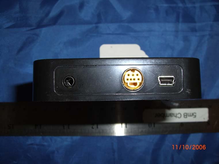
Click to zoom
Application Details
- Equipment Class
- DSS - Part 15 Spread Spectrum Transmitter
- Date of Grant
- Dec 12, 2006
- Application Purpose
- Original Equipment
- Date of Application
- Dec 12, 2006
- Equipment Note
- TuneView iPod Dock
- Frequency Range
- 2402.00000000 - 2479.00000000
- Company
- InnoSys Incorporated
- Country
- United States
Documents & Files
Document Text
Text extracted from the exhibit documents filed with the FCC. Open a document above to read the original.
Users Manual
..................................................Introduction 2 • Package Contents (TVI-200C) • Requirements ............Setting Up Your TuneView for iPod 3 • Connecting Everything Together .....................Using The TuneView Remote 7 • Using The TuneView Remote • Setup Menu • Language Settings • Repeat Settings • Scroll Thumb Settings • Firmware • The Wizard Button ...........................................Troubleshooting 10 • Sync Your Remote To Your Dock • Reset To Factory Settings • Menu Navigation Is Sluggish / Range Issues • No Audio • Error Message - iPod Busy • Error Message - iPod Not Connected • Message - Starting Player ....................................Support Information 12 • Support Options (US Based) • International Support Options ..........................Specs - TuneView for iPod 13 • Package Contents (TVI-200C) • Buttons On Remote • Other Details .....................Warranty Information [1 Year] 14 • Definitions • Limited Warranty on Hardware: • How To Obtain Warranty Service/Repair .........................................................Notices 16 • United States FCC • CE MARK DECLARATION OF CONFORMITY • Canada Digital Apparatus EMI Standard • Australia/New Zealand • Copyright • Trademarks TuneView for iPod - User Manual (rev 11/22/06) Page 1 of 18 TuneView for iPod USER MANUAL for p/n TVI-200C Introduction TuneView for iPod provides a new wireless way to manage your music throughout your house or office. TuneView allows you to: * Connect the iPod to a stereo or powered speakers using the line out jack * Connect the iPod to a TV using the S-Video jack * Charge the iPod from an AC outlet using the USB Power Adapter * Browse and control the iPod from around the house with LCD remote. The TuneView dock may also be used to sync an iPod with a PC or Mac. Both the TuneView dock and TuneView remote are USB devices that can be updated via a firm- ware download (just like an iPod). Over time we will release firmware updates that add new ca- pabilities to TuneView. Package Contents (TVI-200C) The Keyspan TuneView for iPod package (TVI-200C Package) contains the following items: • TuneView Dock • Dock Adapters: • TuneView Remote iPod mini • USB Power Adapter iPod (20GB, U2) • USB Cable iPod with color display (20GB, 30GB, U2) • Audio Cable • Batteries: (3.5mm stereo to dual RCA) Two AA Batteries Requirements iPod mini with firmware v1.4.1 or greater 4G Pod (BW Display) 4th generation with firmware v3.1.1 or greater iPod Photo (aka iPod with Color Display) 4th generation with firmware v1.2.1 or greater nano 1st generation with firmware v1.2.0 or greater 5G Pod 5th generation (video) with firmware v1.2.0 or greater 2G nano 2nd generation (aluminum) with firmware v1.0.1 or greater TuneView for iPod - User Manual (rev 11/22/06) Page 2 of 18 Setting Up Your TuneView for iPod Connecting Everything Together Step 1 - Connect The Audio and Video Cables To Your Dock Audio: Connect the audio cable's 3.5mm stereo jack to the LINE OUT port on the back of the TuneView Dock. Next, connect the stereo cable's dual RCA connectors to your stereo/speakers. Video: S-Video jack allows connection to a TV for viewing slideshows and video (if your iPod supports these features). Connect one end of an S-Video cable (not included in the TVI-200C Package) to the S-VIDEO OUT port on the TuneView Dock and then connect the other end into your TV. Step 2 - Connect The USB Cable/Power Supply To Your Dock Power Via Included USB Power Adapter: Connect one end of the USB cable to the SYNC/POWER port on the TuneView Dock. Connect the other end of the USB ca- ble to the USB port on the USB Power Adapter. Power Via Your Computer's USB Port: You can also use your computer's USB port to power your dock as well as to sync your iPod to your computer. To do this, con- nect the one end of the USB cable to the SYNC/POWER port on your do. Connect the other end of the USB cable to the USB port on your computer. Troubleshooting Tip: When you turn on your TuneView Dock, it's status light will turn on and then turn off indicating that the dock is working and read to use. TuneView for iPod - User Manual (rev 11/22/06) Page 3 of 18 Step 3 - Insert Included Batteries Into The TuneView Remote Turn over your TuneView Remote and remove the bat- tery cover. Then insert the the two AA batteries and re- place the battery cover. The TuneView LCD screen will now turn on. Your remote establish communication with the dock. For now, the LCD screen should display the message 'iPod Not Connected'. If you see this message, Proceed to the next step. If You Have Multiple TuneView Remotes/Docks: The TuneView dock will automatically sync (aka pair) with to the first TuneView remote it detects. If you have multiple sets of TuneView docks and remotes, please turn them on one at a time so that they can properly commu- nicate with during setup. After setup, they will can all be turned on at the same time and functioning at the same time. Step 4 - Insert Universal Dock Adapter and iPod Into The TuneView Dock TuneView for iPod - User Manual (rev 11/22/06) Page 4 of 18
Users Manual
Insert Universal Dock Adapters: Insert the appropriate Universal Dock Adapter for your iPod. The TuneView Dock includes three dock adapters for use with iPod : #3 - iPod mini (4GB or 6GB), #4 - 4G iPod (20GB or U2 Special Ed.), #6 - iPod with color display (20GB, 30GB, or U2 Special Ed.). If you have a 4G iPod (40GB) or an iPod with color display (40GB or 60GB), please purchase the appropriate dock adapter from Apple. If you have a newer iPod (such as a nano 1G, nano 2G, or 5G iPod with video), please use the dock insert that came with your iPod. Once the dock adapter is installed, connect your iPod to the TuneView Dock. Step 5 - Check For Communication / Finishing Up At this point, you will see the Keyspan logo on you iPod's screen, your iPod is now charging and is ready to be used with the TuneView. Pro- ceed to to the Step 6. Troubleshooting Tip: If you do not see the Keyspan logo on your iPod's screen, try discon- necting and reconnecting the iPod from the dock. You can also try re- moving the universal dock adapter and then connecting the iPod. TuneView Dock Powered Via Your Computer's USB Port: If you connected the TuneView Dock to your computer's USB port, your iPod will now sync and charge (ask indicated by the standard DO NOT DISCONNECT message on your iPod's screen). If you want to use the TuneView Remote to control your iPod, unmount/eject from your com- puter. This will give control of the iPod back to the TuneView dock. When you see the Keyspan logo appear on your iPod screen, proceed to to the Step 6. Step 6 - Finishing Up TuneView for iPod - User Manual (rev 11/22/06) Page 5 of 18 The TuneView LCD screen will now display the TuneView's Main Menu screen (see image). Your TuneView for iPod is ready for use! You can now use the remote to browse your iPod contents. For more details on how to use the the remote and information about its buttons, proceed to the next section, Using Your TuneView Remote. Troubleshooting Tip: If your TuneView Remote reports iPod Not Connected, try discon- necting and reconnecting the iPod from the dock. You can also try removing the universal dock adapter and then connecting the iPod. If the remote reports iPod Busy, your iPod is being con- trolled by another source (ie your computer). If you connected to the TuneView dock to your computer, make sure that you have ejected/unmounted the iPod from your computer. See the Troubleshooting section for more details and instructions. Language Settings: The TuneView Remote menu system can be displayed in English (default setting), Spanish, French, and German. This is set in the Setup screen under the the TuneView's Main Menu (navigate to Main Menu > Setup > ). TuneView for iPod - User Manual (rev 11/22/06) Page 6 of 18
Users Manual
Using The TuneView Remote Once the Keyspan TuneView remote and dock are communicating with each other, you will be able to see the TuneView Main Menu. The Main Menu contains the following static menus: • Playlists • Artists • Albums • Genres • Songs • Composers • Audiobooks • Podcasts • Setup Note: You will see all of these menus regardless whether your iPod contains certain categories. The Main Menu is static an does not change whereas subsequent menus and screens are dy- namic. Using The TuneView Remote The Keyspan TuneView for iPod includes an unique 9-Way button and a Wizard button. Wizard Button Volume Down Volume Up Next Track Press and Hold for [Fast Forward] Previous Track Press and Hold for [Rewind] Play / Pause (Previous) Menu Select Up Arrow (navigation) Down Arrow (navigation) TuneView for iPod - User Manual (rev 11/22/06) Page 7 of 18 You will use these buttons to navigate the TuneView interface. Up / Down Arrows Use to scroll up/down menus Select Use to select a choice Play/Pause Use to play/pause current file Menu Use to return to previous menu Volume Up / Down Use to change volume Next Track [Fast Forward] Press once to go to next track/chapter Press and Hold to fast forward Previous Track [Rewind] Press once to go to previous track/chapter Press and Hold to rewind Wizard button The Wizard button will display a dynamic menu based on what you are currently doing. While browsing songs, the Wizard button will let you jump to the beginning, middle, or end of a list. For details about the Wizard button, see the Wizard button information later in this section. Setup Menu The Setup Menu (located in Main Menu > Setup) allows contains the following settings. • English (Default) • Spanish • French • German • Shuffle Tracks/Albums/Off • Repeat Tracks/All Tracks/Off • Scroll Thumb Off/On (Default is On) • Firmware Language Settings The TuneView Remote menu system can be displayed in English (default setting), Spanish, French, and German. You change this by selecting your desired language within the Setup menu (navigate to Main Menu > Setup > ). The factory setting is English. Shuffle Settings You can set your shuffle settings to OFF/Tracks/Album. This change is made on your iPod and will remain after remove your iPod from your dock. You can then change your iPod's shuffle setting via your iPod's Settings menu (Main Menu > Settings > Shuffle). Repeat Settings TuneView for iPod - User Manual (rev 11/22/06) Page 8 of 18 You can set your repeat settings to OFF/Tracks/All Tracks. This change is made on your iPod and will remain after remove your iPod from your dock. You can then change your iPod's repeat setting via your iPod's Repeat menu (Main Menu > Settings > Repeat). Scroll Thumb Settings By default, the TuneView display a Scroll Thumb to the right of the TuneView screen to indicate position within a list. You can turn off the scroll thumb via the Setup menu (navigate to Main Menu > Setup > ). The factory setting is On. Firmware You can view your TuneView Remote and TuneView Dock firmware by accessing the Firmware command (navigate to Main Menu > Setup > Firmware). Please note that the remote and dock each have their own firmware. As Apple releases new iPods, Keyspan may update the TuneView firmware to take advantage of new feature or to fix bugs. Infor- mation about firmware updates will be posed on Keyspan's website. The Wizard Button The yellow dog jumped over the gray fox. The yellow dog jumped over the gray fox. The yellow dog jumped over the gray fox. The yellow dog jumped over the gray fox. • Go To Start • Go To Middle • Go To End • Mute ON/OFF • Mode: TuneView / iPod • Sleep About TuneView / iPod Modes By default, your TuneView is set to TuneView mode. In this mode, the TuneView product con- trols your iPod via the Dock Connector. All information is sent to the TuneView remote which retains exclusive control of your iPod. In this mode, the iPod's controls (ie click wheel) are not available. You can switch the control mode to iPod mode. In iPod mode, your remote will con- trol your iPod but your iPod will not send any information to the TuneView remote's screen. When iPod mode is turned on, your TuneView remote will display the iPod controls enabled. TuneView operating in Simple Remote Mode message. When in iPod mode, you can switch back to TuneView mode by hitting the Wizard button and changing the Mode setting. TuneView for iPod - User Manual (rev 11/22/06) Page 9 of 18 Troubleshooting If you are having problems with your TuneView Remote, this section provides troubleshooting information that will assist you in troubleshooting your TuneView for iPod. Sync Your Remote To Your Dock Reset To Factory Settings If you are having communications issues, issues with other TuneView products, or if you need to reset to factory settings, please do the following: Step 1: On the TuneView Remote, press and hold the Wizard button and the Up Arrow button at the same time. This is will reset your remote and an animated red lighting bolt will appear on the remote's screen. Step 2: On the TuneView Dock, locate the Pair With Remote button on the bottom of the dock. Press this button with a paper clip (or similar object). This will cause the dock's Status light to blink rapidly. At this point, your dock is read to pair/sync with the first remote it detects. Step 3: On the TuneView Remote, press any button. The animated red lighting bolt will disappear when communication has been estab- lished with the dock. If your have any problems with this process, contact Keyspan support. Menu Navigation Is Sluggish / Range Issues The TuneView for iPod has a range of 150 feet in open space. This distance may be reduce by the remote and dock's signal traveling through walls and other solid objects. As you get to the limits of your remote control's range, your remote control navigation performance may appear to be sluggish or sporadic. If this happens, move close to the TuneView dock. No Audio If you do not hea…
Text truncated - open the document above for the full version.
Cover Letter(s)
InnoSys 4118 Lakeside Drive Richmond, CA 94806 (510) 222-7717 (510) 222-0323 Fax Federal Communications Commission Authorization and Evaluation Division Confidentiality Request regarding application for certification of FCC ID: JFVKYRF-LDK-1 Pursuant to Sections 0.457 and 0.459 of the Commission’s Rules, we hereby request confidential treatment of information accompanying this application as outlined below: - Technical Specification and description - Schematics - Block Diagram - Theory of Operation The above materials contain trade secrets and proprietary information not customarily released to the public. The public disclosure of these materials may be harmful to the applicant and provide unjustified benefits to its competitors. The applicant understands that pursuant to Section 0.457 of the Rules, disclosure of this application and all accompanying documentation will not be made before the date of the Grant for this application. Sincerely, Eric Welch Vice President and CTO 11/9/06
Cover Letter(s)
Bay Area Compliance Laboratories Corp. 1274 Anvilwood Avenue Sunnyvale, CA 94089 Phone: (408)-732-9162 Fax: (408)-732-9164 2007-05-11 Federal Communications Commission (FCC) 445 12th Street, SW Washington, DC 20554 Dear Sir or Madam: Acting on behalf of Innosys Inc. (Keyspan) and their product Bay Area Compliance Laboratories has made all necessary revisions to Innosys submission: FCC ID JFVKYRF-LDK-1 / TC543789. We have uploaded new Test Report exhibit (Revised Test Report) with revised frequency range information. The original submission listed the incorrect frequency range of 2402 – 2483 MHz; the correct frequency range of the device is 2402 – 2479 MHz. Any and all other information relating to this change has also been revised appropriately. Please supersede the original test report exhibit with the revised test report exhibit. If there are any other questions or concerns in this matter please feel free to contact us at [email protected] , have a great day! Douglas Mendez Document Control Supervisor Bay Area Compliance Laboratories Corp.
External Photos
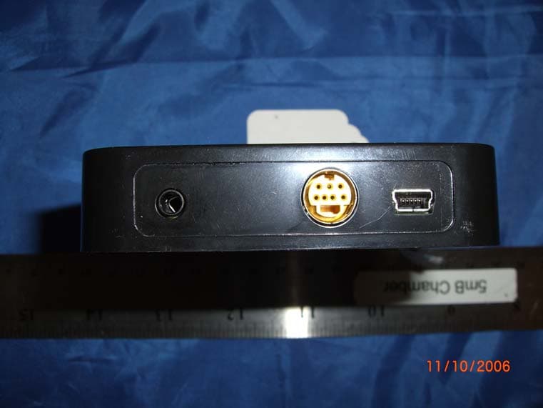
InnoSys (KeySpan) FCC ID: JFVKYRF-LDK-1 Report # R0611022-247 Page 52 of 56 FCC Part 15.247 Test Report EXHIBIT C - EUT PHOTOGRAPHS EUT – Exterior: Top View EUT – Exterior: Bottom View InnoSys (KeySpan) FCC ID: JFVKYRF-LDK-1 Report # R0611022-247 Page 53 of 56 FCC Part 15.247 Test Report EUT – Exterior: Side View 1 EUT – Exterior: Side View 2 InnoSys (KeySpan) FCC ID: JFVKYRF-LDK-1 Report # R0611022-247 Page 54 of 56 FCC Part 15.247 Test Report EUT – Exterior: Side View 3 EUT – Exterior: Port View
ID Label/Location Info
InnoSys (KeySpan) FCC ID: JFVKYRF-LDK-1 Report # R0611022-247 Page 49 of 56 FCC Part 15.247 Test Report EXHIBIT A – FCC PRODUCT LABELING AND WARNING STATEMENT FCC ID Label The FCC labels should contain FCC statement in FCC 15.19 paragraph (3). A sample of the statement is presented hereinafter as reference. Also, as per FCC §15.19 a(4) Where a device is constructed in two or more sections connected by wires and marketed together, the statement specified above is required to be affixed only to the main control unit. If the EUT is integrated within another device then a label affixed to the host shall also state, “Contains FCC ID: JFVKYRF-LDK-1” Proposed Label Location on EUT Back View of EUT / Proposed FCC ID Location As per FCC §15.19 (b)(4), the label shall not be a stick-on, paper label. The label on these products shall be permanently affixed to the product and shall be readily visible to the purchaser at the time of purchase, as described in Section 2.925(d) of this chapter. "Permanently affixed" means that the label is etched, engraved, stamped, silk-screened, indelibly printed, or otherwise permanently marked on a permanently attached part of the equipment or on a nameplate of metal, plastic, or other material fastened to the equipment by welding, riveting, or a permanent adhesive. The label must be designed to last the expected lifetime of the equipment in the environment in which the equipment may be operated and must not be readily detachable. FCC ID: JFVKYRF-LDK-1 This device complies with Part 15 of the FCC Rules. Operation is subject to the following two conditions: (1) this device may not cause harmful interference, and (2) this device must accept any interference received, including interference that may cause undesired operation. 2.1875" 1.0"
Internal Photos
InnoSys (KeySpan) FCC ID: JFVKYRF-LDK-1 Report # R0611022-247 Page 55 of 56 FCC Part 15.247 Test Report EUT – Interior: PCB: Top Side View EUT – Interior: PCB Top Side View (Antenna Detail) InnoSys (KeySpan) FCC ID: JFVKYRF-LDK-1 Report # R0611022-247 Page 56 of 56 FCC Part 15.247 Test Report EUT – Interior: PCB Bottom Side View EUT – Interior: PCB Bottom Side View (RF Shielding Removed) END REPORT
RF Exposure Info
InnoSys (KeySpan) FCC ID: JFVKYRF-LDK-1 Report # R0611022-247 Page 48 of 56 FCC Part 15.247 Test Report § 15.247 (e) (i) and § 2.1091 - RF EXPOSURE According to §15.247(e)(i) and §1.1307(b)(1), systems operating under the provisions of this section shall be operated in a manner that ensures that the public is not exposed to radio frequency energy level in excess of the Commission’s guidelines. According to §1.1310 and §2.1091 RF exposure is calculated. Limits for General Population/Uncontrolled Exposure Limits for General Population/Uncontrolled Exposure Frequency Range (MHz) Electric Field Strength (V/m) Magnetic Field Strength (A/m) Power Density (mW/cm 2 ) Averaging Time (minutes) 0.3-1.34 614 1.63 *(100) 30 1.34-30 824/f 2.19/f *(180/f 2 ) 30 30-300 27.5 0.073 0.2 30 300-1500 / / f/1500 30 1500-100,000 / / 1.0 30 f = frequency in MHz * = Plane-wave equivalent power density MPE Prediction Predication of MPE limit at a given distance Equation from page 18 of OET Bulletin 65, Edition 97-01 S = PG/4πR² Where: S = power density P = power input to antenna G = power gain of the antenna in the direction of interest relative to an isotropic radiator R = distance to the center of radiation of the antenna Maximum peak output power at antenna input terminal: 11.33(dBm ) Maximum peak output power at antenna input terminal: 13.58 (mw) Prediction distance: 20 (cm) Predication frequency: 2442 (MHz) Antenna Gain (typical): 5.0 (dBi) Antenna gain: 3.16 (numeric) Power density at predication frequency at 20 cm: 0.00854(mW/cm 2 ) MPE limit for uncontrolled exposure at prediction frequency: 1.0 (mW/cm 2 ) Test Result The EUT is a mobile device. The power density level at 20 cm is 0.00854mW/cm², which is below the uncontrolled exposure limit of 1.0mW/cm² at 2442 MHz.
Test Report
Note: This test report is for the customer shown above and their specific product only. It may not be duplicated or used in part without prior written consent from Bay Area Compliance Laboratories Corp. This report must not be used by the customer to claim product certification, approval, or endorsement by NVLAP or any agency of the U.S. Government . FCC PART 15.247 MEASUREMENT AND TEST REPORT For InnoSys (KeySpan) 4118 Lakeside Drive Richmond, CA 94806 FCC ID: JFVKYRF-LDK-1 Model: KYRF-LDK This Report Concerns: Original Report (rev.1) Equipment Type: Dock for iPod Test Engineer: James Ma Report Number: R0611022-247a Report Date: 2006-11-27 Reviewed By: Daniel Deng Prepared By: (12) Bay Area Compliance Laboratories Corp. (BACL) 1274 Anvilwood Ave. Sunnyvale, CA 94089, USA Tel: (408) 732-9162 Fax: (408) 732-9164 InnoSys (KeySpan) FCC ID: JFVKYRF-LDK-1 Report #: R0611022-247a Page 2 of 60 FCC Part 15.247 Test Report TABLE OF CONTENTS GENERAL INFORMATION.......................................................................................................................................5 PRODUCT DESCRIPTION FOR EQUIPMENT UNDER TEST (EUT) ....................................................................................5 EUT PHOTO.................................................................................................................................................................5 EUT MECHANICAL DESCRIPTION................................................................................................................................5 OBJECTIVE...................................................................................................................................................................6 RELATED SUBMITTAL(S)/GRANT(S).............................................................................................................................6 TEST METHODOLOGY..................................................................................................................................................6 MEASUREMENT UNCERTAINTY....................................................................................................................................6 TEST FACILITY.............................................................................................................................................................6 SYSTEM TEST CONFIGURATION ..........................................................................................................................7 JUSTIFICATION.............................................................................................................................................................7 SPECIAL ACCESSORIES.................................................................................................................................................7 EQUIPMENT MODIFICATIONS.......................................................................................................................................7 POWER SUPPLY............................................................................................................................................................7 INTERFACE PORTS AND CABLING.................................................................................................................................7 LOCAL SUPPORT EQUIPMENT.......................................................................................................................................7 SUMMARY OF TEST RESULTS FOR FCC PART 15............................................................................................8 §15.203 - ANTENNA REQUIREMENT......................................................................................................................9 APPLICABLE STANDARD..............................................................................................................................................9 ANTENNA CONNECTED CONSTRUCTION......................................................................................................................9 §15.207 – CONDUCTED EMISSIONS .....................................................................................................................10 APPLICABLE STANDARD............................................................................................................................................10 TEST SETUP................................................................................................................................................................10 TEST EQUIPMENT LIST AND DETAILS.........................................................................................................................10 TEST PROCEDURE......................................................................................................................................................10 TEST SETUP DIAGRAM...............................................................................................................................................11 SUMMARY OF TEST RESULTS.....................................................................................................................................11 LINE 1 CONDUCTOR MODE........................................................................................................................................12 QP MEASUREMENTS..................................................................................................................................................12 AVERAGE MEASUREMENTS.......................................................................................................................................12 NEUTRAL LINE CONDUCTOR MODE...........................................................................................................................13 QP MEASUREMENTS...................................................................................................…
Text truncated - open the document above for the full version.
Test Setup Photos
InnoSys (KeySpan) FCC ID: JFVKYRF-LDK-1 Report # R0611022-247 Page 50 of 56 FCC Part 15.247 Test Report EXHIBIT B – TEST SETUP PHOTOGRAPHS Conducted Emissions – Front View Conducted Emissions – Side View InnoSys (KeySpan) FCC ID: JFVKYRF-LDK-1 Report # R0611022-247 Page 51 of 56 FCC Part 15.247 Test Report Radiated Emissions – Front View Radiated Emissions – Rear View
Contact Information
Applicant
David Miller
Test Firm
Bay Area Compliance LaboratoryJohn Chan
Technical Specifications
| # | Rule Parts | Frequency Range | Power Output |
|---|---|---|---|
| 1 | 15C | 2.40 GHz - 2.48 GHz | 13.58 mW |
Other Applications from InnoSys Incorporated
JFVKYRF-RMLN-1
Dec 12, 2006TuneView Remote Control for iPod Dock
Equipment Class
DSS - Part 15 Spread Spectrum TransmitterJFVINSCCQPA
Mar 04, 1996Serial Interface Card w/External Box
Equipment Class
JBP - Part 15 Class B Computing Device PeripheralJFVINSCCSA
Nov 14, 1993SBUS I/O Card
Equipment Class
JBP - Part 15 Class B Computing Device PeripheralJFVINSCCLCA
Oct 02, 1991Serial Communications Card
Equipment Class
JBP - Part 15 Class B Computing Device Peripheral