JFZBP24Studio Broadcast UWB Wireless Microphone System
Audio-Technica Corporation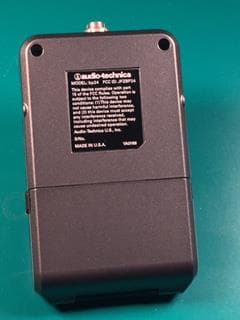
Click to zoom
Application Details
- Equipment Class
- UWB - Ultra Wideband Transmitter
- Date of Grant
- Dec 14, 2015
- Application Purpose
- Original Equipment
- Date of Application
- Dec 14, 2015
- Equipment Note
- Studio Broadcast UWB Wireless Microphone System
- Frequency Range
- 6127.80000000 - 7778.40000000
- Company
- Audio-Technica Corporation
- Country
- Japan
Documents & Files
Document Text
Text extracted from the exhibit documents filed with the FCC. Open a document above to read the original.
Users Manual
Studio Broadcast System SET UP and USE BP24 Bodypack Transmitter Studio Broadcast System Page 2 of 11 1. REGULATORY AND COMPLIANCE STATEMENTS ............................................................................................................ 3 2. BP24 BODYPACK TRANSMITTER ..................................................................................................................................... 3. POSITIONING AND SET UP.............................................................................................................................................................. 4. SYSTEM QUICK START ................................................................................................................................................ Studio Broadcast System Page 3 of 11 1. REGULATORY AND COMPLIANCE Studio Broadcast System Page 4 of 11 2 BP24 UWB Body Pack Transmitter 2.1 Transmitter Controls An On/Off power switch is located in the battery compartment. The adjustable transmitter parameters are: 1. System ID (SYS) – Each transmitter must be assigned a system ID (1-9) that must match the system ID set on the MCU3224 The transmitter will only transmit when it receives a sync pulse and matching system ID from an active system. This will prevent users with transmitters assigned the same channel slot on a different system from interfering if they enter the coverage area. Note: RP timing signals from separate systems must be RF isolated from one another to prevent system timing contention in transmitters. 2. Channel Number (CHAN) – The channel slot assigned to the transmitter (01- 24.) Each transmitter in the system is assigned a unique channel number. 3. Input level (GAIN) – Adjustment of the audio input level (0 dB to 20dB in 2dB Steps). The adjustable transmitter parameters are shown on a display located on the face of the transmitter. The display will only be illuminated when the user is adjusting the transmitter. Pressing any button will activate the display for 10 seconds. After 10 seconds, display functions will no longer be illuminated although the BP is functioning. Pressing any button will light the display in order to check for power or operating condition. Studio Broadcast System Page 5 of 11 Adjustment Process: 1. Press and Hold (2 sec) the button associated with the parameter to be adjusted - SYS, CHAN or GAIN. 2. The selected parameter value will flash on the screen. 3. Make the adjustment via the up down arrow keys. 4. The new value will be shown 5. Confirm the change by pressing the same parameter button as step 1. 6. The changed value will flash twice indicating the parameter change. Note: If there is no button pressed for a 10 second period the transmitter will revert to its original settings and the display will go dark. Note: No parameter changes will be made unless confirmed as indicated in step 5 above. Pressing a different parameter selection button, or allowing a 10 second period without any input abandons any change in process. Note: GAIN value is automatically sent to and adjusted at the MCU3224 display. BP GAIN setting may also be changed via MCU3224 transmitter detail screen System ID Channel SYSTEM ID Input Level SYSTEM ID Parameter Selection Up/Down Keys Studio Broadcast System Page 6 of 11 2.2 Batteries The BP24 operates via 2 x AA size batteries. When inserting the batteries into the BP24, observe correct polarity as marked. Do not peel off or damage the outer tube of the battery. Do not use a leaking battery. If battery leakage occurs, avoid contact with skin. If contact occurs, immediately was thoroughly with soap and water. If battery leakage comes into contact with your eyes, immediately flush with water and seek medical attention. Do not expose batteries to fire. Do not heat, deform, solder, disassemble or modify batteries. For best operation, do not use batteries of different types together, old or new batteries together, or batteries with different charge levels. 2.3 Transmitter Audio Output Routing The system includes a talkback function utilizing 48 output channels in either the MADI stream or DANTE/AVB network output. In normal operation, audio will be routed to the audio channel that matches the channel slot number assigned (Audio Channel = CHAN = 1 - 24). The talkback function is activated by connecting the appropriate transmitter connector contact (TBD) to ground when the in-line talkback switch is depressed. The talkback function is a press and hold operation. While the talkback button is depressed, the audio output will be routed to a channel in the range of 25 to 48 - equal to the channel slot number + 24 (Audio Channel = CHAN +24). Upon button release, the audio channel returns to the normal operation on the assigned channel 1-24. Studio Broadcast System Page 7 of 11 3. Positioning When wearing the bodypack transmitter, is it important to remember that the front of the unit (the portion on which the display and controls are located) contains the unit’s antenna. This antenna requires a clear path to and from the rp32 receiver in order for the unit to operate properly. Place the display side (front side) of this bodypack transmitter facing out, and not directly against or towards a body or other solid object. Specifically, the antenna is located directly under the Audio-Technica logo on the front of this unit. Holding or continuously touching the logo directly over the antenna may de-tune the unit and negatively affect performance. 4. System QUICK START Using a shielded CAT 5 cable (may be used with up to 1,000 feet of cable per channel) terminated with a standard RJ45 connector, plug the cable into the RJ45 input jack on the rear of at least RP32 receiver. Connect the other end of the CAT 5 cable to the RJ45 input jack on the rear of the MCU3224 main control unit. You may connect up to 32 RP32 receivers by connecting them into the corresponding channel output (1-32) found on the rear of the MCU. You do not need …
Text truncated - open the document above for the full version.
Users Manual
Studio Broadcast System bp24 SET UP and USE Studio Broadcast System Page 2 of 26 1. REGULATORY AND COMPLIANCE STATEMENTS ............................................................................................................ 3 2. OVERVIEW 2.1 Core Performance Targets 2.2 Specifications 2.3 System Components 2.4 System Block Diagram 3. BP24 UWB BODY PACK TRANSMITTER ........................................................................................................................... 4. RP32 UWB RECEIVER MODULE ....................................................................................................................................... 5. MCU3224 MAIN CONTROL UNIT ..................................................................................................................................... 4.1. FRONT PANEL ........................................................................................................................................................................................... 4.2. REAR PANEL ............................................................................................................................................................................................. 6. GUI INTERFACE ............................................................................................................................................................... 5.1. HOME SCREEN .......................................................................................................................................................................................... 5.2. TRANSMITTER DETAIL SCREEN ...................................................................................................................................................................... 5.3. MATRIX SCREEN - RECEIVER MEASUREMENT ................................................................................................................................................... 5.4. MATRIX SCREEN – TRANSMITTER MEASUREMENT ............................................................................................................................................. 5.5. SETUP SCREEN .......................................................................................................................................................................................... 7. QUICK START ............................................................................................................................................................... Studio Broadcast System Page 3 of 26 1. REGULATORY AND COMPLIANCE STATIC HAZARD. Opening this unit is likely to cause permanent performance malfunction. Evidence of opening will void warranty. Serviceable only by Audio-Technica. Contact Audio-Technica for return authorization should service be necessary. Studio Broadcast System Page 4 of 26 2. Overview 2.1 Core Performance Targets STUDIO BROADCAST Operating Method UWB OOK Center frequency 6.500GHz Simultaneous Receive Points 32 Simultaneous Transmitters 24 Audio Dynamic Range 24 bits Frequency Response 20Hz -20kHz Latency <3 mS Analog to Digital out Audio Interface MADI/DANTE External Control Interface USB/Ethernet User Interface Touchscreen GUI Battery Life 5 hours Range (single RP line of sight) 90 feet Studio Broadcast System Page 5 of 26 2.2 Specifications Overall System Dynamic Range >109 dB (A-weighted, typical) Total Harmonic Distortion <0.06% (-40dBV input level) BP24 Specs (inherent to beltpack / Direct connect Self Noise @ 0dB gain -111dBA Self Noise @ 20dB gain -106dBA Sensitivity @ 0dB gain -44dBV Sensitivity @ 20dB gain -23dBV Dynamic Range 111dB (A-weighted, typical) SNR @ 0dB gain 67dBA SNR @ 20 dB gain 82dBA Maximum Input Level (5% THD) 4.8dBV Total Harmonic Distortion <0.06% (-40dBV input level) Operating Frequency Range 6250MHz – 6750MHz Tx Output Power 2nW mean Modulation none Emissions Designator 500MN1W Studio Broadcast System Page 6 of 26 BP24 w/ AT899cL4 or cL4SW mic Self-Noise @ 0dB gain -109dBA Self-Noise @ 20dB gain -93dBA Sensitivity @ 0dB gain -48dBV Sensitivity @ 20dB gain -28dBV Dynamic Range 109dB (A-weighted, typical) SNR @ 0dB gain 61dBA SNR @ 20dB gain 65dBA Frequency Response 20Hz – 20,000Hz Impedance 250 ohms DC current 1.7mA Battery 2 x AA Battery life 5 hours MCU3224 Frequency Response 20Hz – 20,000Hz Input/Output Connections MADI 2 x 75 ohm BNC to coax, 2 x multimode fiber DANTE 2 x RJ45 Receivers 32 x 12 V, RJ45 Black burst 1 x BNC Headphone/Monitor Out @ 33 ohm load Total Harmonic Distortion <0.1% Noise -90dBV Maximum Output Power 200mW Power Redundant AC supply 2 x 110-240V, 50-50Hz, 420W max Cable 2 x IEC Studio Broadcast System Page 7 of 26 2.3 System Components Model Description BP24 Body Pack Transmitter with Talkback Function RP32 UWB Receiver and Antenna Module MCU3224 Main Control Interface Unit (3U) AT899cL4 or cL4SW Microphone Microphone with Inline Talkback Switch 2.4 System Block Diagram ` MAIN CONTROL INTERFACE UNIT (3U) TX 1 . . . TX 24 RX 1 RX 32 . . . Wireless Links (TDMA) Cat 5 - All RX Home Run to Main Control Unit . . . Mains In (Red) Mains In (Blue) Network Control (Future) Ethernet Network Audio Dante (Future) Ethernet BNC-Audio Word Clock In Word Clock Out MADI 75Ω co-ax MADI Fiber (GBIC) Fiber Out Audio CH 1-8 7” TOUCH SCREEN GUI (on-board) FUTURE Analog Break Out Box x8 Or AES 3 Outputs FUTURE Analog Break Out Box x8 Or AES 3 Outputs (Future) FUTURE Analog Break Out Box x8 Or AES 3 Outputs Dante 1 Dante 2 Audio CH 9-16 Audio CH 17-24 x24 x32 Fiber In Studio Broadcast System Page 8 of 26 3 BP24 UWB Body Pack Transmitter 3.1 Transmitter Controls An On/Off power switch is located in the battery compartment. The adjustable transmitter parameters are: 1. System ID (SYS) – Each transmitter must be assigned a system ID (1-9) that must match the system ID set on the MCU3224 The transmitter will only transmit when it receives a sync pulse and matching system…
Text truncated - open the document above for the full version.
ID Label/Location Info
MODEL: bp24 FCC ID: JFZBP24 This device complies with part 15 of the FCC Rules. Operation is subject to the following two conditions: (1) This device may not cause harmful interference, and (2) this device must accept any interference received, including interference that may cause undesired operation. Audio-Technica U.S., Inc. S/No. MADE IN U.S .A. YA 0166 YA0166 BP24 FCC Label
Test Report
MET Laboratories, Inc. Safety Certification - EMI - Telecom Environmental Simulation 914 WEST PATAPSCO AVENUE ! BALTIMORE, MARYLAND 21230-3432 ! PHONE (410) 354-3300 ! FAX (410) 354-3313 33439 WESTERN AVENUE ! UNION CITY, CALIFORNIA 94587 ! PHONE (510) 489-6300 ! FAX (510) 489-6372 3162 BELICK STREET ! SANTA CLARA, CA 95054 ! PHONE (408) 748-3585 ! FAX (510) 489-6372 13501 MCCALLEN PASS ! AUSTIN, TX 78753 ! PHONE (512) 287-2500 ! FAX (512) 287-2513 The Nation’s First Licensed Nationally Recognized Testing Laboratory November 14, 2016 Audio-Technica 1221 Commerce Dr. Stow, OH 44224-1760 Dear Lynn VanLowe, Enclosed is the EMC Wireless test report for compliance testing of the Audio-Technica, BP24 as tested to the requirements of Title 47 of the CFR, Ch. 1 (10-1-06 ed.), Part 15, Subpart F and RSS-220 Issue 1 March 2009 for Intentional Radiators. Thank you for using the services of MET Laboratories, Inc. If you have any questions regarding these results or if MET can be of further service to you, please feel free to contact me. Sincerely yours, MET LABORATORIES, INC. Jennifer Warnell Documentation Department Reference: (\Audio-Technica\EMC86463B-FCC519 Rev. 3) Certificates and reports shall not be reproduced except in full, without the written permission of MET Laboratories, Inc. Electromagnetic Compatibility Audio-Technica Cover Page BP24 CFR Title 47, Part 15F; RSS-220 MET Report: EMC86463B-FCC519 Rev. 3 © 2016, MET Laboratories, Inc. Page ii of vii DOC-EMC702 6/18/2009 Electromagnetic Compatibility Criteria Test Report for the Audio-Technica BP24 Tested under the FCC Certification Rules contained in Title 47 of the CFR, Part 15.519 Subpart F & RSS-220 Issue 1 March 2009 for Intentional Radiators MET Report: EMC86463B-FCC519 Rev. 3 November 14, 2016 Prepared For: Audio-Technica 1221 Commerce Dr. Stow, OH 44224-1760 Prepared By: MET Laboratories, Inc. 914 W. Patapsco Ave. Baltimore, MD 21230 Electromagnetic Compatibility Audio-Technica Cover Page BP24 CFR Title 47, Part 15F; RSS-220 MET Report: EMC86463B-FCC519 Rev. 3 © 2016, MET Laboratories, Inc. Page iii of vii DOC-EMC702 6/18/2009 Electromagnetic Compatibility Criteria Test Report for the Audio-Technica BP24 Tested under the FCC Certification Rules contained in Title 47 of the CFR, Part 15.519 Subpart F & RSS-220 Issue 1 March 2009 for Intentional Radiators Djed Mouada Jennifer Warnell Project Engineer, Electromagnetic Compatibility Lab Documentation Department Engineering Statement: The measurements shown in this report were made in accordance with the procedures indicated, and the emissions from this equipment were found to be within the limits applicable. I assume full responsibility for the accuracy and completeness of these measurements, and for the qualifications of all persons taking them. It is further stated that upon the basis of the measurements made, the equipment tested is capable of operation in accordance with the requirements of the FCC Rule Part 15.519 and Industry Canada standard RSS-220 under normal use and maintenance. Asad Bajwa, Director, Electromagnetic Compatibility Lab Electromagnetic Compatibility Audio-Technica Report Status BP24 CFR Title 47, Part 15F; RSS-220 MET Report: EMC86463B-FCC519 Rev. 3 © 2016, MET Laboratories, Inc. Page iv of vii DOC-EMC702 6/18/2009 Report Status Sheet Revision Report Date Reason for Revision December 7, 2015 Initial Issue. 1 December 14, 2015 Engineer corrections. 2 November 10, 2016 Revised to draw attention to timing diagram. 3 November 14, 2016 Added MPE. Electromagnetic Compatibility Audio-Technica Table of Contents BP24 CFR Title 47, Part 15F; RSS-220 MET Report: EMC86463B-FCC519 Rev. 3 © 2016, MET Laboratories, Inc. Page v of vii DOC-EMC702 6/18/2009 Table of Contents I. Executive Summary .................................................................................................................................................1 A. Purpose of Test ...................................................................................................................................................2 B. Executive Summary ............................................................................................................................................2 II. Equipment Configuration .......................................................................................................................................3 A. Overview .............................................................................................................................................................4 B. References ...........................................................................................................................................................5 C. Test Site ..............................................................................................................................................................5 D. Description of Test Sample .................................................................................................................................5 E. Equipment Configuration ....................................................................................................................................6 F. Support Equipment .............................................................................................................................................6 G. Mode of Operation ..............................................................................................................................................7 H. Monitoring Method .............................................................................................................................................7 I. Modifications ......................................................................................................................................................7 a) Modifications to EUT ...........................................................…
Text truncated - open the document above for the full version.
Test Setup Photos
Photograph 1. Radiated Emissions, Test Setup, Below 1 GHz Photograph 2. Radiated Emissions, Test Setup, Above 1 GHz
Contact Information
Applicant
Fumio Kamimura(General Manager, Engineering Planning Division)
Technical Contact
Audio-Technica U.S., Inc.Jacquelynn Green
[email protected]330-686-2600
1221 Commerce Drive · Stow, Ohio · United States
Non-Technical Contact
Audio-Technica U.S., Inc.Lynn Van Lowe
[email protected]33-686-2600
Test Firm
EUROFINS ELECTRICAL AND ELECTRONIC TESTING NA, INCGreg Kovolenko
Technical Specifications
| # | Rule Parts | Frequency Range | Power Output |
|---|---|---|---|
| 1 | 15F | 6.13 GHz - 7.78 GHz | - |
Other Applications from Audio-Technica Corporation
JFZDT3207DF2
Apr 06, 2026DESK STAND TRANSMITTER
Equipment Class
DWM - Part 15 Wireless MicrophoneJFZT210CS
Jul 17, 2024UniPak Transmitter
Equipment Class
TLD - Licensed LPAS DeviceJFZT220CS
Jul 17, 2024Handheld Transmitter
Equipment Class
TLD - Licensed LPAS DeviceJFZCKS50TW2R
Jun 10, 2024Wireless Headphones
Equipment Class
DTS - Digital Transmission SystemJFZCKS30TWPR
Apr 02, 2024Wireless Headphones
Equipment Class
DSS - Part 15 Spread Spectrum Transmitter