JFZMTU101Microphone
Audio-Technica Corporation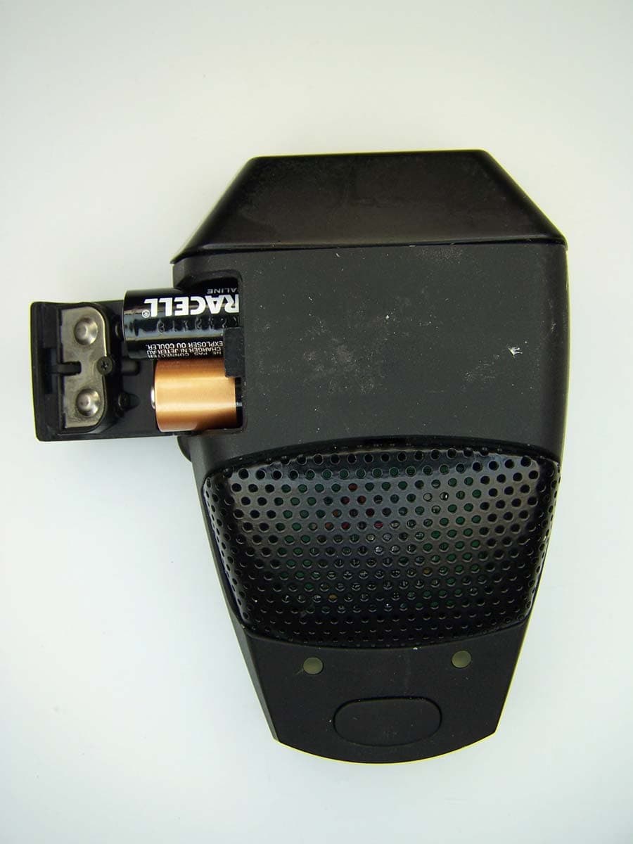
Click to zoom
Application Details
- Equipment Class
- UWB - Ultra Wideband Transmitter
- Date of Grant
- Feb 08, 2007
- Application Purpose
- Original Equipment
- Date of Application
- Oct 19, 2006
- Equipment Note
- Microphone
- Frequency Range
- 5610.00000000 - 7232.00000000
- Company
- Audio-Technica Corporation
- Country
- Japan
Documents & Files
Document Text
Text extracted from the exhibit documents filed with the FCC. Open a document above to read the original.
Users Manual
AUDIO TECHNICA SpectraPulse tm UWB WIRELESS MICROPHONE SYSTEM USER INFORMATION. INTRODUCTION Thank you for purchasing the Audio-Technica SpectraPulse wireless microphone system. It is our hope that the system will bring you years of trouble free pleasure and performance. Please follow the information contained in this manual closely as it will assist you in using your equipment effectively. PART 1. REGULATORY REQUIREMENTS. “This equipment may only be operated indoors. Operation outdoors is in violation of 47 U.S.C. 301 and could subject the operator to serious legal penalties.” “This device complies with Part 15 of the FCC rules. Operation is subject to the condition that this device does not cause harmful interference” “This device complies with INDUSTRY CANADA R.S.S. 210, en confomite avec IC: RSS- 210/CNR210. Operation is subject to the following conditions: (1) This device may not cause harmful interference and (2) This device must accept any interference received, including interference which may cause undesired operation.” “Note: This equipment has been tested and found to comply with the limits for a Class A digital device, pursuant to Part 15 of the FCC Rules. These limits are designed to provide reasonable protection against harmful interference when the equipment is operated in a commercial environment. This equipment generates, uses, and can radiate radio frequency energy and, if not installed and used in accordance with the instruction manual, may cause harmful interference to radio communications. Operation of this equipment in a residential area is likely to cause harmful interference in which case the user will be required to correct the interference at own expense.” Please note that your SpectraPulse system operates in a frequency band in a way which may make its use subject to certain FCC and other regulatory agency restrictions and licensing requirements. No changes or modifications may be made to this equipment except by the expressly approved responsible party for compliance. Changes or modifications could void the user’s authority to operate the equipment, and will also void Audio-Technica warranty coverage. For further information, Please contact your local office of the FCC as applicable. CAUTION! Electrical shock can result from removal of the receiver cover. Refer servicing to qualified service personnel. No user-serviceable parts inside. Do not expose to rain or moisture. The circuits inside the receiver and transmitter have been precisely adjusted for optimum performance and compliance with federal regulations. Do not attempt to open the receiver or transmitter. To do so will void the warranty, and may cause improper operation. Notice to individuals with implanted cardiac pacemakers or AICD devices: Any source of RF (radio frequency) energy may interfere with normal functioning of the implanted device. All wireless microphones have low-power transmitters (less than 0.05 watts output) which are unlikely to cause difficulty, especially if they are at least a few inches away. However, since a “body-pack” mic transmitter typically is placed against the body, we suggest attaching it at the belt, rather than in a shirt pocket where it may be immediately adjacent to the medical device. Note also that any medical-device disruption will cease when the RF transmitting source is turned off. Please contact your physician or medical-device provider if you have any questions, or experience any problems with the use of this or any other RF equipment. . CAUTION! The circuits inside the receiver and transmitter have been precisely adjusted for optimum performance and compliance with federal regulations. Do not attempt to open the receiver or transmitter. To do so will void the warranty, and may cause improper operation. PART 2. USING THE ACI707 AUDIO CONTROL INTERFACE The ACI707 Audio Control Interface operates via the safety-approved IEC power cord supplied for connection to 110-120V/50-60Hz AC power. You must change to an approved power cord for operation in non-U.S. locations. In this case, the ACI707 will operate properly from 100V-240V, 50/60Hz for worldwide use. Plug the ACI707 into the AC power source, but do not turn the power on yet. Connect a shielded CAT5 cable to the “Link In” RJ45 input connector on the rear of the ACI707. CAUTION – do not plug an Ethernet cable into this connector. Locate the section labeled “Audio Outputs” located at the bottom left portion on the rear of the ACI707. For each audio channel (corresponding to the number of boundary microphone transmitters used), connect a cable to the corresponding output on the rear of the ACI707. Up to 7 channels of audio output may be connected to your mixer or PA system from each ACI707. Depending upon the audio electronics input for your system , you may select the output level of the ACI707 to be either “Line” or “Mic” level. Locate the switch on the rear of the ACI707 (near the Audio Outputs) and set up or down as shown in the picture/label for correct output level. A light will illuminate on the front panel of the ACI707 to indicate whether the unit is operating with Line or Mic level output. Two ACI707 Audio Control Interfaces may be linked together in order to accomplish a full 14 channels of audio output from the system. When linking two systems, change the switch on the rear of the ACI707 to indicate whether it should be outputting channels 1-7 or channels 8-14. Locate the “Link Out” RJ45 connector and connect a shielded CAT5 cable from the channels 1-7 ACI707 to the “Link In” RJ45 connector on the ACI707 intended for channels 8-14. Again, remember this is not for Ethernet connection. The ACI707 Audio Control Interface is supplied with switches on the rear which can be changed in order to select the function of the soft-touch button on the MTU101 wireless boundary microphone. The switches are located in the upper left corner on the rear of the ACI707. You may set the switches so that the soft-touch butt…
Text truncated - open the document above for the full version.
Cover Letter(s)
Mr. Lyles: Sorry to have caused confusion. I have attached a revised letter to include operational description. I believe the files were supposed to be .pdf (I didn’t organize the first package). If there is anything else/or different that you require, please let me know. Best Regards, Jackie Green From: Generic Office of Engineering Technology [mailto:[email protected]] Sent: Wednesday, January 10, 2007 9:39 AM To: Jackie Green Subject: FCC Equipment Authorization System FCC Home | Search | Updates | E-Filing | Initiatives | For Consumers | Find People Office of Engineering and Technology Link to Federal Communications Commission Home Page Office of Engineering and Technology To: Jackie Green, From: Stan Lyles [email protected] FCC Application Processing Branch Applicant: Audio Technica Corp FCC ID: JFZMTU101 Form 731 Confirmation Number: EA988354 Date of Original E-Mail: 01/10/2007 Correspondence Reference Number:32363 1) Your requests confidentiality letter shows Block Diagrams, Schematic Diagrams, and Internal Photos. Your Exhibits shows Exhibit 4 Block Diagram, Exhibit 5 Schematics, Exhibit 9 Internal Photos and Exhibit 12 Operational Description are request confidentiality. Please clarify. 2) Please submit a new replacement confidentiality letter. The items indicated above must be submitted before processing can continue on the above referenced application. Failure to provide the requested information within 60 days of the original e-mail date may result in application dismissal pursuant to Section 2.917 (c) and forfeiture of the filing fee pursuant to section 1.1108. DO NOT reply to this e-mail by using the Reply button. In order for your response to be processed expeditiously, you must upload your response via the Internet at www.fcc.gov, Electronic Filing, OET Equipment Authorization Electronic Filing. If the response is submitted through Add Attachments, in order to expedite processing, a message which informs the processing staff that a new exhibit has been submitted must also be submitted via Submit Correspondence. Also, please note that partial responses increase processing time and should not be submitted. Any questions about the content of this correspondence should be directed to the e-mail address listed below the name of the sender.
External Photos
External Photographs
ID Label/Location Info
ONOFF 1 2 3 4 5 6 7 8 9 10 11 12 13 14 15 16 TX-107 Ultra Wideband Wireless Microphone Transmitter FCC ID: JFZTX107 spectrapulse TECHNOLOGY ™ ONOFF 1 2 3 4 5 6 7 8 9 10 11 12 13 14 15 16 spectrapulse TECHNOLOGY ™ TX-107 Ultra Wideband Wireless Microphone Transmitter FCC ID: JFZTX107 ONOFF 1 2 3 4 5 6 7 8 9 10 11 12 13 14 POWERCHANNEL ONOFF 1 2 3 4 5 6 7 8 9 10 11 12 13 14 15 16 POWERCHANNEL spectrapulse TECHNOLOGY ™ TX-107 Ultra Wideband Wireless Microphone Transmitter FCC ID: JFZTX107 spectrapulse ™ MODEL: MTU101 FCC ID: JFZMTU101 This device complies with part 15 of the FCC Rules. Operation is subject to the following two conditions: (1) This device may not cause harmful interference, and (2) this device must accept any interference received, including interference that may cause undesired operation. CANADA: Audio-Technica U.S., Inc. S/No. MADE IN U.S.A. MTU101 Bottom Label
Test Report
MET Laboratories, Inc. Safety Certification - EMI - Telecom Environmental Simulation 914 WEST PATAPSCO AVENUE ! BALTIMORE, MARYLAND 21230-3432 ! PHONE (410) 354-3300 ! FAX (410) 354-3313 The Nation’s First Licensed Nationally Recognized Testing Laboratory October 16, 2006 Audio-Technica 20300 Century Boulevard, Suite 250 Germantown, MD 20874-1132 Dear Jacquelynn Green, Enclosed is the EMC test report for compliance testing of the Audio-Technica, SpectraPulse Wireless Microphone System – Microphone Transceiver Unit (MTU101), tested to the requirements of Title 47 of the Code of Federal Regulations (CFR), Part 15.517, Subpart F for Ultra-Wideband Operation. Based on these results, MET Laboratories, Inc. certifies that the SpectraPulse Wireless Microphone System – Microphone Transceiver Unit (MTU101), tested as configured, meets the requirements and interference limitations for Digital Devices under Title 47 of the CFR, Part 15.517, Subpart F for Ultra-Wideband Operation. Thank you for using the services of MET Laboratories, Inc. If you have any questions regarding these results or if MET can be of further service to you, please feel free to contact me. Sincerely yours, MET LABORATORIES, INC. Sarah Kitlowski Documentation Department Reference: (\Audio-Technica\EMC19886A-FCC517) Certificates and reports shall not be reproduced except in full, without the written permission of MET Laboratories, Inc. While use of the National Voluntary Laboratory Accreditation Program (NVLAP) letters or the NVLAP Logo, the Standards Council of Canada Logo, A2LA, or the Nationally Recognized Testing Laboratory (NRTL) Letters in this report reflects MET Accreditation under these programs, these letters, logo, or statements do not claim product endorsement by these organizations or any Agency of the U.S. Government. This letter of transmittal is not a part of the attached report. MET Laboratories, Inc. Safety Certification - EMI - Telecom Environmental Simulation 914 WEST PATAPSCO AVENUE ! BALTIMORE, MARYLAND 21230-3432 ! PHONE (410) 354-3300 ! FAX (410) 354-3313 Certificates and reports shall not be reproduced except in full, without the written permission of MET Laboratories, Inc. Electromagnetic Compatibility Criteria Test Report For the Audio-Technica SpectraPulse Wireless Microphone System – Microphone Transceiver Unit (MTU101) FCC ID: JFZMTU101 Verified under the FCC Certification Rules contained in Title 47 of the CFR, Part 15.517, Subpart F for Ultra-Wideband Operation MET Report: EMC19886A-FCC517 October 16, 2006 Prepared For: Audio-Technica 20300 Century Boulevard, Suite 250 Germantown, MD 20874-1132 Prepared By: MET Laboratories, Inc. 914 West Patapsco Avenue Baltimore, MD 21230 Audio-Technica Electromagnetic Compatibility SpectraPulse Wireless Microphone System – Microphone Transceiver Unit MTU101 CFR Title 47, Part 15, Subpart F MET Report: EMC19886A-FCC517 © 2006, MET Laboratories, Inc. Page ii of v Electromagnetic Compatibility Criteria Test Report for the Audio-Technica SpectraPulse Wireless Microphone System – Microphone Transceiver Unit (MTU101) FCC ID: JFZMTU101 Title 47 of the CFR, Part 15.517, Subpart F for Ultra-Wideband Operation Dusmantha Tennakoon Sarah Kitlowski Project Engineer, Electromagnetic Compatibility Lab Documentation Department Engineering Statement: The measurements shown in this report were made in accordance with the procedures indicated, and the emissions from this equipment were found to be within the limits applicable. I assume full responsibility for the accuracy and completeness of these measurements, and for the qualifications of all persons taking them. It is further stated that upon the basis of the measurements made, the equipment tested is capable of operation in accordance with the requirements of Part 15, Section 15.517 of the FCC Rules under normal use and maintenance. Kevin Mehaffey, Manager, Electromagnetic Compatibility Lab Audio-Technica Electromagnetic Compatibility SpectraPulse Wireless Microphone System – Microphone Transceiver Unit MTU101 CFR Title 47, Part 15, Subpart F MET Report: EMC19886A-FCC517 © 2006, MET Laboratories, Inc. Page iii of v Table of Contents I. Executive Summary .................................................................................................................................................1 A. Purpose of Test ...................................................................................................................................................2 B. Executive Summary ............................................................................................................................................2 II. Equipment Configuration .......................................................................................................................................3 A. Overview.............................................................................................................................................................4 B. References...........................................................................................................................................................5 C. Test Site ..............................................................................................................................................................5 D. Description of Test Sample.................................................................................................................................5 E. Equipment Configuration....................................................................................................................................8 F. Support Equipment .............................................................................................................................................8 G. Mode of Operation..............................................................................................................................................9 H. …
Text truncated - open the document above for the full version.
Test Setup Photos
Multispectral Solutions, Inc. Electromagnetic Compatibility Criteria SpectraPulse Wireless Microphone System – Microphone Transceiver Unit MTU101 CFR Title 47, Part 15, Subpart F MET Report: EMC19886A-FCC 517 © 2006, MET Laboratories, Inc. Page 12 of 48 Photograph 1. View of Antenna on EUT Multispectral Solutions, Inc. Electromagnetic Compatibility Criteria SpectraPulse Wireless Microphone System – Microphone Transceiver Unit MTU101 CFR Title 47, Part 15, Subpart F MET Report: EMC19886A-FCC 517 © 2006, MET Laboratories, Inc. Page 13 of 48 Photograph 2. Second View of Antenna on EUT Multispectral Solutions, Inc. Electromagnetic Compatibility Criteria SpectraPulse Wireless Microphone System – Microphone Transceiver Unit MTU101 CFR Title 47, Part 15, Subpart F MET Report: EMC19886A-FCC 517 © 2006, MET Laboratories, Inc. Page 19 of 48 Electromagnetic Compatibility Criteria for Intentional Radiators § 15.209(a) Radiated Emission Photograph 3. Radiated Emission Test Setup – 30 MHz to 1 GHz Multispectral Solutions, Inc. Electromagnetic Compatibility Criteria SpectraPulse Wireless Microphone System – Microphone Transceiver Unit MTU101 CFR Title 47, Part 15, Subpart F MET Report: EMC19886A-FCC 517 © 2006, MET Laboratories, Inc. Page 20 of 48 Photograph 4. Radiated Emission Test Setup - above 1 GHz Multispectral Solutions, Inc. Electromagnetic Compatibility Criteria SpectraPulse Wireless Microphone System – Microphone Transceiver Unit MTU101 CFR Title 47, Part 15, Subpart F MET Report: EMC19886A-FCC 517 © 2006, MET Laboratories, Inc. Page 25 of 48 Photograph 5. Radiated Emissions Test Setup Multispectral Solutions, Inc. Electromagnetic Compatibility Criteria SpectraPulse Wireless Microphone System – Microphone Transceiver Unit MTU101 CFR Title 47, Part 15, Subpart F MET Report: EMC19886A-FCC 517 © 2006, MET Laboratories, Inc. Page 29 of 48 Photograph 6. Radiated Emissions Test Setup Multispectral Solutions, Inc. Electromagnetic Compatibility Criteria SpectraPulse Wireless Microphone System – Microphone Transceiver Unit MTU101 CFR Title 47, Part 15, Subpart F MET Report: EMC19886A-FCC 517 © 2006, MET Laboratories, Inc. Page 32 of 48 Photograph 7. Radiated Emissions Test Setup
Contact Information
Applicant
Fumio Kamimura(General Manager, Engineering Planning Division)
Test Firm
EUROFINS ELECTRICAL AND ELECTRONIC TESTING NA, INCGreg Kovolenko
Technical Specifications
| # | Rule Parts | Frequency Range | Power Output |
|---|---|---|---|
| 1 | 15F | 5.61 GHz - 7.23 GHz | - |
Other Applications from Audio-Technica Corporation
JFZDT3207DF2
Apr 06, 2026DESK STAND TRANSMITTER
Equipment Class
DWM - Part 15 Wireless MicrophoneJFZT210CS
Jul 17, 2024UniPak Transmitter
Equipment Class
TLD - Licensed LPAS DeviceJFZT220CS
Jul 17, 2024Handheld Transmitter
Equipment Class
TLD - Licensed LPAS DeviceJFZCKS50TW2R
Jun 10, 2024Wireless Headphones
Equipment Class
DTS - Digital Transmission SystemJFZCKS30TWPR
Apr 02, 2024Wireless Headphones
Equipment Class
DSS - Part 15 Spread Spectrum Transmitter