JFZR2100ADWIRELESS MIC RECEIVER
Audio-Technica Corporation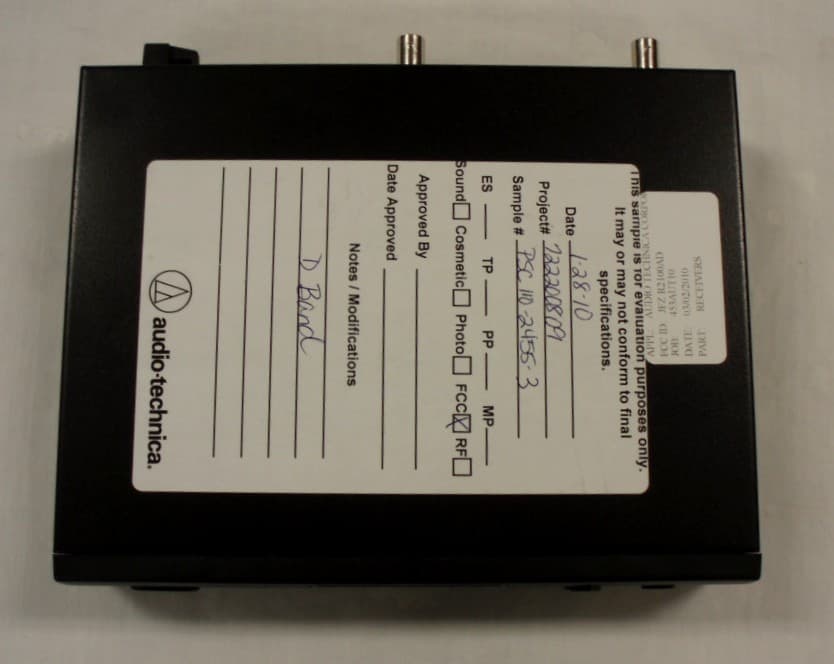
Click to zoom
Application Details
- Equipment Class
- CRR - Superregenerative Receiver
- Date of Grant
- Jun 01, 2010
- Application Purpose
- Original Equipment
- Date of Application
- Jun 01, 2010
- Equipment Note
- WIRELESS MIC RECEIVER
- Frequency Range
- 656.12500000 - 678.50000000
- Company
- Audio-Technica Corporation
- Country
- Japan
Documents & Files
Document Text
Text extracted from the exhibit documents filed with the FCC. Open a document above to read the original.
Users Manual
2000 Series Frequency-agile True Diversity UHF Wireless System Installation and Operation 2000 Series Installation and Operation 2 This device complies with part 15 of the FCC Rules. Operation is subject to the condition that this device does not cause harmful interference. This device complies with INDUSTRY CANADA R.S.S. 210, en conformité avec IC: RSS-210/CNR210. Operation is subject to the following conditions: 1) This device may not cause harmful interference and 2) this device must accept any interference received, including interference which may cause undesired operation. CAUTION! Electrical shock can result from removal of the receiver cover. Refer servicing to qualified service personnel. No user- serviceable parts inside. • To prevent fire or shock hazard, do not expose this appliance to rain or moisture. • To prevent fire, do not place any naked flame sources (such as lighted candles) on the apparatus. • To prevent fire, do not cover the ventilation of the apparatus with newspaper, tablecloths, curtains etc. • Do not expose this apparatus to drips or splashes. • Do not place any objects filled with liquids, such as vases, on the apparatus. • Do not install this apparatus in a confined space such as a bookcase or similar unit. • The apparatus should be located close enough to the AC outlet so that you can easily grasp the AC adapter at any time. In case of emergency, disconnect the AC adapter quickly. • Danger of explosion if battery is incorrectly replaced. Replace only with the same or equivalent type. • Always consider environmental issues and follow your local regulations when disposing of batteries. Do not expose batteries to excessive heat. The circuits inside the receiver and transmitter have been precisely adjusted for optimum performance and compliance with federal regulations. Do not attempt to open the receiver or transmitter. To do so will void the warranty, and may cause improper operation. Notice to individuals with implanted cardiac pacemakers or AICD devices: Any source of RF (radio frequency) energy may interfere with normal functioning of the implanted device. All wireless microphones have low-power transmitters (less than 0.05 watts output) which are unlikely to cause difficulty, especially if they are at least a few inches away. However, since a “body-pack” mic transmitter typically is placed against the body, we suggest attaching it at the belt, rather than in a shirt pocket where it may be immediately adjacent to the medical device. Note also that any medical-device disruption will cease when the RF transmitting source is turned off. Please contact your physician or medical-device provider if you have any questions, or experience any problems with the use of this or any other RF equipment. RF Interference Please note that wireless frequencies are shared with other radio services. According to Federal Communications Commission regulations, “Wireless microphone operations are unprotected from interference from other licensed operations in the band. If any interference is received by any Government or non Government operation, the wireless microphone must cease operation...” If you need assistance with operation or frequency selection, please contact your dealer or Audio-Technica. Extensive wireless information also is available at www.audio-technica.com. Thank you for choosing an Audio-Technica professional wireless system. You have joined thousands of other satisfied customers who have chosen our products because of their quality, performance and reliability. This Audio-Technica wireless microphone system is the successful result of years of design and manufacturing experience. Each 2000 Series wireless system provides a choice of 10 PLL synthesized UHF frequencies in one of five UHF frequency ranges, available for flexible performance in a wide variety of regions worldwide: Frequency Range Band D 656.125 – 678.500 MHz Band E 800.550 – 813.150 MHz Band F 854.900 – 864.900 MHz Band G 722.125 – 744.500 MHz Band I 487.125 – 506.500 MHz The band letter reference at the end of 2000 Series Stock Numbers indicates what band system/component operates in. For simplicity, model numbers used throughout this manual will reference only the basic model number without the band indications. Each wireless system includes a receiver and either a body-pack or handheld transmitter. UniPak ® body-pack transmitter systems include accessory microphones for particular applications. All A-T Wireless Essentials ® microphones and cables, available separately, are pre- terminated for use with any Audio-Technica 2000 Series wireless system. The ATW-R2100a receiver features true diversity reception. Two antennas feed two completely independent RF sections on the same frequency; automatic logic circuitry continuously compares and selects the superior received signal, providing better sound quality and reducing the possibility of interference and dropouts. The receiver also offers a switchable output attenuator to reduce the level of the output signal by 12 dB for flexible use with a variety of system configurations. Switchable antenna power is also provided. Soft-touch controls provide convenient access to selection of operating frequency and automatic scanning, while an LCD information display provides constant monitoring of system operation. The receiver is half-width for a standard 1U 19" rack mount; rack-mount adapters are included. Two receivers can be mounted side by side, using an optional AT8630 joining-plate kit. The versatile ATW-T210a UniPak ® body-pack transmitter has both low- and high-impedance inputs plus a bias connection, for use with dynamic and electret condenser microphones, as well as Hi-Z instrument pickups. The UniPak ® transmitter also offers separate trim controls for instrument and microphone, plus switchable high/low RF power. The ATW-T220a handheld dynamic microphone/transmitter features the same element used in the PRO 41 dynamic handheld microphone created f…
Text truncated - open the document above for the full version.
External Photos
APPLICANT: AUDIO TECHNICA COPRORATION FCC ID: JFZR2100AD EXTERNAL PHOTOS
Internal Photos
APPLICANT: AUDIO TECHNICA COPRORATION FCC ID: JFZR2100AD INTERNAL PHOTOS
Test Report
FCC PART 15 B SUBPART B RECEIVER TEST REPORT Applicant AUDIO TECHNICA CORPORATION Address 2206 NARUSE, MACHIDA TOKYO 194 JAPAN FCC ID JFZR2100AD Product Description WIRELESS MIC RECEIVER Date Sample Received 3/2/2010 Date Tested 3/16/2010 Tested By Nam Nguyen Approved By Mario R. de Aranzeta Report Number 453AUT10TestReport.doc Test Results PASS FAIL THE ATTACHED REPORT SHALL NOT BE REPRODUCED EXCEPT IN FULL WITHOUT THE WRITTEN APPROVAL OF TIMCO ENGINEERING, INC. 849 NW State Road 45 Newberry, Fl 32669 USA Phone: 888.472.2424 or 352.472.5500 Fax: 352.472.2030 Email: [email protected] Website: www.timcoengr.com Certificate # 0955-01 APPLICANT: AUDIO TECHNICA CORPORATION FCC ID: JFZR2100AD REPORT: A\AudioTechnica_JFZ\453AUT10\453AUT10TestReport.doc Page 2 of 12 rev 2 mdea 09.20.2008 TABLE OF CONTENTS GENERAL REMARKS ........................................................................................................................... 3 REPORT SUMMARY............................................................................................................................. 4 TEST ENVIRONMENT .......................................................................................................................... 4 TEST SETUP SUMMARY ...................................................................................................................... 4 DUT SPECIFICATION .......................................................................................................................... 5 TEST EQUIPMENT LIST ...................................................................................................................... 6 TEST PROCEDURES ........................................................................................................................... 7 RADIATED SPURIOUS EMISSIONS ..................................................................................................... 8 POWER LINE CONDUCTED INTERFERENCE ..................................................................................... 9 RADIATED EMISSIONS TEST SETUP PHOTO ................................................................................... 11 POWERLINE CONDUCTED TEST SETUP PHOTO ............................................................................. 12 APPLICANT: AUDIO TECHNICA CORPORATION FCC ID: JFZR2100AD REPORT: A\AudioTechnica_JFZ\453AUT10\453AUT10TestReport.doc Page 3 of 12 rev 2 mdea 09.20.2008 GENERAL REMARKS The attached report shall not be reproduced except in full without the written permission of Timco Engineering Inc. The test results relate only to the items tested. Summary The device under test does: fulfill the general approval requirements as identified in this test report not fulfill the general approval requirements as identified in this test report Attestations This equipment has been tested in accordance with the standards identified in this test report. To the best of my knowledge and belief, these tests were performed using the measurement procedures described in this report. All instrumentation and accessories used to test products for compliance to the indicated standards are calibrated regularly in accordance with ISO 17025: 2005 requirements. Certificate # 0955-01 I attest that the necessary measurements were made, under my supervision, at: Timco Engineering Inc. 849 NW State Road 45 Newberry, Fl 32669 Authorized Signatory Name: Mario de Aranzeta C.E.T. Compliance Engineer/ Lab. Supervisor Date: 5/5/2010 APPLICANT: AUDIO TECHNICA CORPORATION FCC ID: JFZR2100AD REPORT: A\AudioTechnica_JFZ\453AUT10\453AUT10TestReport.doc Page 4 of 12 rev 2 mdea 09.20.2008 REPORT SUMMARY Disclaimer The test results only relate to the item tested. Applicable Rule(s) Pt 15.109, Pt 15.107, ANSI C63.4: 2003 Related Report None TEST ENVIRONMENT Test Facility Timco Engineering, Inc. 849 NW State Road 45 Newberry, FL 32669 USA. Test Condition in the laboratory Temperature: 26ºC Relative humidity: 50% TEST SETUP SUMMARY Test Setup Diagram/ Description The DUT was placed on the turntable per setup per ANSI C63.4: 2003. A test set up photo is provided for clarification. Deviation from the standard/procedure No deviation Modification of DUT No modification APPLICANT: AUDIO TECHNICA CORPORATION FCC ID: JFZR2100AD REPORT: A\AudioTechnica_JFZ\453AUT10\453AUT10TestReport.doc Page 5 of 12 rev 2 mdea 09.20.2008 DUT SPECIFICATION DUT Description WIRELESS MIC RECEIVER FCC ID JFZR2100AD DUT Power Source 110–120Vac/50– 60Hz DC Power Battery Operated Exclusively Test Item Prototype Pre-Production Production Type of Equipment Fixed Mobile Portable Laboratory Test Conditions Temperature: 26ºC Humidity: 55% Modifications to DUT: No Yes (explanation below) APPLICANT: AUDIO TECHNICA CORPORATION FCC ID: JFZR2100AD REPORT: A\AudioTechnica_JFZ\453AUT10\453AUT10TestReport.doc Page 6 of 12 rev 2 mdea 09.20.2008 TEST EQUIPMENT LIST Device Manufacturer Model Serial Number Cal/Char Date Due Date 3-Meter OATS TEI N/A N/A Listed 2/5/09 2/5/12 3-Meter Semi- Anechoic Chamber Panashield N/A N/A Listed 5/11/07 5/10/10 Analyzer Open- Frame Tower Preamplifier HP 8449B 3008A01075 CAL 7/22/09 7/22/11 Analyzer Open- Frame Tower Quasi- Peak Adapter HP 85650A 2043A00305 CAL 10/26/09 10/26/11 Analyzer Open- Frame Tower RF Preselector HP 85685A 3107A01282 CAL 7/22/09 7/22/11 Analyzer Open- Frame Tower Spectrum Analyzer HP 8566B/8566 2A 2627A03154 2648A14276 CAL 7/22/09 7/22/11 Antenna: Log- Periodic Electro-Metrics LPA-25 1122 CAL 12/15/08 12/15/10 Power Line Coupling/Decoupling Network Fischer Custom Communications FCC-801- M2-16A 01048 CHAR 11/25/08 11/25/10 Power Line Coupling/Decoupling Network Fischer Custom Communications FCC-801- M3-16A 01060 CHAR 11/25/08 11/25/10 APPLICANT: AUDIO TECHNICA CORPORATION FCC ID: JFZR2100AD REPORT: A\AudioTechnica_JFZ\453AUT10\453AUT10TestReport.doc Page 7 of 12 rev 2 mdea 09.20.2008 TEST PROCEDURES Power line conducted Emission: The test procedure used was ANSI C63.4-2003. The spectrum …
Text truncated - open the document above for the full version.
Contact Information
Applicant
Fumio Kamimura(General Manager, Engineering Planning Division)
Test Firm
Timco Engineering, Inc.Bruno Clavier
Technical Specifications
| # | Rule Parts | Frequency Range | Power Output |
|---|---|---|---|
| 1 | 15B | 656.125 MHz - 678.5 MHz | - |
Other Applications from Audio-Technica Corporation
JFZDT3207DF2
Apr 06, 2026DESK STAND TRANSMITTER
Equipment Class
DWM - Part 15 Wireless MicrophoneJFZT210CS
Jul 17, 2024UniPak Transmitter
Equipment Class
TLD - Licensed LPAS DeviceJFZT220CS
Jul 17, 2024Handheld Transmitter
Equipment Class
TLD - Licensed LPAS DeviceJFZCKS50TW2R
Jun 10, 2024Wireless Headphones
Equipment Class
DTS - Digital Transmission SystemJFZCKS30TWPR
Apr 02, 2024Wireless Headphones
Equipment Class
DSS - Part 15 Spread Spectrum Transmitter