JFZR220Communications Receiver
Audio-Technica Corporation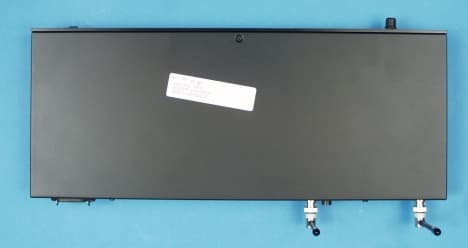
Click to zoom
Application Details
- Equipment Class
- CXX - Communications Rcvr for use w/ licensed Tx and CBs
- Date of Grant
- Oct 17, 2000
- Application Purpose
- Original Equipment
- Date of Application
- Oct 18, 2000
- Equipment Note
- Communications Receiver
- Frequency Range
- 728.00000000 - 741.00000000
- Company
- Audio-Technica Corporation
- Country
- Japan
Documents & Files
Document Text
Text extracted from the exhibit documents filed with the FCC. Open a document above to read the original.
Users Manual
Audio-Technica Model ESW-R220/210 and T211/T214 UHF Wireless Microphone System User Information DRAFT Introduction Thank you for purchasing the ESW series wireless microphone system. It is our hope that the system will bring you years of trouble free pleasure and performance. Please follow the information contained in this manual closely as it will assist you in using your equipment effectively. Part 1. Regulatory Requeirements FCC PART 15 COMPLIANCE STATEMENT CANADA RSS-210 COMPLIANCE STATEMENT “This device complies with Part 15 of the FCC rules. Operation is subject to the condition that this device does not cause harmful interference.” “This device complies with INDUSTRY CANADA R.S.S.210, en conformite avec IC:RSS-210/CNR210. Operation is subject to the following conditions: (1) This device may not cause harmful interference and (2) this device must accept any interference received, including interference which may cause undesired operation.” Please not that your ESW Series system operates in a frequency band and in a way which makes is use subject to certain FCC and other regulatory restrictions and licensing requirements. For further information, please contact your local office of the FCC as applicable. Part 2. Using the ESW-T211 Beltpack Transmitter The beltpack transmitter operates on 2 “AA” size batteries. Please make sure that your batteries are fresh. We recommend that you use Alkaline batteries and that you avoid using NiCad if possible. Insert batteries into the battery compartment and slide the battery compartment back into place. Open the rubber cover over the channels selector switch and set the group and channel to the corresponding channels as set on the receiver. Replaces the cover over the rotary switches. Connect your microphone or guitar cables to the connector on the top sides of the transmitter. If you want the low cut to be on, switch this in. Turn the transmitter switch to the on position. Confirm that the receiver is receiving RF and that the audio is passing through the receiver. You are now set to use the system. Part 3. Using the ESW-T214 Handheld Transmitter The handheld transmitter operates on 2 “AA” size batteries. Please make sure that your batteries are fresh. We recommend that you use Alkaline batteries and that you avoid using NiCad if possible. Insert the batteries into the battery compartment and slide the battery compartment cover back into place. To change the channel of operation, unscrew the battery compartment cover and pull the cover back. Locate the channel selector rotary switches. Set the group and channel to the corresponding channel as set on the receiver. Replace the cover over the rotary switches. Turn the transmitter switch to the on position. Confirm that the receiver is receiving RF. Speak directly into the microphone and confirm that audio is passing through the receiver. You are now set to use the system. Part 4. Using the ESW-R210/R220 Receiver The ESW-R210/R220 receivers operate on a 110 VAC plug. Plug the unit into an AC outlet. Push the on/off switch. Confirm that the LED comes on. Check the group and channel setting to confirm that they correspond to the settings of the transmitter. Connect the balanced or unbalanced audio output to your mixer PA system. Adjust the volume setting to the desired level. Speak into the microphone and listen to the audio out at the speaker. If satisfied with the audio quality, you can use the system. ESW Operation specification ESW-R210/R220 Operating Band:728.125-740.500MHz Type of Reception: F3E Frequency Response: 100Hz to 15kHz No. of Channels:100 Audio Output Power: Line level, Unbalanced Signal to Noise Ratio: >80 dBa Antenna Connector: BNC-R type Selectivity: > 50dB Spurious Rejection: > 50dB Receiver Sensitivity: </= uV for 60 dB S/N, (IEC weighted) ESW-T211 Beltpack Transmitter Operating Band:728.125-740.500MHz Type of Modulation:FM, F3E Frequency Response:100Hz to 15kHz No. of Channels:100 Transmitter Power:10 mW nominal Spurious Emissions:Under federal regulations Battery:2 x 1.5V AA size ESW-T214 Handheld Transmitter Operating Band:728.125-740.500MHz Type of Modulation:FM, F3E Frequency Response:100Hz to 15kHz No. of Channels:100 Transmitter Power:10mW nominal Spurious Emissions:Under federal regulations Battery:2 x 1.5V AA
External Photos
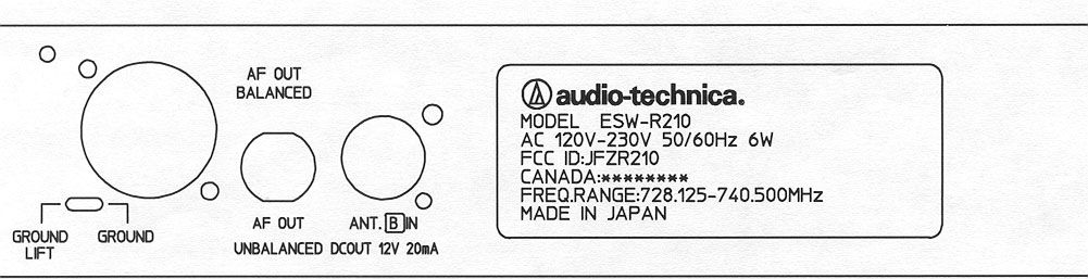
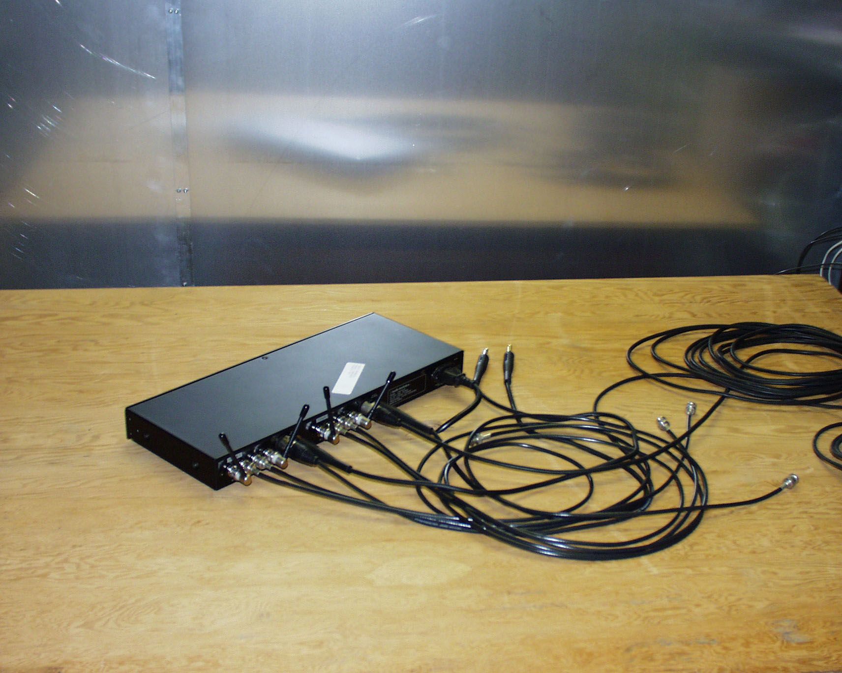
Front View Back View Side View 1 Side View 2 Top View Botto m View
Internal Photos
Circuit Board, Component Side Circuit Board witho ut Shield Circuit Board , Track Side
Test Report
ENGINEERING STATEMENT In Regard to Measurements on AUDIO-TECHNICA U.S., INC. MODEL: ESW-R220 FCC ID: JFZR220 A. INTRODUCTION Hyak Laboratories, Inc. has been authorized by Audio Technica to perform measurements on a receiver to determine compliance with FCC rules, Part 15, Subpart B. The receiver operates in the 728 - 741 MHz band and is intended for use with a wireless microphone. B. DESCRIPTION OF RECEIVER The receiver incorporates a dual diversity, dual con- version, super-heterodyne design. The following information is supplied as requested in FCC Bulletin OCE 24: 1. Service in which the receiver will be used: Part 15. (74). 2. Function of receiver: Wireless Microphone Receiver. 3. Tuning range: 728 - 741 MHz. 4. IF used: 54.25 MHz, 10.7 5. Fundamental frequency of principal oscillators in the receiver. First local oscillator: (Fo+54.25) MHz (PLL). Second local oscillator 43.55 MHz. C. DESCRIPTION OF MEASUREMENT FACILITIES A description of the Hyak Laboratories' radiation test facility is a matter of record with the FCC. The facility was accepted for radiation measurements from 30 to 1000 MHz on October 1, 1976, and is currently listed as an accepted site. D. DESCRIPTION OF MEASUREMENT PROCEDURE: RADIATED EMISSIONS Measurements of receiver radiation field strength were made using ANSI C63.4 (1992) the basic procedure. Measurements were made with 3 meter spacing between the receiver under test and the test equipment antenna. The antenna(s) connected to the receiver under test consisted of vertically polarized, antennas approximately 5 cm long. The receiver under test was placed on a rotatable table 80 cm in height. Measurement of field strength was made through use of a Tektronix 494P spectrum analyzer in conjunction with Singer DM- 105A series or EMCO 3221 calibrated dipoles or EMCO 3115 DRG horn. For each spurious emission identified between 30 to 2000 MHz, the test sample was rotated for maximum pickup, the test antenna varied in elevation, and the test antenna polarization shifted between horizontal to vertical in order to maximize observed signals. E. REPORT OF RADIATED EMISSIONS Table 1 lists the frequency and amplitude of all signals observed from 30 to 2000 MHz that were within 20 dB of the limits of paragraph 15.109 of the FCC Rules for lower, mid and upper operating channels. 2 TABLE 1 RADIATED SPURIOUS EMISSIONS Measured at 3 meters PART 15(B) PARA. 15.109 Frequency Frequency To Which of Meter Antenna Field 1 Tuned Emission Reading Factor Intensity FCC Limit dB to (MHz) (MHz) (dBm) (dB) uV/m @ 3m uV/m @ 3m Limit 728.125 782.376 -86.8 20.9 114 200 -4.9 734.386 788.626 -87.2 20.9 108 200 -5.3 740.540 794.753 -87.2 20.9 108 200 -5.3 All* 794.630 -93.6 20.9 52 200 -12 Note 1: uV/m = Log -1dBu/m 20 dBu = dBm + antenna factor + 107 *Present independent of channel frequency RADIATED SPURIOUS EMISSIONS FCC ID: JFZR220 TABLE 1 3 F. PROCEDURE - AC LINE CONDUCTED SPURIOUS The procedures of MP-4 were followed. Power line conducted spurious were measured from .45 to 30 MHz using an IEEE 213 line impedance stabilization network, (LISN), modified for 50 uH network per Paragraph 5.3, of 15.840, Appendix A. The device under test was operated in modes which maximized observed spurious. An Advantest R3361A spectrum analyzer was used as the detector. Measurements were made with a 9 kHz bandwidth; quasi-peak (CISPR) detector values are shown. A 120 second scan time was used. G. DATA - AC LINE CONDUCTED SPURIOUS Plots of the spectrum analyzer display are shown in Figures 1a and 1b for both operating channels. All ac-line conducted spurious were within the 48 dBu requirement of Para 15.107. Horizontal axis is .45 to 30 MHz centered at 15.22 MHz; vertical axis is 10 db/div with the top of the screen representing 60 dBu. (For the 50 ohm system used, the 250 microvolt FCC limit is equivalent to 48 dBu as shown by the green line.) H. STATEMENT Technical test data are from tests performed by me or under my supervision. My qualifications are a matter of record with the Federal Communications Commission. I personally attest to the accuracy of the test data submitted as a part of this engineering statement. __________________________________ Rowland S. Johnson Dated: September 6, 2000 4 AC LINE CONDUCTED SPURIOUS FCC ID: JFZR220 FIGURE 1a (Left LISN) 5 AC LINE CONDUCTED SPURIOUS FCC ID: JFZR220 FIGURE 1b (Right LISN) 6
Contact Information
Applicant
Fumio Kamimura(General Manager, Engineering Planning Division)
Test Firm
Hyak Laboratories, Inc.Rowland Johnson
703-451-1188
Technical Specifications
| # | Rule Parts | Frequency Range | Power Output |
|---|---|---|---|
| 1 | 15B | 728 MHz - 741 MHz | - |
Other Applications from Audio-Technica Corporation
JFZDT3207DF2
Apr 06, 2026DESK STAND TRANSMITTER
Equipment Class
DWM - Part 15 Wireless MicrophoneJFZT210CS
Jul 17, 2024UniPak Transmitter
Equipment Class
TLD - Licensed LPAS DeviceJFZT220CS
Jul 17, 2024Handheld Transmitter
Equipment Class
TLD - Licensed LPAS DeviceJFZCKS50TW2R
Jun 10, 2024Wireless Headphones
Equipment Class
DTS - Digital Transmission SystemJFZCKS30TWPR
Apr 02, 2024Wireless Headphones
Equipment Class
DSS - Part 15 Spread Spectrum Transmitter