JFZR250VHF WIRELESS RECEIVER
Audio-Technica Corporation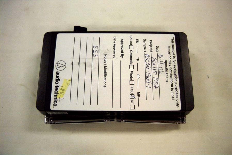
Click to zoom
Application Details
- Equipment Class
- CXX - Communications Rcvr for use w/ licensed Tx and CBs
- Date of Grant
- Jul 25, 2006
- Application Purpose
- Original Equipment
- Date of Application
- Jul 25, 2006
- Equipment Note
- VHF WIRELESS RECEIVER
- Frequency Range
- 169.00000000 - 172.00000000
- Company
- Audio-Technica Corporation
- Country
- Japan
Documents & Files
Document Text
Text extracted from the exhibit documents filed with the FCC. Open a document above to read the original.
Users Manual
200 Series Owners Manual v.1 7-6-06 Page 1 of 9 ATW-251 UniPak™ System ATW-251/G Guitar System ATW-251/H Headworn Microphone System ATW-251/L Lavalier Microphone System ATW-252 Handheld Microphone System This device complies with part 15 of the FCC Rules. Operation is subject to the condition that this device does not cause harmful interference. This device complies with INDUSTRY CANADA R.S.S. 210, en conformité avec IC: RSS-210/CNR210. Operation is subject to the following conditions: 1) This device may not cause harmful interference and 2) this device must accept any interference received, including interference which may cause undesired operation. CAUTION! Electrical shock can result from removal of the receiver cover. Refer servicing to qualified service personnel. No user-serviceable parts inside. Do not expose to rain or moisture. The circuits inside the receiver and transmitter have been precisely adjusted for optimum performance and compliance with federal regulations. Do not attempt to open the receiver or transmitter. To do so will void the warranty, and may cause improper operation. Notice to individuals with implanted cardiac pacemakers or AICD devices : Any source of RF (radio frequency) energy may interfere with normal functioning of the implanted device. All wireless microphones have low-power transmitters (less than 0.05 watts output) which are unlikely to cause difficulty, especially if they are at least a few inches away. However, since a “body-pack” mic transmitter typically is placed against the body, we suggest attaching it at the belt, rather than in a shirt pocket where it may be immediately adjacent to the medical device. Note also that any medical-device disruption will cease when the RF transmitting source is turned off. Please contact your physician or medical-device provider if you have any questions, or experience any problems with the use of this or any other RF equipment. 200 Series Owners Manual v.1 7-6-06 Page 2 of 9 Introduction Thank you for choosing an Audio-Technica professional wireless system. You have joined thousands of other satisfied customers who have chosen our products because of their quality, performance and reliability. This wireless microphone system is the successful result of years of design and manufacturing experience. Each 200 Series professional VHF wireless system includes a receiver and either a body-pack transmitter or a handheld microphone/transmitter on a specific crystal-controlled frequency. ATW-251 UniPak™ body-pack transmitter systems include models pre-packaged with either an AT-GCW guitar cable (/G), a PRO 8HEcW headworn microphone (/H), or a lavalier mic (/L) for particular applications. All A-T Wireless Essentials™ microphones and cables, available separately, are pre-terminated for use with any ATW-251 system. Because 200 Series packaging is designed to hold all versions of the system, some compartments in the carton are intentionally left empty. The ATW-R250 receiver includes a space-saving switching power supply that automatically adapts to changes in mains voltage. Unlike bulky linear power supplies, this switching power supply is lightweight and compact; it uses only a single outlet space. The versatile ATW-T201 UniPak body-pack transmitter has both a high- impedance input for instruments, and a low-impedance input with bias connection for use with dynamic and electret condenser microphones. The ATW- T202 handheld transmitter features a unidirectional dynamic microphone element. Both the body-pack and handheld transmitters use internal 9-volt batteries and have Off/Standby/On switches, input Trim (level) adjustments and battery-save switches. Receiver Installation Location For best operation the receiver should be at least 3' (1 m) above the ground and at least 3' (1 m) away from a wall or metal surface to minimize reflections. Keep the receiver antennas away from noise sources such as digital equipment, motors, automobiles and neon lights, as well as away from large metal objects. In multi-channel systems, position receivers at least 3' (1 m) apart and keep operating transmitters at least 6' (2 m) from the receivers to help assure maximum RF performance. Output Connection The receiver provides unbalanced, aux-level output from a 1/4" TS (“mono”) phone jack; an output cable is not included. Use a shielded audio cable with 1/4" 200 Series Owners Manual v.1 7-6-06 Page 3 of 9 phone plug to connect the receiver’s AF Out jack to the mixer/amplifier’s aux- level input. Power Connection Connect the DC plug on the included AC power adapter to the DC power input on the back of the receiver. Secure the cord over the cord hook on the back of the receiver, to keep the plug from being detached by an accidental tug on the cord. Then plug the adapter into a standard 120 Volt 60 Hz AC power outlet. (Note that the receiver has no power Off/On switch. The receiver will be energized whenever the power adapter is connected and plugged into the AC outlet. Unplug the power supply from the AC outlet when the system is not in use – both for safety, and to conserve energy.) Antennas A novel “dipole” antenna system on the receiver improves operation by providing a “ground” element in addition to the usual “signal” element. Position the two antennas at 90° in the form of a “V,” or position the left (“signal”) antenna vertically and the right (“ground”) antenna horizontally, in the shape of an “L” (Fig. B). Use the position that performs better in your operating environment. Be certain to extend both antennas to their full 15" (38 cm) length by holding them at their bases and pulling out on their caps. Both antenna elements may be swiveled to the left and right, but do not attempt to rotate them in a screwing/unscrewing motion. To do so may damage the antenna and/or receiver. For best performance, locate the receiver so its antennas are in direct line-of- sight to the transmitter’s likely operating position. Receiver Controls and Functions F…
Text truncated - open the document above for the full version.
Cover Letter(s)
Audio-Technica U.S., Inc. 1221 Commerce Drive Phone: 330-686-2600 [email protected] Stow, OH 44224-1760 Fax: 330-688-3752 May 18, 2006 Equipment Authorization Division Office of Engineering and Technology Federal Communications Commission 7435 Oakland Mills Road Columbia, MD 21046 Ref: FCC ID: JFZR250 Request for Confidentiality Dear Sirs: With regard to the referenced application, Audio-Technica, is requesting confidentiality of certain sections of the accompanying documents. The documents for which Audio Technica is requesting confidentiality are: Schematic for ATW-R250 wireless receiver Block diagram for ATW-R250 wireless receiver This request is made under the provisions of Section 0.457(d) of the Commission’s Rules, and Section 552(b)(4) of the Freedom of Information Act. The material for which confidentiality is requested falls within the scope of Section 552(b)(4) as trade secrets and includes material covered by Section 0.459 of the Commission’s Rules. Sincerely, Jacquelynn Green Vice President R&D Audio-Technica U.S., Inc.
External Photos
AUDIO TECHNICA CORP. FCC ID: JFZR250 EXTERNAL PHOTOS
ID Label/Location Info
This device complies with part 15 of the FCC rules. Operation is subject to the following two conditions: (1) This device may not cause harmful interference, and (2) this device must accept any interference received, including interference that may cause undesired operation
Internal Photos
AUDIO TECHNICA CORP. FCC ID: JFZR250 INTERNAL PHOTOS
Test Report
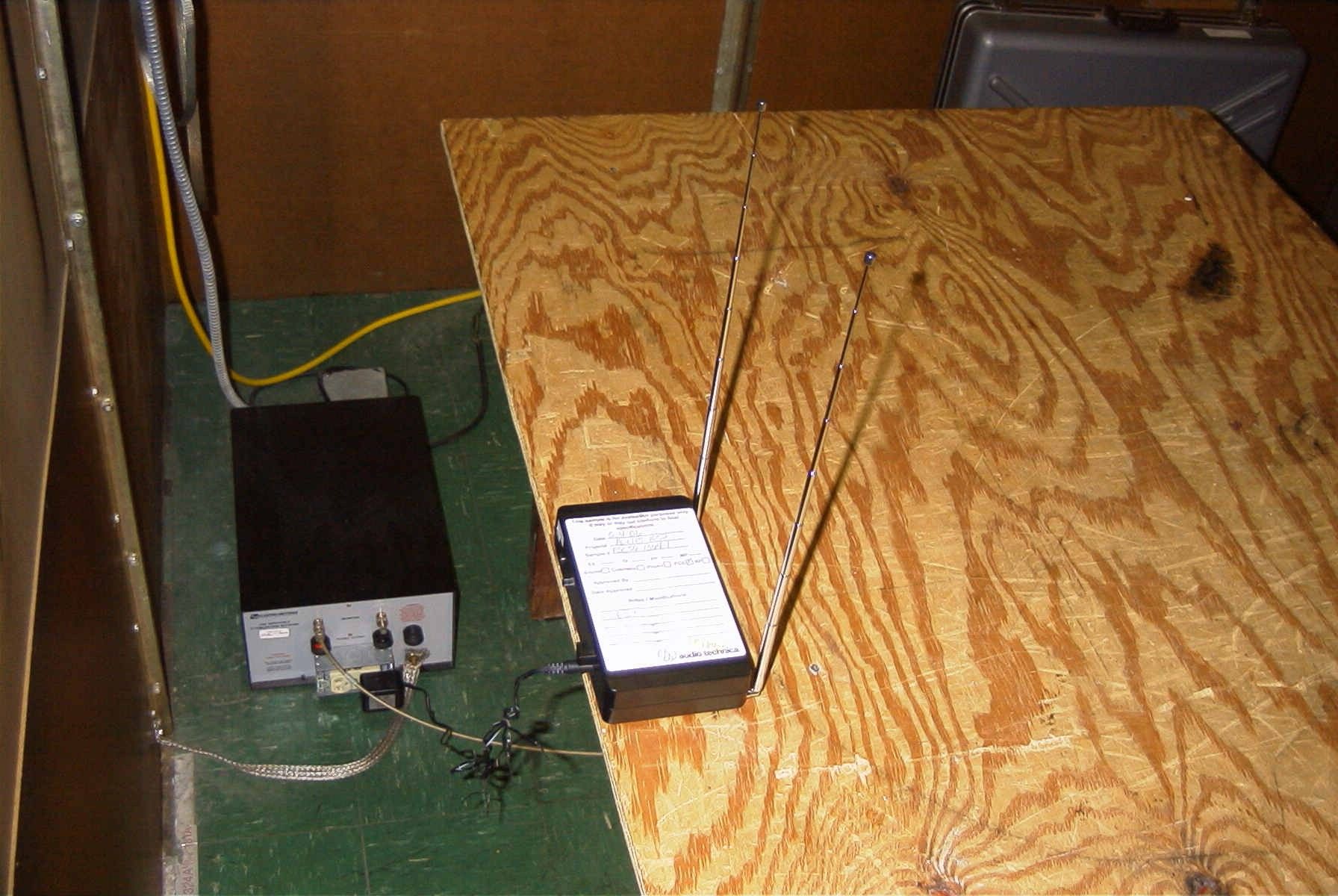
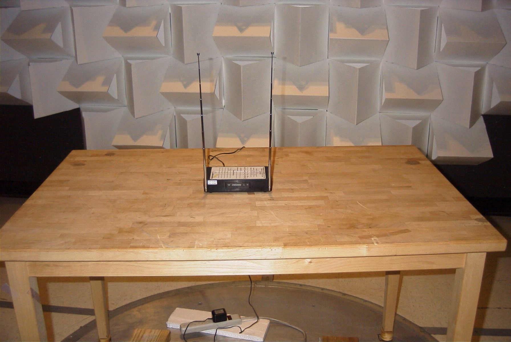
TIMCO ENGINEERING INC. 849 NW State Road 45 Newberry, Florida 32669 http://www.timcoengr.com 888.472.2424 F 352.472.2030 email: [email protected] APPLICANT: AUDIO TECHNICA CORPORATION FCC ID: JFZR250 REPORT #: V:\A\AudioTechnica_JFZ\1132UT6\1132AUT6 TestReport.doc COVER SHEET Test Report Product Name: RECEIVER FCC ID: JFZR250 Applicant: AUDIO TECHNICA CORPORATION 2206 NARUSE, MACHIDA TOKYO 194 JAPAN Date Receipt: 5/30/2006 Date Tested: 7/4/2006 TABLE OF CONTENTS LIST APPLICANT: AUDIO TECHNICA CORPORATION FCC ID: JFZR250 TIMCO ENGINEERING INC. 849 NW State Road 45 Newberry, Florida 32669 http://www.timcoengr.com 888.472.2424 F 352.472.2030 email: [email protected] APPLICANT: AUDIO TECHNICA CORPORATION FCC ID: JFZR250 REPORT #: V:\A\AudioTechnica_JFZ\1132UT6\1132AUT6 TestReport.doc TABLE OF CONTENTS TEST REPORT CONTAINING: PAGE 1 TEST EQUIPMENT LIST PAGE 2 RADIATION INTERFERENCE TEST PROCEDURES PAGE 3 RADIATION INTERFERENCE TEST DATA PAGE 4 POWER LINE CONDUCTED TEST PROCEDURE PAGE 5 POWER LINE CONDUCTED PLOT – LINE 1 PAGE 6 POWER LINE CONDUCTED PLOG – LINE 2 PAGE 7 RADIATED EMISSIONS TEST SET-UP PHOTO PAGE 8 POWERLINE CONDUCTED EMISSIONS TEST SET-UP PHOTO EXHIBITS CONTAINING: BLOCK DIAGRAM SCHEMATIC INSTRUCTION MANUAL LABEL SAMPLE LABEL LOCATION EXTERNAL PHOTOGRAPHS INTERNAL PHOTOGRAPHS TIMCO ENGINEERING INC. 849 NW State Road 45 Newberry, Florida 32669 http://www.timcoengr.com 888.472.2424 F 352.472.2030 email: [email protected] APPLICANT: AUDIO TECHNICA CORPORATION FCC ID: JFZR250 REPORT #: V:\A\AudioTechnica_JFZ\1132UT6\1132AUT6 TestReport.doc Page 1 of 8 EMC Equipment List Device Manufacturer Model Serial Number Cal/Char Date Due Date 3/10-Meter OATS TEI N/A N/A Listed 3/27/04 3/26/07 3-Meter OATS TEI N/A N/A Listed 1/11/06 1/10/09 Antenna: Biconnical Eaton 94455-1 1057 CAL 12/12/05 12/12/07 Antenna: Biconnical Eaton 94455-1 1096 CAL 8/17/04 8/17/06 Antenna: Biconnical Electro- Metrics BIA-25 1171 CAL 4/29/05 4/29/07 Analyzer Blue Tower Quasi-Peak Adapter HP 85650A 2811A01279 CAL 4/13/05 4/13/07 Analyzer Blue Tower RF Preselector HP 85685A 2926A00983 CAL 9/5/05 9/5/07 Analyzer Blue Tower Spectrum Analyzer HP 8568B 2928A04729 2848A18049 CAL 4/13/05 4/13/07 LISN Electro- Metrics ANS-25/2 2604 CAL 8/27/04 8/27/06 LISN Electro- Metrics EM-7820 2682 CAL 4/28/05 4/28/07 Antenna: Log- Periodic Eaton 96005 1243 CAL 12/14/05 12/14/07 TIMCO ENGINEERING INC. 849 NW State Road 45 Newberry, Florida 32669 http://www.timcoengr.com 888.472.2424 F 352.472.2030 email: [email protected] APPLICANT: AUDIO TECHNICA CORPORATION FCC ID: JFZR250 REPORT #: V:\A\AudioTechnica_JFZ\1132UT6\1132AUT6 TestReport.doc Page 2 of 8 TEST PROCEDURE GENERAL: This report shall NOT be reproduced except in full without the written approval of TIMCO ENGINEERING, INC. RADIATION INTERFERENCE: The test procedure used was ANSI STANDARD C63.4-2003 using a HEWLETT PACKARD spectrum analyzer with a preselector. The bandwidth of the spectrum analyzer was 100 kHZ with an appropriate sweep speed. The analyzer was calibrated in dB above a microvolt at the output of the antenna. The resolution bandwidth was 100KHZ and the video bandwidth was 300KHZ. The ambient temperature of the UUT was 80ºF with a humidity of 70%. FORMULA OF CONVERSION FACTORS: The Field Strength at 3m was established by adding the meter reading of the spectrum analyzer (which is set to read in units of dBuV) to the antenna correction factor supplied by the antenna manufacturer. The antenna correction factors are stated in terms of dB. The gain of the preselector was accounted for in the Spectrum Analyzer Meter Reading. Example: Freq (MHz) METER READING + ACF = FS 33 20 dBuV + 10.36 dB = 30.36 dBuV/m @ 3m ANSI STANDARD C63.4-2003 10.1.7 MEASUREMENT PROCEDURES: The unit under test was placed on a table 80 cm high and with dimensions of 1m by 1.5m. The table used for radiated measurements is capable of continuous rotation. When an emission was found, the table was rotated to produce the maximum signal strength. At this point, the antenna was raised and lowered from 1m to 4m. The antenna was placed in both the horizontal and vertical planes. The situation was similar for the conducted measurement except that the table did not rotate. The EUT was setup as described in ANSIC63.4-2003 with the EUT 40 cm from the vertical ground wall. TIMCO ENGINEERING INC. 849 NW State Road 45 Newberry, Florida 32669 http://www.timcoengr.com 888.472.2424 F 352.472.2030 email: [email protected] APPLICANT: AUDIO TECHNICA CORPORATION FCC ID: JFZR250 REPORT #: V:\A\AudioTechnica_JFZ\1132UT6\1132AUT6 TestReport.doc Page 3 of 8 APPLICANT: AUDIO TECHNICA CORPORATION FCC ID: JFZR250 NAME OF TEST: RADIATION INTERFERENCE RULES PART NO.: 15.109 REQUIREMENTS: 30 to 88 MHz: 40.0 dBuV/M @ 3 METERS 88 to 216 MHz: 43.5 dBuV/M 216 to 960 MHz: 46.0 dBuV/M ABOVE 960 MHz: 54.0 dBuV/M TEST RESULTS: A search was made of the spectrum from 30 to 1000MHz and the measurements indicate that the unit DOES meet the FCC requirements. TEST DATA: Tuned Frequency MHz Emission Frequency MHz Meter Reading dBuV Ant. Polarity Coax Loss dB Correction Factor dB Field Strength dBuV/m Margin dB 169.5 180.20 21.9 V 0.82 17.30 40.02 3.48 169.5 180.20 25.8 H 0.82 16.62 43.24 0.26 169.5 360.40 6.7 V 1.16 14.81 22.67 23.33 170.2 180.90 13.1 V 0.82 17.30 31.22 12.28 170.2 180.90 18.3 H 0.82 16.69 35.81 7.69 170.2 361.80 8.2 V 1.16 14.85 24.21 21.79 171.9 182.60 13.2 V 0.83 17.30 31.33 12.17 171.9 182.60 17.3 H 0.83 16.86 34.99 8.51 171.9 365.20 7.3 V 1.17 14.96 23.43 22.57 SAMPLE CALCULATION: FSdBuV/m = MR (dBuV) + ACFdB. TEST PROCEDURE: ANSI STANDARD C63.4-2003. The bandwidth of spectrum analyzer was 100 kHz with an appropriate sweep speed. When an emission was found, the table was rotated to produce the maximum signal strength. The antenna was placed in both the horizontal and vertical planes and the worse case emissions were reported. PERFORMED BY: RICHARD BLOCK DATE: 7/4/06 TIMCO ENGINEERING INC. 849 NW State Road 45 Newberry, Florida 3…
Text truncated - open the document above for the full version.
Contact Information
Applicant
Fumio Kamimura(General Manager, Engineering Planning Division)
Test Firm
Timco Engineering, Inc.Sid Sanders
Technical Specifications
| # | Rule Parts | Frequency Range | Power Output |
|---|---|---|---|
| 1 | 15B | 169 MHz - 172 MHz | - |
Other Applications from Audio-Technica Corporation
JFZDT3207DF2
Apr 06, 2026DESK STAND TRANSMITTER
Equipment Class
DWM - Part 15 Wireless MicrophoneJFZT210CS
Jul 17, 2024UniPak Transmitter
Equipment Class
TLD - Licensed LPAS DeviceJFZT220CS
Jul 17, 2024Handheld Transmitter
Equipment Class
TLD - Licensed LPAS DeviceJFZCKS50TW2R
Jun 10, 2024Wireless Headphones
Equipment Class
DTS - Digital Transmission SystemJFZCKS30TWPR
Apr 02, 2024Wireless Headphones
Equipment Class
DSS - Part 15 Spread Spectrum Transmitter