JFZR310CCOMMUNICATIONS RECEIVER
Audio-Technica Corporation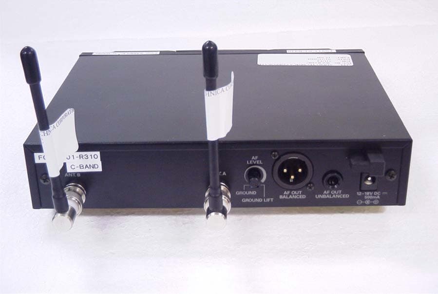
Click to zoom
Application Details
- Equipment Class
- CXX - Communications Rcvr for use w/ licensed Tx and CBs
- Date of Grant
- Feb 25, 2004
- Application Purpose
- Original Equipment
- Date of Application
- Feb 25, 2004
- Equipment Note
- COMMUNICATIONS RECEIVER
- Frequency Range
- 541.50000000 - 566.37500000
- Company
- Audio-Technica Corporation
- Country
- Japan
Documents & Files
Document Text
Text extracted from the exhibit documents filed with the FCC. Open a document above to read the original.
Users Manual
AUDIO TECHNICA MODEL ATW-3000 UHF WIRELESS MICROPHONE SYSTEM USER INFORMATION. INTRODUCTION Thank you for purchasing the ATW-3000 series wireless microphone system. It is our hope that the system will bring you years of trouble free pleasure and performance. Please follow the information contained in this manual closely as it will assist you in using your equipment effectively. PART1. REGULATORY REQUIREMENTS. FCC PART 15 COMPLIANCE STATEMENT CANADA RSS-210 COMPLIANCE STATEMENT “This device complies with Part 15 of the FCC rules. Operation is subject to the condition that this device does not cause harmful interference” “This device complies with INDUSTRY CANADA R.S.S. 210, en confomite avec IC: RSS-210/CNR210. Operation is subject to the following conditions: (1) This device may not cause harmful interference and (2) This device must accept any interference received, including interference which may cause undesired operation.” NOTE: The manufacturer is not responsible for any radio or TV interference caused by unauthorized modifications to this equipment. Such modifications could void the user’s authority to operate this equipment. Please note that your ATW-30000 system operates in a frequency band in a way which may make its use subject to certain FCC and other regulatory agency restrictions and licensing requirements. For further information, Please contact your local office of the FCC as applicable. PART 2. USING THE ATW-T310 BELTPACK TRANSMITTER The beltpack transmitter operates on 2 “AA” batteries. Please make sure that your batteries are fresh. We recommend that you use Alkaline batteries and that you avoid using NiCad if possible. Open the battery door by slide door lock towards arrow direction and lift door. Insert the batteries into the battery compartment and close the battery door Slides the LCD set up buttons cover down to bottom Push and hold the power switch and turn the ATW-T310 on Push the set button once Using up or down arrow buttons and scrolls the menu until frequency menu appeared. If current frequency setup appeared on the LCD is not the same as corresponding receiver frequency, push set button once. Push down or up arrow button and set frequency to the corresponding frequency as set on receiver. Push and hold set button until word “Stored” displayed in a while. Push up or down arrow button and scrolls the menu until input menu (MIC or INSTRUMENT) appeared. If current input setup appeared on LCD screen is not correct, push set button once Using up or down arrow button to select input. Push and hold set button until word “Stored” displayed in a while. Connect your microphone or guitar cable to the connector on the top side of the transmitter. \ Confirm that the receiver is receiving RF and the audio is passing through the receiver. Push up or down arrow button and scrolls the menu until “ESCAPE” appeared Push the set button once to return default menu You are now set to use the system. PART 3. USING THE ATW-T341 HANDHELD TRANSMITTER The handheld transmitter operates on 2 “AA” batteries. Please make sure that your batteries are fresh. We recommend that you use Alkaline batteries and that you avoid using NiCad if possible. Hold the bottom grip and turn the top grip counter clockwise until bottom grip free to slide. Slide the bottom grip, insert the batteries into the battery compartment and slide the battery compartment back into place. To change the frequency of operation, push and hold power /mute button located on bottom of transmitter to turn it on. Unscrew the battery cover and pull the cover back. Push the set button once Using up or down arrow button and scrolls the menu until frequency menu appeared. Push the set button once. Push down or up arrow button and set frequency to the corresponding frequency as set on receiver. Push and hold set button until word “Stored” displayed in a while. Push up or down arrow button and scrolls the menu until “ESCAPE” appeared Push the set button once to return default menu You are now set to use the system. PART4. USING THE ATW-R310 RECEIVER Connect the AC adapter DC output connector to The ATW-R310 DC input jack Plug the 2 blades AC plug on AC adaptor AC cable to an 110V AC outlet. Push the on off switch. Confirm that the backlight on LCD screen comes on. Check the frequency setting to confirm that they correspond to the settings of the transmitter If not, push and hold set button until frequency only displayed on LCD Push set button once and check that frequency displayed on LCD brink. Push up or down arrow button to set receiver frequency to corresponding transmitter frequency. Pus set button once to set frequency. Push up or down arrow buttons to scrolls menu until VR and percent figures appeared If it not set to the VR 100%, push set button once and check that item displayed on LCD brink Push up arrow button to set it to maximum. Push set button once to set Push and hold Set button until LCD displayed “DEF” in a while Connect the balanced or unbalanced audio output to your mixer or PA system. Adjust the Volume setting to the desired level. Speak into the microphone and listen to the audio out at the speaker. If satisfied with the audio quality, you ca use the system.
Cover Letter(s)
Audio-Technica U.S., Inc. 1221 Commerce Drive Phone: 330-686-2600 [email protected] Stow, OH 44224-1760 Fax: 330-688-3752 January 15, 2004 Equipment Authorization Division Office of Engineering and Technology Federal Communications Commission 7435 Oakland Mills Road Columbia, MD 21046 Ref: FCC ID: JFZR310C Request for Confidentiality Dear Sirs: With regard to the referenced application, Audio Technica., is requesting confidentiality of certain sections of the accompanying documents. The documents for which Audio Technica is requesting confidentiality are: Schematic for ATW-R310C wireless receiver Block diagram for ATW-R310C wireless receiver Circuit description for ATW-R310C wireless receiver This request is made under the provisions of Section 0.457(d) of the Commission’s Rules, and Section 552(b)(4) of the Freedom of Information Act. The material for which confidentiality is requested falls within the scope of Section 552(b)(4) as trade secrets and includes material covered by Section 0.459 of the Commission’s Rules. Sincerely, Jacquelynn Green Vice President R&D Audio-Technica U.S., Inc.
Test Report
TIMCO ENGINEERING INC. 849 NW State Road 45 Newberry, Florida 32669 http://www.timcoengr.com 888.472.2424 F 352.472.2030 email: [email protected] APPLICANT: AUDIO TECHNICA CORPORATION FCC ID: JFZR310C REPORT #: A\AudioTechnica_JFZ\71UT4\71UT4TestReport.doc COVER SHEET Test Report Product Name: COMMUNICATIONS RECEIVER FCC ID: JFZR310C Applicant: AUDIO TECHNICA CORPORATION 2206 NARUSE, MACHIDA TOKYO 194 JAPAN Date Receipt: JANUARY 21, 2004 Date Tested: FEBRUARY 9, 2004 TIMCO ENGINEERING INC. 849 NW State Road 45 Newberry, Florida 32669 http://www.timcoengr.com 888.472.2424 F 352.472.2030 email: [email protected] APPLICANT: AUDIO TECHNICA CORPORATION FCC ID: JFZR310C REPORT #: A\AudioTechnica_JFZ\71UT4\71UT4TestReport.doc TABLE OF CONTENTS APPLICANT: AUDIO TECHNICA CORPORATION FCC ID: JFZR310C TABLE OF CONTENTS LIST TEST REPORT CONTAINING: PAGE 1...............TEST EQUIPMENT LIST PAGE 2...............TEST PROCEDURES PAGE 3...............RADIATION INTERFERENCE TEST DATA PAGE 4...............POWER LINE CONDUCTED EMISSIONS PAGE 5...............POWER LINE CONDUCTED PLOTS EXHIBITS CONTAINING: CONFIDENTIALITY LETTER BLOCK DIAGRAM SCHEMATIC USERS MANUAL LABEL SAMPLE LABEL LOCATION EXTERNAL PHOTOGRAPHS INTERNAL PHOTOGRAPHS CIRCUIT DESCRIPTION TEST SET UP PHOTOGRAPH TIMCO ENGINEERING INC. 849 NW State Road 45 Newberry, Florida 32669 http://www.timcoengr.com 888.472.2424 F 352.472.2030 email: [email protected] APPLICANT: AUDIO TECHNICA CORPORATION FCC ID: JFZR310C REPORT #: A\AudioTechnica_JFZ\71UT4\71UT4TestReport.doc Page 1 of 5 EMC Equipment List Device Manufacturer Model Serial Number Cal/Char Date Due Date 3/10-Meter OATS TEI N/A N/A Listed 3/26/01 3/26/04 3-Meter OATS TEI N/A N/A Listed 1/13/03 1/13/06 Biconnical Antenna Eaton 94455-1 1057 CAL 3/18/03 3/18/05 Biconnical Antenna Eaton 94455-1 1096 CAL 10/1/01 10/1/03 Biconnical Antenna Electro- Metrics BIA-25 1171 CAL 4/26/01 4/26/03 Blue Tower Quasi-Peak Adapter HP 85650A 2811A01279 CAL 4/15/03 4/15/05 Blue Tower RF Preselector HP 85685A 2926A00983 CAL 4/15/03 4/15/05 Blue Tower Spectrum Analyzer HP 8568B 2928A04729 2848A18049 CAL 4/15/03 4/15/05 LISN Electro- Metrics ANS-25/2 2604 CAL 10/9/01 10/9/03 LISN Electro- Metrics EM-7820 2682 CAL 3/12/03 3/12/05 Log- Periodic Antenna Eaton 96005 1243 CAL 5/8/03 5/8/05 TIMCO ENGINEERING INC. 849 NW State Road 45 Newberry, Florida 32669 http://www.timcoengr.com 888.472.2424 F 352.472.2030 email: [email protected] APPLICANT: AUDIO TECHNICA CORPORATION FCC ID: JFZR310C REPORT #: A\AudioTechnica_JFZ\71UT4\71UT4TestReport.doc Page 2 of 5 TEST PROCEDURE GENERAL: This report shall NOT be reproduced except in full without the written approval of TIMCO ENGINEERING, INC. RADIATION INTERFERENCE: The test procedure used was ANSI STANDARD C63.4-2001 using a HEWLETT PACKARD spectrum analyzer with a preselector. The bandwidth of the spectrum analyzer was 100 kHZ with an appropriate sweep speed. The analyzer was calibrated in dB above a microvolt at the output of the antenna. The resolution bandwidth was 100KHZ and the video bandwidth was 300KHZ. The ambient temperature of the UUT was 65ºF with a humidity of 70%. FORMULA OF CONVERSION FACTORS: The Field Strength at 3m was established by adding the meter reading of the spectrum analyzer (which is set to read in units of dBuV) to the antenna correction factor supplied by the antenna manufacturer. The antenna correction factors are stated in terms of dB. The gain of the Preselector was accounted for in the Spectrum Analyzer Meter Reading. Example: Freq (MHz) METER READING + ACF = FS 33 20 dBuV + 10.36 dB = 30.36 dBuV/m @ 3m ANSI STANDARD C63.4-2001 10.1.7 MEASUREMENT PROCEDURES: The unit under test was placed on a table 80 cm high and with dimensions of 1m by 1.5m. The table used for radiated measurements is capable of continuous rotation. When an emission was found, the table was rotated to produce the maximum signal strength. At this point, the antenna was raised and lowered from 1m to 4m and measured to the 10th harmonic. The antenna was placed in both the horizontal and vertical planes. The situation was similar for the conducted measurement except that the table did not rotate. The EUT was setup as described in ANSIC63.4-1992 with the EUT 40 cm from the vertical ground wall. TIMCO ENGINEERING INC. 849 NW State Road 45 Newberry, Florida 32669 http://www.timcoengr.com 888.472.2424 F 352.472.2030 email: [email protected] APPLICANT: AUDIO TECHNICA CORPORATION FCC ID: JFZR310C REPORT #: A\AudioTechnica_JFZ\71UT4\71UT4TestReport.doc Page 3 of 5 APPLICANT: AUDIO TECHNICA CORPORATION FCC ID: JFZR310C NAME OF TEST: RADIATION INTERFERENCE RULES PART NO.: 15.109 REQUIREMENTS: 30 to 88 MHz: 40.0 dBuV/M @ 3 METERS 88 to 216 MHz: 43.5 dBuV/M 216 to 960 MHz: 46.0 dBuV/M ABOVE 960 MHz: 54.0 dBuV/M TEST RESULTS: A search was made of the spectrum from 30 to 1000MHz and the measurements indicate that the unit DOES meet the FCC requirements. TEST DATA: Tuned Frequency MHz Emission Frequency MHz Meter Reading dBuV Ant. Polarity Coax Loss dB Correction Factor dB Field Strength dBuV/m Margin dB 541.5 456.17 11.2 V 2.97 17.57 31.74 14.26 541.5 456.17 11.5 H 2.97 18.03 32.50 13.50 541.5 912.30 10.1 V 3.83 23.59 37.52 8.48 541.5 912.30 11.1 H 3.83 24.01 38.94 7.06 541.5 1,368.43 20.5 V 1.38 26.45 48.33 5.67 541.5 1,368.43 22.2 H 1.38 26.45 50.03 3.97 553.9 468.56 12.1 V 3.01 17.00 32.11 13.89 553.9 468.56 12.2 H 3.01 17.56 32.77 13.23 553.9 937.05 11.2 H 3.09 26.88 41.17 4.83 553.9 937.05 11.3 V 3.09 25.45 39.84 6.16 553.9 1,405.55 19.6 V 1.40 26.58 47.58 6.42 553.9 1,405.55 21.1 H 1.40 26.58 49.08 4.92 566.4 481.03 11.7 H 3.04 18.24 32.98 13.02 566.4 481.03 12.3 V 3.04 17.45 32.79 13.21 566.4 962.06 10.5 V 2.34 23.56 36.40 17.60 566.4 962.06 11.6 H 2.34 24.30 38.24 15.76 566.4 1,443.09 19.8 V 1.42 26.71 47.93 6.07 566.4 1,443.09 20.4 H 1.42 26.71 48.53 5.47 SAMPLE CALCULATION: FSdBuV/m = MR (dBuV) + ACFdB. TEST PROCEDURE: ANSI STANDARD C63.4-2001 using a Hewlett Packard Model 8566B spectrum…
Text truncated - open the document above for the full version.
Contact Information
Applicant
Fumio Kamimura(General Manager, Engineering Planning Division)
Test Firm
Timco Engineering, Inc.S Sanders
Technical Specifications
| # | Rule Parts | Frequency Range | Power Output |
|---|---|---|---|
| 1 | 15B | 541.5 MHz - 566.375 MHz | - |
Other Applications from Audio-Technica Corporation
JFZDT3207DF2
Apr 06, 2026DESK STAND TRANSMITTER
Equipment Class
DWM - Part 15 Wireless MicrophoneJFZT210CS
Jul 17, 2024UniPak Transmitter
Equipment Class
TLD - Licensed LPAS DeviceJFZT220CS
Jul 17, 2024Handheld Transmitter
Equipment Class
TLD - Licensed LPAS DeviceJFZCKS50TW2R
Jun 10, 2024Wireless Headphones
Equipment Class
DTS - Digital Transmission SystemJFZCKS30TWPR
Apr 02, 2024Wireless Headphones
Equipment Class
DSS - Part 15 Spread Spectrum Transmitter