JFZR5200DCommunications Receiver
Audio-Technica Corporation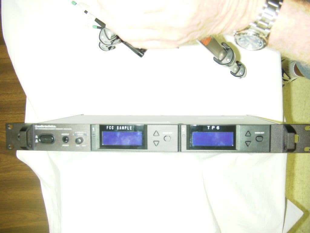
Click to zoom
Application Details
- Equipment Class
- CXX - Communications Rcvr for use w/ licensed Tx and CBs
- Date of Grant
- Aug 08, 2002
- Application Purpose
- Original Equipment
- Date of Application
- Aug 08, 2002
- Equipment Note
- Communications Receiver
- Frequency Range
- 655.00000000 - 681.00000000
- Company
- Audio-Technica Corporation
- Country
- Japan
Documents & Files
Document Text
Text extracted from the exhibit documents filed with the FCC. Open a document above to read the original.
Users Manual
AUDIO TECHNICA MODEL AEW-5200, AEW-4100 SERIES UHF WIRELESS SYSTEM USER INFORMATION. INTRODUCTION Thank you for purchasing the AEW-5200, AEW4100 series wireless system. It is our hope that the system will bring you years of trouble free pleasure and performance. Please follow the information contained in this manual closely as it will assist you in using your equipment effectively. PART1. REGULATORY REQUIREMENTS. FCC PART 15 COMPLIANCE STATEMENT CANADA RSS-210 COMPLIANCE STATEMENT “This device complies with Part 15 of the FCC rules. Operation is subject to the condition that this device does not cause harmful interference” “This device complies with INDUSTRY CANADA R.S.S. 210, en confomite avec IC: RSS-210/CNR210. Operation is subject to the following conditions: (1) This device may not cause harmful interference and (2) This device must accept any interference received, including interference which may cause undesired operation.” Please note that your AEW-5200, AEW4100 systems operates in a frequency band in a way which may make its use subject to certain FCC and other regulatory agency restrictions and licensing requirements. For further information, Please contact your local office of the FCC as applicable. NOTE: THE MANUFACTURER IS NOT RESPONSIBLE FOR ANY RADIO OR TV INTERFERENCE CAUSED BY UNAUTHORIZED MODIFICATIONS TO THIS EQUIPMENT. SUCH MODIFICATIONS COULD VOID THE USER'S AUTHORITY TO OPERATE THE EQUIPMENT. PART 2. USING THE AEW-T1000 BELTPACK TRANSMITTER The beltpack transmitter operates on 2 “AA” batteries. Please make sure that your batteries are fresh. We recommend that you use Alkaline batteries and that you avoid using NiCad if possible. Open the battery door by slide door lock towards arrow direction and lift door. Insert two batteries into the battery compartment and close the battery door Slides the LCD set up buttons cover down to bottom Push and hold the power switch and turn the AEW-T1000 on Push the set button once Using up or down arrow buttons and scrolls the menu until frequency menu appeared. If current frequency setup appeared on the LCD is not the same as corresponding receiver frequency, push set button once. Push down or up arrow button and set frequency to the corresponding frequency as set on receiver. Push and hold set button until word “Stored” displayed in a while. Push up or down arrow button and scrolls the menu until input menu (MIC or INSTRUMENT) appeared. If current input setup appeared on LCD screen is not correct, push set button once Using up or down arrow button to select input. Push and hold set button until word “Stored” displayed in a while. Connect your microphone or guitar cable to the connector on the top of the transmitter. Confirm that the receiver is receiving RF and the audio is passing through the receiver. Push up or down arrow button and scrolls the menu until “ESCAPE” appeared. Push the set button once to return default menu. You are now ready to use the system. PART 3. USING THE AEW-T5000SERIES HANDHELD TRANSMITTER AEW-T5000 transmitter family is as follows: AEW-T5400 AEW-T3300 AEW-T6100 AEW-T4100 The handheld transmitter operates on 2 “AA” batteries. Please make sure that your batteries are fresh. We recommend that you use Alkaline batteries and that you avoid using NiCad if possible. Hold the bottom grip and turn the top grip counter clockwise until bottom grip free to slide. Slide the bottom grip, insert two batteries into the battery compartment and slide the battery compartment back into place. To change the frequency of operation, push and hold the power /mute button located on bottom of the transmitter to turn it on. Unscrew the battery cover and pull the cover back. Push the set button once Using up or down arrow button and scrolls the menu until frequency menu appeared. Push the set button once. Push down or up arrow button and set frequency to the corresponding frequency as set on receiver. Push and hold set button until word “Stored” displayed in a while. Push up or down arrow button and scrolls the menu until “ESCAPE” appeared Push the set button once to return default menu You are now set to use the system. PART4. USING THE AEW-R5200, AEW-R4100 RECEIVERS Plug the IEC plug on the AC cable to the AC inlet on back of the receiver. Plug the 3-pin AC plug on AC cable to an 110V AC outlet. Connect two antennas to the antenna input on back of the receiver. Push the Power switch. Confirm that the backlight on LCD screen comes on. Check the frequency setting to confirm that they correspond to the settings of the transmitter If not, push set button once to display “FREQ” on top line of the LCD. Push set button once and check that “EDIT” displayed on bottom line of LCD brink. Push up or down arrow button to set receiver frequency to corresponding transmitter frequency. Push and hold set button until “STORED” displayed in a while. Push up or down arrow button to display “QUIT” Push Set button once to back in to Default menu. Connect the balanced or unbalanced audio output to your mixer or PA system. Adjust the Volume setting to the desired level. Speak into the microphone and listen to the audio out at the speaker. If satisfied with the audio quality, you ca uses the system.
Test Report
APPLICANT: AUDIO TECHNICA CORPORATION FCC ID: JFZR5200D REPORT #: T:\A\AudioTechnica_JFZ\741UT2\741UT2TestReport.doc TABLE OF CONTENTS LIST TABLE OF CONTENTS LIST APPLICANT: AUDIO TECHNICA CORPORATION FCC ID: JFZR5200D TEST REPORT CONTAINING: PAGE 1-4....TEST EQUIPMENT LIST PAGE 5......TEST PROCEDURES PAGE 6......RADIATION INTERFERENCE TEST DATA PAGE 7-9....POWERLINE CONDUCTED INTERFERENCE EXHIBITS CONTAINING: EXHIBIT 1............BLOCK DIAGRAM EXHIBIT 2............SCHEMATIC EXHIBIT 3............INSTRUCTION MANUAL EXHIBIT 4............LABEL SAMPLE AND LOCATION EXHIBIT 5............EXTERNAL PHOTO - FRONT SIDE EXHIBIT 6............EXTERNAL PHOTO - BACK SIDE EXHIBIT 7............INTERNAL PHOTO - COMPONENT SIDE EXHIBIT 8............INTERNAL PHOTO - COPPER SIDE EXHIBIT 9............CIRCUIT DESCRIPTION EXHIBIT 10...........TEST SET UP PHOTO APPLICANT: AUDIO TECHNICA CORPORATION FCC ID: JFZR5200D REPORT #: T:\A\AudioTechnica_JFZ\741UT2\741UT2TestReport.doc Page 1 of 9 Equipment List DEVICE MFGR MODEL SERNO CAL/CHAR DATE DUE DATE or STATUS X 3-Meter OATS TEI N/A N/A Listed 12/22/99 12/22/02 3/10-Meter OATS TEI N/A N/A Listed 3/26/01 3/26/04 X Receiver, Beige Tower X Spectrum Analyzer (Tan) HP 8566B Opt 462 3138A07786 3144A20661 CAL 8/31/01 8/31/02 X RF Preselector (Tan) HP 85685A 3221A01400 CAL 8/31/01 8/31/02 X Quasi-Peak Adapter (Tan) HP 85650A 3303A01690 CAL 8/31/01 8/31/02 Receiver, Blue Tower Spectrum Analyzer (Blue) HP 8568B 2928A04729 2848A18049 CHAR 10/22/01 10/22/02 RF Preselector (Blue) HP 85685A 2926A00983 CHAR 10/22/01 10/22/02 Quasi-Peak Adapter (Blue) HP 85650A 2811A01279 CHAR 10/22/01 10/22/02 Biconnical Antenna Electro-Metrics BIA-25 1171 CAL 4/26/01 4/26/03 X Biconnical Antenna Eaton 94455-1 1096 CAL 10/1/01 10/1/02 Biconnical Antenna Eaton 94455-1 1057 CHAR 3/15/00 3/15/01 BiconiLog Antenna EMCO 3143 9409-1043 X Log-Periodic Antenna Electro-Metrics LPA-25 1122 CAL 10/2/01 10/2/02 Log-Periodic Antenna Electro-Metrics EM-6950 632 CHAR 10/15/01 10/15/02 Log-Periodic Antenna Electro-Metrics LPA-30 409 CHAR 10/16/01 10/16/02 Dipole Antenna Kit Electro-Metrics TDA-30/1-4 152 CAL 3/21/01 3/21/02 Dipole Antenna Kit Electro-Metrics TDA-30/1-4 153 CHAR 11/24/00 11/24/01 Double-Ridged Horn Antenna Electro-Metrics RGA-180 2319 CAL 12/19/01 12/19/02 Horn Antenna Electro-Metrics EM-6961 6246 CAL 3/21/01 3/21/02 Horn Antenna ATM 19-443-6R None No Cal Required APPLICANT: AUDIO TECHNICA CORPORATION FCC ID: JFZR5200D REPORT #: T:\A\AudioTechnica_JFZ\741UT2\741UT2TestReport.doc Page 2 of 9 Passive Loop Antenna EMC Test Systems EMCO 6512 9706-1211 CHAR 7/10/01 7/10/02 Line Impedance Stabilization . . . Electro-Metrics ANS-25/2 2604 CAL 10/9/01 10/9/02 Line Impedance Stabilization . . . Electro-Metrics EM-7820 2682 CAL 3/16/01 3/16/02 Termaline Wattmeter Bird Electronic Corporation 611 16405 CAL 5/25/99 (5/25/00) Termaline Wattmeter Bird Electronic Corporation 6104 1926 CAL 12/12/01 12/12/02 Oscilloscope Tektronix 2230 300572 CHAR 2/1/01 2/1/02 Temperature Chamber Tenney Engineering TTRC 11717-7 CHAR 1/22/02 1/22/03 AC Voltmeter HP 400FL 2213A14499 CAL 10/9/01 10/9/02 AC Voltmeter HP 400FL 2213A14261 CHAR 10/15/01 10/15/02 AC Voltmeter HP 400FL 2213A14728 CHAR 10/15/01 10/15/02 Digital Multimeter Fluke 77 35053830 CHAR 1/8/02 1/8/03 Digital Multimeter Fluke 77 43850817 CHAR 1/8/02 1/8/03 Digital Multimeter HP E2377A 2927J05849 CHAR 1/8/02 1/8/03 Multimeter Fluke FLUKE-77-3 79510405 CAL 9/26/01 9/26/02 Peak Power Meter HP 8900C 2131A00545 CHAR 1/26/01 1/26/02 Digital Thermometer Fluke 2166A 42032 CAL 1/16/02 1/16/03 Thermometer Traulsen SK-128 CHAR 1/22/02 1/22/03 Temp/Humidity gauge EXTech 44577F E000901 CHAR 1/22/02 1/22/03 Frequency Counter HP 5352B 2632A00165 CAL 11/28/01 11/28/02 Power Sensor Agilent Technologies 84811A 2551A02705 CAL 1/26/01 1/26/02 Injection Probe Fischer Custom Communications F-120-9A 270 CAL 6/1/01 6/1/02 Service Monitor IFR FM/AM 500A 5182 CAL 11/22/00 11/22/01 APPLICANT: AUDIO TECHNICA CORPORATION FCC ID: JFZR5200D REPORT #: T:\A\AudioTechnica_JFZ\741UT2\741UT2TestReport.doc Page 3 of 9 Comm. Serv. Monitor IFR FM/AM 1200S 6593 CAL 11/12/99 11/12/00 Signal Generator HP 8640B 2308A21464 CAL 11/15/01 11/15/02 Modulation Analyzer HP 8901A 3435A06868 CAL 9/5/01 9/5/02 Power Line Coupling/ Decoupling Network Fischer Custom Communications FCC-801-M2- 16A 01048 CAL 8/29/01 8/29/02 Power Line Coupling/ Decoupling Network Fischer Custom Communications FCC-801-M3- 16A 01060 CAL 8/29/01 8/29/02 VHF/UHF Current Probe Fischer Custom Communications F-52 130 CAL 8/30/01 8/30/02 Passive Impedance Adapter Fischer Custom Communications FCC-801-150-50- CDN 01117 & 01118 CAL 8/29/01 8/29/02 Radiating Field Coil Fischer Custom Communications F-1000-4-8/9/10- L-1M 9859 CAL 10/15/98 10/15/99 Near Field Probe HP HP11940A 2650A02748 CHAR 2/1/01 2/1/02 BandReject Filter Lorch Microwave 5BR4-2400/ 60-N Z1 CHAR 3/2/01 3/2/02 BandReject Filter Lorch Microwave 6BR6-2442/ 300-N Z1 CHAR 3/2/01 3/2/02 BandReject Filter Lorch Microwave 5BR4-10525/ 900-S Z1 CHAR 3/2/01 3/2/02 High Pas Filter Microlab HA-10N CHAR 10/4/01 10/4/02 Audio Oscillator HP 653A 832-00260 CHAR 3/1/01 3/1/02 Frequency Counter HP 5382A 1620A03535 CHAR 3/2/01 3/2/02 Frequency Counter HP 5385A 3242A07460 CHAR 12/11/01 12/11/02 Preamplifier HP 8449B-H02 3008A00372 CHAR 3/4/01 3/4/02 Amplifier HP 11975A 2738A01969 CHAR 3/1/01 3/1/02 Egg Timer Unk CHAR 2/28/01 2/28/02 Measuring Tape, 20M Kraftixx 0631-20 CHAR 2/28/01 2/28/02 Measuring Tape, 7.5M Kraftixx 7.5M PROFI CHAR 2/28/01 2/28/02 EMC Immunity Test System Keytek CEMASTER 9810210 AC Power Source California Instruments 1251RP L05865 APPLICANT: AUDIO TECHNICA CORPORATION FCC ID: JFZR5200D REPORT #: T:\A\AudioTechnica_JFZ\741UT2\741UT2TestReport.doc Page 4 of 9 AC Power Source California Instruments PACS-1 X71484 Isotropic Field Probe Amplifier Research FP5000 22839 Isotropic Field Probe Amplifier Research FP5000 300103 Capacitor Clamp Keytek CM-CCL 9811359 No Cal Required Amplifier Amplif…
Text truncated - open the document above for the full version.
Test Setup Photos
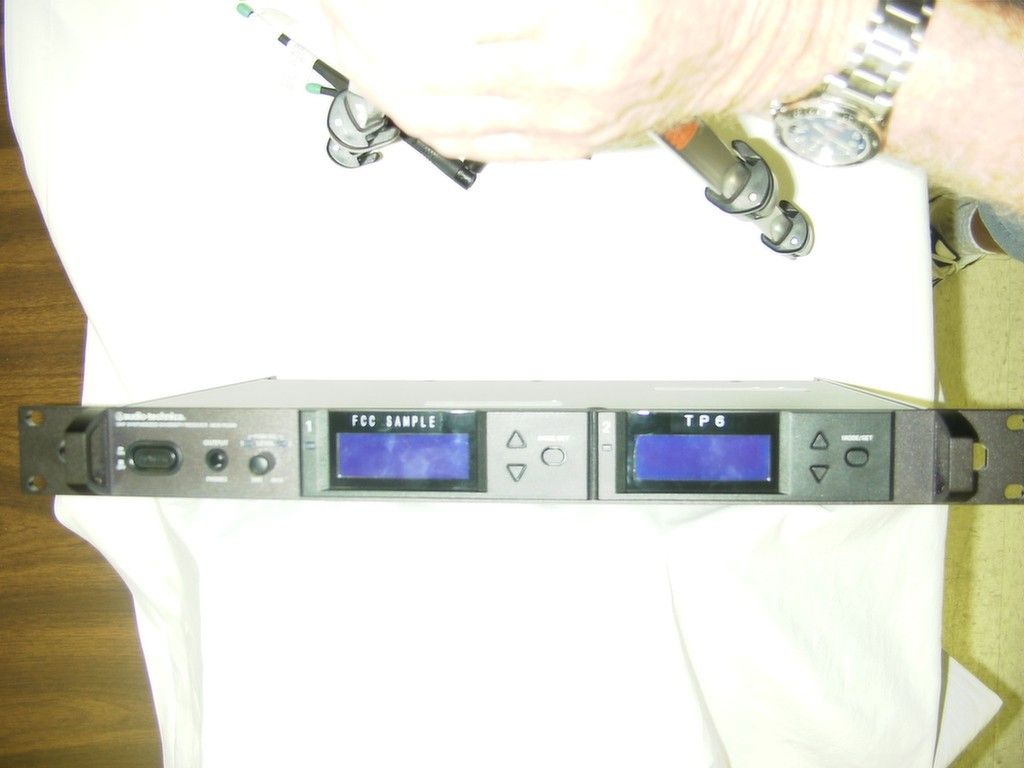
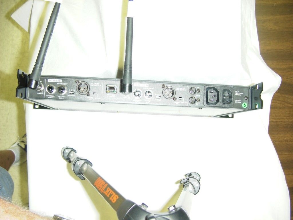
RADIATED TEST SET UP PHOTOGRAPH POWERLINE CONDUCTED EMISSIONS TEST SET UP PHOTO
Contact Information
Applicant
Fumio Kamimura(General Manager, Engineering Planning Division)
Test Firm
Timco Engineering, Inc.S Sanders
Technical Specifications
| # | Rule Parts | Frequency Range | Power Output |
|---|---|---|---|
| 1 | 15B | 655 MHz - 681 MHz | - |
Other Applications from Audio-Technica Corporation
JFZDT3207DF2
Apr 06, 2026DESK STAND TRANSMITTER
Equipment Class
DWM - Part 15 Wireless MicrophoneJFZT210CS
Jul 17, 2024UniPak Transmitter
Equipment Class
TLD - Licensed LPAS DeviceJFZT220CS
Jul 17, 2024Handheld Transmitter
Equipment Class
TLD - Licensed LPAS DeviceJFZCKS50TW2R
Jun 10, 2024Wireless Headphones
Equipment Class
DTS - Digital Transmission SystemJFZCKS30TWPR
Apr 02, 2024Wireless Headphones
Equipment Class
DSS - Part 15 Spread Spectrum Transmitter