JFZRP32Studio Broadcast UWB Wireless Microphone System
Audio-Technica Corporation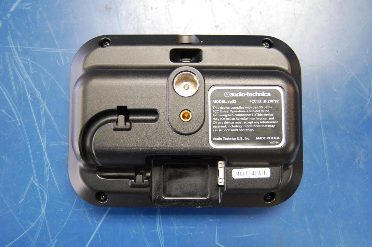
Click to zoom
Application Details
- Equipment Class
- UWB - Ultra Wideband Transmitter
- Date of Grant
- Dec 02, 2015
- Application Purpose
- Original Equipment
- Date of Application
- Dec 02, 2015
- Equipment Note
- Studio Broadcast UWB Wireless Microphone System
- Frequency Range
- 5825.60000000 - 6731.20000000
- Company
- Audio-Technica Corporation
- Country
- Japan
Documents & Files
Document Text
Text extracted from the exhibit documents filed with the FCC. Open a document above to read the original.
Users Manual
Studio Broadcast System SET UP and USE Studio Broadcast System Page 2 of 26 1. REGULATORY AND COMPLIANCE STATEMENTS ............................................................................................................ 3 2. OVERVIEW 2.1 Core Performance Targets 2.2 Specifications 2.3 System Components 2.4 System Block Diagram 3. BP24 UWB BODY PACK TRANSMITTER ........................................................................................................................... 4. RP32 UWB RECEIVER MODULE ....................................................................................................................................... 5. MCU3224 MAIN CONTROL UNIT ..................................................................................................................................... 4.1. FRONT PANEL ........................................................................................................................................................................................... 4.2. REAR PANEL ............................................................................................................................................................................................. 6. GUI INTERFACE ............................................................................................................................................................... 5.1. HOME SCREEN .......................................................................................................................................................................................... 5.2. TRANSMITTER DETAIL SCREEN ...................................................................................................................................................................... 5.3. MATRIX SCREEN - RECEIVER MEASUREMENT ................................................................................................................................................... 5.4. MATRIX SCREEN – TRANSMITTER MEASUREMENT ............................................................................................................................................. 5.5. SETUP SCREEN .......................................................................................................................................................................................... 7. QUICK START ............................................................................................................................................................... Studio Broadcast System Page 3 of 26 1. REGULATORY AND COMPLIANCE Studio Broadcast System Page 4 of 26 2. Overview 2.1 Core Performance Targets STUDIO BROADCAST Operating Method UWB OOK Center frequency 6.500GHz Simultaneous Receive Points 32 Simultaneous Transmitters 24 Audio Dynamic Range 24 bits Frequency Response 20Hz -20kHz Latency <3 mS Analog to Digital out Audio Interface MADI/DANTE External Control Interface USB/Ethernet User Interface Touchscreen GUI Battery Life 5 hours Range (single RP line of sight) 90 feet Studio Broadcast System Page 5 of 26 2.2 Specifications Overall System Dynamic Range >109 dB (A-weighted, typical) Total Harmonic Distortion <0.06% (-40dBV input level) BP24 Specs (inherent to beltpack / Direct connect Self Noise @ 0dB gain -111dBA Self Noise @ 20dB gain -106dBA Sensitivity @ 0dB gain -44dBV Sensitivity @ 20dB gain -23dBV Dynamic Range 111dB (A-weighted, typical) SNR @ 0dB gain 67dBA SNR @ 20 dB gain 82dBA Maximum Input Level (5% THD) 4.8dBV Total Harmonic Distortion <0.06% (-40dBV input level) Operating Frequency Range 6250MHz – 6750MHz Tx Output Power 2nW mean Modulation none Emissions Designator 500MN1W Studio Broadcast System Page 6 of 26 BP24 w/ AT899cL4 or cL4SW mic Self-Noise @ 0dB gain -109dBA Self-Noise @ 20dB gain -93dBA Sensitivity @ 0dB gain -48dBV Sensitivity @ 20dB gain -28dBV Dynamic Range 109dB (A-weighted, typical) SNR @ 0dB gain 61dBA SNR @ 20dB gain 65dBA Frequency Response 20Hz – 20,000Hz Impedance 250 ohms DC current 1.7mA Battery 2 x AA Battery life 5 hours MCU3224 Frequency Response 20Hz – 20,000Hz Input/Output Connections MADI 2 x 75 ohm BNC to coax, 2 x multimode fiber DANTE 2 x RJ45 Receivers 32 x 12 V, RJ45 Black burst 1 x BNC Headphone/Monitor Out @ 33 ohm load Total Harmonic Distortion <0.1% Noise -90dBV Maximum Output Power 200mW Power Redundant AC supply 2 x 110-240V, 50-50Hz, 420W max Cable 2 x IEC Studio Broadcast System Page 7 of 26 2.3 System Components Model Description BP24 Body Pack Transmitter with Talkback Function RP32 UWB Receiver and Antenna Module MCU3224 Main Control Interface Unit (3U) AT899cL4 or cL4SW Microphone Microphone with Inline Talkback Switch 2.4 System Block Diagram ` MAIN CONTROL INTERFACE UNIT (3U) TX 1 . . . TX 24 RX 1 RX 32 . . . Wireless Links (TDMA) Cat 5 - All RX Home Run to Main Control Unit . . . Mains In (Red) Mains In (Blue) Network Control (Future) Ethernet Network Audio Dante (Future) Ethernet BNC-Audio Word Clock In Word Clock Out MADI 75Ω co-ax MADI Fiber (GBIC) Fiber Out Audio CH 1-8 7” TOUCH SCREEN GUI (on-board) FUTURE Analog Break Out Box x8 Or AES 3 Outputs FUTURE Analog Break Out Box x8 Or AES 3 Outputs (Future) FUTURE Analog Break Out Box x8 Or AES 3 Outputs Dante 1 Dante 2 Audio CH 9-16 Audio CH 17-24 x24 x32 Fiber In Studio Broadcast System Page 8 of 26 3 BP24 UWB Body Pack Transmitter 3.1 Transmitter Controls An On/Off power switch is located in the battery compartment. The adjustable transmitter parameters are: 1. System ID (SYS) – Each transmitter must be assigned a system ID (1-9) that must match the system ID set on the MCU3224 The transmitter will only transmit when it receives a sync pulse and matching system ID from an active system. This will prevent users with transmitters assigned the same channel slot on a different system from interfering if they enter the coverage area. Note: RP timing signals from separate systems must be RF isolated from on…
Text truncated - open the document above for the full version.
Users Manual
Studio Broadcast System SET UP and USE RP32 Receiver Module Studio Broadcast System Page 2 of 13 1. REGULATORY AND COMPLIANCE STATEMENTS ............................................................................................................ 3 2. RP32 UWB RECEIVER MODULE ....................................................................................................................................... 3. POSITIONING AND SET UP.............................................................................................................................................................. 4. SYSTEM QUICK START ................................................................................................................................................ Studio Broadcast System Page 3 of 13 1. REGULATORY AND COMPLIANCE STATIC HAZARD. Opening this unit is likely to cause permanent performance malfunction. Evidence of opening will void warranty. Serviceable only by Audio- Technica. Contact Audio-Technica for return authorization should service be necessary Studio Broadcast System Page 4 of 13 2. RP32 UWB Receiver Module A two digit display (7 Segment LED) is provided to automatically indicate the receiver channel number when the RP32 is connected via a CAT5 cable to the corresponding output channel of the MCU3224. This display serves as the unit’s power indicator. A visible channel number also indicates that there is a full round-trip connection between the RP and the MCU communications, confirming that the cable, the RP and the corresponding MCU3224 channel are all operating appropriately. Should the user prefer that the LED lights not be illuminated, there is a control option available on the MCU “tools” screen which allows this RP display lights to be turned off. Receiver ID Number Receiver Front View Studio Broadcast System Page 5 of 13 Receiver Rear View RJ45 Connector for Cat5 Cable Connection to the RP32 is via an RJ45 jack on the rear. Once connected via RJ45 and shielded CAT5 cable to an MCU, the RP is operational. There is no power switch, and no further controls necessary. The MCU3224 supplies operating power and control over RP functions/preferences is available via the tools screen of the MCU3224. A choice of 2 mounting threads are available on the rear of the RP32. The inserts mate with either 5/8”-27 thread or ¼”-20 thread adapters. Studio Broadcast System Page 6 of 13 3. Positioning and Set Up 3.1. Positioning When considering where to place RP32 Receiver Modules, it is useful to think of them as “lights” with which you are attempting to cover and entirely fill a space. A rough guideline of coverage pattern is shown below. This guideline is only a starting point. The effects of multipath both to and from the RP32 are very beneficial and create additional paths which “fill in” the coverage area. Although the system will work with only a single RP32 picking up and communicating with a BP24 beltpack, we recommend that you position the RP32s such that you have a minimum of 2 actively receiving the BP24 signal at all times, and preferably a minimum of 3. There is no signal to add, subtract, or interfere, so the more RP32s that communicate with and receive a BP24 the better. Think of it as an up to 32-way digital diversity. All RP32s process all of the possible 24 channels of BP24 transmitters at all times. It does not matter which RP32 picks up a signal or sends a signal. No pairing or other coordination is required. Once power is applied to an RP32, it will automatically begin sending sync pulses to BP24 transmitters (whether or not they are present) and they will look to receive a signal from a BP24 transmitter on the correct TDMA time slot. A note about physical obstacles: Since this system operates in a very high frequency range, the wavelengths are very short. That means that it is possible for them to “pass through” porous materials. Although it is not optimum, it is sometimes possible to place RP32s behind a surface if that surface will still allow the small 6GHz wavelength to pass. A metallic or glass or stone surface is highly reflective and is beneficial for creating supporting multipath, but it will not allow signals to pass through. Studio Broadcast System Page 7 of 13 (drawing not to scale) The red areas indicate a likely direct connection path for a single RP32. It is important to note that there are a number of side lobes (may depend upon placement) and that there is pick up and reception to the rear. The more typically expected active space is indicated via the blue dashed lines. Studio Broadcast System Page 8 of 13 3.2. Matrix Screen - Receiver Measurement The matrix screen allows the user to visualize specific connections between 32 possible receivers and 24 possible transmitters. There are two modes: Receiver Test and Transmitter Test. In the receiver test mode the user selects a source transmitter - blue buttons on the right side of the screen - and the screen on the left indicates the active receivers currently linked to that transmitter. Active receivers which have been plugged into the system are indicated with a blue square; green fill indicates a link to the selected transmitter. It is best if at least 3 RP32s indicate a green “linked” status to a BP24 transmitter at all times. This screen is useful for experimenting with RP32 placement in order to determine the best coverage. Mode Swap Button Σ Mode Select Studio Broadcast System Page 9 of 13 The Σ button is used to view receivers that are connected to ANY active transmitter rather than just a single transmitter. This mode is used to test which receivers are most effective in a given set up, and may also assist in receiver placement. When the user selects the matrix screen, the system will first check for added receivers; without interrupting the operation of the active receivers or the audio output. This gives the user a way to add receivers while the system is in active operation. If the user plugs in a…
Text truncated - open the document above for the full version.
Test Report
MET Laboratories, Inc. Safety Certification - EMI - Telecom Environmental Simulation 914 WEST PATAPSCO AVENUE ! BALTIMORE, MARYLAND 21230-3432 ! PHONE (410) 354-3300 ! FAX (410) 354-3313 33439 WESTERN AVENUE ! UNION CITY, CALIFORNIA 94587 ! PHONE (510) 489-6300 ! FAX (510) 489-6372 3162 BELICK STREET ! SANTA CLARA, CA 95054 ! PHONE (408) 748-3585 ! FAX (510) 489-6372 13501 MCCALLEN PASS ! AUSTIN, TX 78753 ! PHONE (512) 287-2500 ! FAX (512) 287-2513 The Nation’s First Licensed Nationally Recognized Testing Laboratory November 14, 2016 Audio-Technica 1221 Commerce Dr. Stow, OH 44224-1760 Dear Lynn VanLowe, Enclosed is the EMC Wireless test report for compliance testing of the Audio-Technica, RP32 as tested to the requirements of Title 47 of the CFR, Ch. 1 (10-1-06 ed.), Part 15, Subpart F and RSS-220 Issue 1 March 2009 for Intentional Radiators. Thank you for using the services of MET Laboratories, Inc. If you have any questions regarding these results or if MET can be of further service to you, please feel free to contact me. Sincerely yours, MET LABORATORIES, INC. Jennifer Warnell Documentation Department Reference: (\Audio-Technica\EMC86463A-FCC519 Rev. 3) Certificates and reports shall not be reproduced except in full, without the written permission of MET Laboratories, Inc. Electromagnetic Compatibility Audio-Technica Cover Page RP32 CFR Title 47, Part 15F; RSS-220 MET Report: EMC86463A-FCC519 Rev. 3 © 2016, MET Laboratories, Inc. Page ii of vii DOC-EMC702 6/18/2009 Electromagnetic Compatibility Criteria Test Report for the Audio-Technica RP32 Tested under the FCC Certification Rules contained in Title 47 of the CFR, Part 15.519 Subpart F & RSS-220 Issue 1 March 2009 for Intentional Radiators MET Report: EMC86463A-FCC519 Rev. 3 November 14, 2016 Prepared For: Audio-Technica 1221 Commerce Dr. Stow, OH 44224-1760 Prepared By: MET Laboratories, Inc. 914 W. Patapsco Ave. Baltimore, MD 21230 Electromagnetic Compatibility Audio-Technica Cover Page RP32 CFR Title 47, Part 15F; RSS-220 MET Report: EMC86463A-FCC519 Rev. 3 © 2016, MET Laboratories, Inc. Page iii of vii DOC-EMC702 6/18/2009 Electromagnetic Compatibility Criteria Test Report for the Audio-Technica RP32 Tested under the FCC Certification Rules contained in Title 47 of the CFR, Part 15.519 Subpart F & RSS-220 Issue 1 March 2009 for Intentional Radiators Djed Mouada Jennifer Warnell Project Engineer, Electromagnetic Compatibility Lab Documentation Department Engineering Statement: The measurements shown in this report were made in accordance with the procedures indicated, and the emissions from this equipment were found to be within the limits applicable. I assume full responsibility for the accuracy and completeness of these measurements, and for the qualifications of all persons taking them. It is further stated that upon the basis of the measurements made, the equipment tested is capable of operation in accordance with the requirements of the FCC Rule Part 15.519 and Industry Canada standard RSS-220 under normal use and maintenance. Asad Bajwa, Director, Electromagnetic Compatibility Lab Electromagnetic Compatibility Audio-Technica Report Status RP32 CFR Title 47, Part 15F; RSS-220 MET Report: EMC86463A-FCC519 Rev. 3 © 2016, MET Laboratories, Inc. Page iv of vii DOC-EMC702 6/18/2009 Report Status Sheet Revision Report Date Reason for Revision September 29, 2015 Initial Issue. 1 October 13, 2015 Engineer corrections. 2 November 10, 2016 Added statement to direct attention to Timing Diagram. 3 November 14, 2016 Added MPE. Electromagnetic Compatibility Audio-Technica Table of Contents RP32 CFR Title 47, Part 15F; RSS-220 MET Report: EMC86463A-FCC519 Rev. 3 © 2016, MET Laboratories, Inc. Page v of vii DOC-EMC702 6/18/2009 Table of Contents I. Executive Summary .................................................................................................................................................1 A. Purpose of Test ...................................................................................................................................................2 B. Executive Summary ............................................................................................................................................2 II. Equipment Configuration .......................................................................................................................................3 A. Overview .............................................................................................................................................................4 B. References ...........................................................................................................................................................5 C. Test Site ..............................................................................................................................................................5 D. Description of Test Sample .................................................................................................................................5 E. Equipment Configuration ....................................................................................................................................6 F. Support Equipment .............................................................................................................................................6 G. Mode of Operation ..............................................................................................................................................7 H. Monitoring Method .............................................................................................................................................7 I. Modifications ......................................................................................................................................................7 a) Modifications to EUT ................................................…
Text truncated - open the document above for the full version.
Test Setup Photos
Photograph 1. Radiated Emissions, Test Setup, Below 1 GHz Photograph 2. Radiated Emissions, Test Setup, Above 1 GHz
Contact Information
Applicant
Fumio Kamimura(General Manager, Engineering Planning Division)
Technical Contact
Audio-Technica U.S., Inc.Jacquelynn Green
[email protected]330-686-2600
1221 Commerce Drive · Stow · United States
Non-Technical Contact
Audio-Technica U.S., Inc.Lynn Van Lowe
[email protected]330-686-2600
Test Firm
EUROFINS ELECTRICAL AND ELECTRONIC TESTING NA, INCGreg Kovolenko
Technical Specifications
| # | Rule Parts | Frequency Range | Power Output |
|---|---|---|---|
| 1 | 15F | 5.83 GHz - 6.73 GHz | - |
Other Applications from Audio-Technica Corporation
JFZDT3207DF2
Apr 06, 2026DESK STAND TRANSMITTER
Equipment Class
DWM - Part 15 Wireless MicrophoneJFZT210CS
Jul 17, 2024UniPak Transmitter
Equipment Class
TLD - Licensed LPAS DeviceJFZT220CS
Jul 17, 2024Handheld Transmitter
Equipment Class
TLD - Licensed LPAS DeviceJFZCKS50TW2R
Jun 10, 2024Wireless Headphones
Equipment Class
DTS - Digital Transmission SystemJFZCKS30TWPR
Apr 02, 2024Wireless Headphones
Equipment Class
DSS - Part 15 Spread Spectrum Transmitter