JFZRU13Wireless Receiver Unit
Audio-Technica Corporation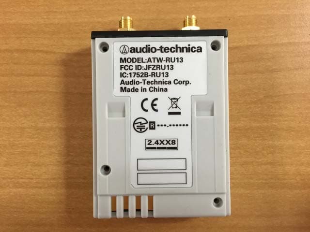
Click to zoom
Application Details
- Equipment Class
- DTS - Digital Transmission System
- Date of Grant
- Dec 04, 2014
- Application Purpose
- Original Equipment
- Date of Application
- Dec 04, 2014
- Equipment Note
- Wireless Receiver Unit
- Frequency Range
- 2403.00000000 - 2481.00000000
- Company
- Audio-Technica Corporation
- Country
- Japan
Documents & Files
Document Text
Text extracted from the exhibit documents filed with the FCC. Open a document above to read the original.
Users Manual
System 10 PRO Digital Wireless System Installation and Operation ATW-1301 UniPak ® Transmitter System ATW-1301/L Lavalier Microphone System ATW-1302 Handheld Microphone System ATW-1311 Dual UniPak ® Transmitter System ATW-1311/L Dual Lavalier Microphone System ATW-1312 UniPak ® /Handheld Combo System ATW-1312/L Lavalier/Handheld Combo System ATW-1322 Dual Handheld Microphone System **NOT A FINAL** Work In Progress System 10 PRO Installation and Operation 2 attaching it at the belt, rather than in a shirt pocket where it may be immediately adjacent to the medical device. Note also that any medical-device disruption will cease when the RF transmitting source is turned off. Please contact your physician or medical-device provider if you have any questions, or experience any problems with the use of this or any other RF equipment. Important Safety Instructions 1. Read these instructions. 2. Keep these instructions. 3. Heed all warnings. 4. Follow all instructions. 5. Do not use this apparatus near water. 6. Clean only with a dry cloth. 7. Install in accordance with the manufacturer’s instructions. 8. Do not install near any heat sources such as radiators, heat registers, stoves, or other apparatus (including amplifiers) that produce heat. 9. Unplug this apparatus during lightning storms or when unused for long periods of time. 10. Refer all servicing to qualified service personnel. Servicing is required when the apparatus has been damaged in any way, such as power-supply cord or plug is damaged, liquid has been spilled or objects have fallen into the apparatus, the apparatus has been exposed to rain or moisture, does not operate normally, or has been dropped. Thank you for choosing an Audio-Technica System 10 PRO Rack-Mount digital wireless system. You have joined thousands of other satisfied customers who have chosen our products because of their quality, performance and reliability. This wireless microphone system is the successful result of years of design and manufacturing experience. Audio-Technica’s System 10 PRO Rack-Mount is a digital wireless system designed to provide rock-solid performance along with easy setup and clear, natural sound quality. Featuring a dual-receiver chassis and remote-mount receiver unit capability, System 10 PRO Rack-Mount is available in various handheld and body-pack configurations. Operating in the 2.4 GHz range, far from TV and DTV interference, System 10 PRO Rack-Mount offers extremely easy operation and instantaneous channel selection. Up to ten channels may be used together without any frequency coordination problems or group selection issues. System 10 wireless ensures clear communications by providing three levels of diversity assurance: frequency, time, and space. Frequency Diversity sends the signal on two dynamically allocated frequencies for interference-free communication. Time Diversity sends the signal in multiple time slots to maximize immunity to multi-path interference. Finally, Space Diversity uses two antennas on each transmitter and receiver to maximize signal integrity. Each configuration of the System 10 PRO digital wireless system includes a rack-mountable receiver chassis with two receiver unit docks. Depending on the configuration, the system will also include one or two receiver units that may be docked in the chassis or mounted remotely, and one or two transmitters of either the handheld microphone or body-pack style (or one of each). Some configurations also include one or two lavalier mics that attach to the body-pack transmitters. Up to five chassis (10 receiver units) can be linked with the included RJ12 cable to allow for simultaneous use of all receivers and increased stability of the multi-channel system. Because System 10 packaging is designed to hold all versions of the system, some compartments in the carton may be intentionally left empty. The ATW-R1300 includes a switching power supply that automatically adapts to changes in mains voltage. The versatile ATW-T1001 UniPak ® body-pack transmitter has both a high- impedance input for instruments, and a low-impedance input with bias connection for use with dynamic and electret condenser microphones. The ATW-T1002 handheld transmitter features a unidirectional dynamic microphone element. Both the body-pack and handheld transmitters use internal AA batteries and have Power/Mute switches and input Trim (level) adjustments. CAUTION RISK OF ELECTRIC SHOCK DO NOT OPEN WARNING: TO REDUCE THE RISK OF FIRE OR ELECTRIC SHOCK, DO NOT REMOVE SCREWS. NO USER-SERVICEABLE PARTS INSIDE.REFER SERVICING TO QUALIFIED SERVICE PERSONNEL. WARNING: TO REDUCE THE RISK OF FIRE OR ELECTRIC SHOCK, DO NOT EXPOSE THE APPLIANCE TO RAIN OR MOISTURE. CERTIFICATION: THIS DEVICE COMPLIES WITH PART 15 OF THE FCC RULES. THIS DEVICE COMPLIES WITH INDUSTRY CANADA LICENSE-EXEMPT RSS STANDARD(S). OPERATION IS SUBJECT TO THE FOLLOWING TWO CONDITIONS: (1) THIS DEVICE MAY NOT CAUSE HARMFUL INTERFERENCE, AND (2) THIS DEVICE MUST ACCEPT ANY INTERFERENCE RECEIVED, INCLUDING INTERFERENCE THAT MAY CAUSE UNDESIRED OPERATION. Cet appareil est conforme à la/aux norme(s) CNR exempte(s) de licence d’Industrie Canada. Son fonctionnement est soumis aux deux conditions suivantes : (1) cet appareil ne doit pas causer d’interférence et (2) cet appareil doit accepter toutes les interférences, y compris celles susceptibles de provoquer un fonctionnement non souhaité. Under Industry Canada regulations, this radio transmitter may only operate using an antenna of a type and maximum (or lesser) gain approved for the transmitter by Industry Canada. To reduce potential radio interference to other users, the antenna type and its gain should be so chosen that the equivalent isotropically radiated power (e.i.r.p.) is not more than that necessary for successful communication. Conformément à la réglementation d'Industrie Canada, le présent émetteur radio peut fonctionner avec une antenne d'un type et d'un gain maximal (ou inférieur) approuvé p…
Text truncated - open the document above for the full version.
External Photos
Photo audio-technica [Model: ATW-RU13] The enclosure color is gray only for mass-production. Photo audio-technica [Model: ATW-RU13] Photo audio-technica [Model: ATW-RU13] Photo audio-technica [Model: ATW-RU13]
ID Label/Location Info
MODEL:ATW-RU13 FCC ID:JFZRU13 IC:1752B-RU13 Audio-Technica Corp. Made in China ***-****** 2.4XX8
Internal Photos
Internal Photo Audio-technica [Model: ATW-RU13] Internal Photo Audio-technica [Model: ATW-RU13]
RF Exposure Info
UL Japan, Inc. Ise EMC Lab. 4383-326 Asama-cho, Ise-shi, Mie-ken 516-0021 JAPAN Telephone : +81 596 24 8999 Facsimile : +81 596 24 8124 Applicant: Audio-Te chnica Corp. Type of Equipme nt: Wire le s s Re ce ive r Unit Model No. : ATW-RU13 FCC ID: JFZRU13 Audio-Technica Corp. declares that Model : ATW-RU13 complies with FCC radiation exposure requirement specified in the FCC Rule 2.1091 (for mobile). RF Exposure Calculations : The fo llo wing info rma tio n p ro vid e s the minimum se p a ra tio n d ista nc e fo r the highe st ga in antenna provided with the “ATW-RU13“ as calculated from (B) Limits for General Population / Uncontrolled Exposure of TABLE 1- LIMITS FOR MAXIMUM PERMISSIBLE EXPOSURE (MPE) of §1.1310 Radiofrequency ra d ia tio n e xp o s ure limits. This calculation is based on the highest EIRP possible from the system, c o nsid e ring ma ximum p o we r a nd a nte nna ga in, a nd c o nsid e ring a 1 . 0 mW/c m^ 2 unc o ntro lle d e xp o sure limit. The F riis fo rmula us e d wa s: S = (P * G) / (4* π * r 2 ) Whe re P =10.00 mW (Output powe r in The ory of Ope ration) G =1.29 Numerical Antenna gain; equal to1.10 dBi r =20.0 cm For: ATW-RU13 (Tested data)S =0.00256 mW/cm 2 [Reference] S = (P * G) / (4* π * r2) Whe re P =100.00 mW (Output power in Theory of Operation assuming 10 sets of the EUTs are co-located and used.) G =1.29 Numerical Antenna gain; equal to1.10 dBi r =20.0 cm For: ATW-RU13 (Reference data)S =0.02563 mW/cm2 No. : 10529469H RF Exposure / MP E Calculation
Test Report
Test report No. : 10529469H-B-R1 Page : 2 of 40 Issued date : November 12, 2014 Revised date : November 21, 2014 FCC ID : JFZRU13 UL Japan, Inc. Ise EMC Lab. 4383-326 Asama-cho, Ise-shi, Mie-ken 516-0021 JAPAN Telephone : +81 596 24 8999 Facsimile : +81 596 24 8124 REVISION HISTORY Original Test Report No.: 10529469H-B Revision Test report No. Date Page revisedContents - (Original) 10529469H-B November 12, 2014 - - 1 10529469H-B-R1 November 21, 2014 P4 Addition of comment to clause 2.2 1 10529469H-B-R1 November 21, 2014 P5, 6 Correction of Test Procedure and Specification for IC 1 10529469H-B-R1 November 21, 2014 P24 Addition of comment: “Not Out of band emission(Leakage Power)” Test report No. : 10529469H-B-R1 Page : 3 of 40 Issued date : November 12, 2014 Revised date : November 21, 2014 FCC ID : JFZRU13 UL Japan, Inc. Ise EMC Lab. 4383-326 Asama-cho, Ise-shi, Mie-ken 516-0021 JAPAN Telephone : +81 596 24 8999 Facsimile : +81 596 24 8124 CONTENTS PAGE SECTION 1: Customer information ......................................................................................................... 4 SECTION 2: Equipment under test (E.U.T.) ........................................................................................... 4 SECTION 3: Test specification, procedures & results ............................................................................ 5 SECTION 4: Operation of E.U.T. during testing .................................................................................... 8 SECTION 5: Conducted Emission .......................................................................................................... 11 SECTION 6: Radiated Spurious Emission ............................................................................................ 12 SECTION 7: Antenna Terminal Conducted Tests ................................................................................ 13 APPENDIX 1: Data of EMI test .............................................................................................................. 14 Conducted Emission ......................................................................................................................... 14 6dB Bandwidth ................................................................................................................................. 18 Maximum Peak Output Power .......................................................................................................... 20 Average Output Power ...................................................................................................................... 21 Radiated Spurious Emission ............................................................................................................. 22 Conducted Spurious Emission .......................................................................................................... 26 Power Density ................................................................................................................................... 29 99%Occupied Bandwidth ................................................................................................................. 31 APPENDIX 2: Test instruments ............................................................................................................. 32 APPENDIX 3: Photographs of test setup ............................................................................................... 34 Conducted Emission ......................................................................................................................... 34 Radiated Spurious Emission ............................................................................................................. 36 Worst Case Position .......................................................................................................................... 39 Test report No. : 10529469H-B-R1 Page : 4 of 40 Issued date : November 12, 2014 Revised date : November 21, 2014 FCC ID : JFZRU13 UL Japan, Inc. Ise EMC Lab. 4383-326 Asama-cho, Ise-shi, Mie-ken 516-0021 JAPAN Telephone : +81 596 24 8999 Facsimile : +81 596 24 8124 SECTION 1: Customer information Company Name : Audio-Technica Fukui Inc.* Address : 87-1, Totani, Echizen-shi, Fukui, 915-0003 Japan Telephone Number : +81-778-25-6715 Facsimile Number : +81-778-25-6705 Contact Person : Hiroki Takeichi *Remarks: Audio-Technica Fukui Inc. is on behalf of the applicant: Audio-Technica Corp. SECTION 2: Equipment under test (E.U.T.) 2.1 Identification of E.U.T. Type of Equipment : Wireless Receiver Unit Model No. : ATW-RU13 Serial No. : Refer to Clause 4.2 Rating : DC 12V Receipt Date of Sample : October 14, 2014 Country of Mass-production : China Condition of EUT : Engineering prototype (Not for Sale: This sample is equivalent to mass-produced items.) Modification of EUT : No Modification by the test lab 2.2 Product Description Model No: ATW-RU13, referred to as the EUT in this report, is the Wireless Receiver Unit. General Specification Clock frequency(ies) in the system : 24MHz Radio Specification Radio Type : Transceiver Frequency of Operation : 2403-2481MHz Modulation : GFSK Power Supply (inner) : DC 3.3V Antenna type : 1/2λ Sleeve Antenna Antenna Gain : 1.1dBi *This EUT transmits simultaneously, but the evaluation for co-location was not conducted since transmitting channels (frequencies) were different. Test report No. : 10529469H-B-R1 Page : 5 of 40 Issued date : November 12, 2014 Revised date : November 21, 2014 FCC ID : JFZRU13 UL Japan, Inc. Ise EMC Lab. 4383-326 Asama-cho, Ise-shi, Mie-ken 516-0021 JAPAN Telephone : +81 596 24 8999 Facsimile : +81 596 24 8124 SECTION 3: Test specification, procedures & results 3.1 Test Specification Test Specification : FCC Part 15 Subpart C: 2014, final revised on August 15, 2014 and effective October 14, 2014 Title : FCC 47CFR Part15 Radio Frequency Device Subpart C Intentional Radiators Section 15.207 Conducted limits Section 15…
Text truncated - open the document above for the full version.
Test Setup Photos
Test report No. : 10529469H-B-R1 Page : 34 of 40 Issued date : November 12, 2014 Revised date : November 21, 2014 FCC ID : JFZRU13 UL Japan, Inc. Ise EMC Lab. 4383-326 Asama-cho, Ise-shi, Mie-ken 516-0021 JAPAN Telephone : +81 596 24 8999 Facsimile : +81 596 24 8124 APPENDIX 3: Photographs of test setup Conducted Emission Slot in Photo 1 Photo 2 Test report No. : 10529469H-B-R1 Page : 35 of 40 Issued date : November 12, 2014 Revised date : November 21, 2014 FCC ID : JFZRU13 UL Japan, Inc. Ise EMC Lab. 4383-326 Asama-cho, Ise-shi, Mie-ken 516-0021 JAPAN Telephone : +81 596 24 8999 Facsimile : +81 596 24 8124 Conducted Emission External connect Photo 1 Photo 2 Test report No. : 10529469H-B-R1 Page : 36 of 40 Issued date : November 12, 2014 Revised date : November 21, 2014 FCC ID : JFZRU13 UL Japan, Inc. Ise EMC Lab. 4383-326 Asama-cho, Ise-shi, Mie-ken 516-0021 JAPAN Telephone : +81 596 24 8999 Facsimile : +81 596 24 8124 Radiated Spurious Emission Slot in (Below 1GHz) Photo 1 Photo 2 Test report No. : 10529469H-B-R1 Page : 37 of 40 Issued date : November 12, 2014 Revised date : November 21, 2014 FCC ID : JFZRU13 UL Japan, Inc. Ise EMC Lab. 4383-326 Asama-cho, Ise-shi, Mie-ken 516-0021 JAPAN Telephone : +81 596 24 8999 Facsimile : +81 596 24 8124 Radiated Spurious Emission External connect (Below 1GHz) Photo 1 Photo 2 Test report No. : 10529469H-B-R1 Page : 38 of 40 Issued date : November 12, 2014 Revised date : November 21, 2014 FCC ID : JFZRU13 UL Japan, Inc. Ise EMC Lab. 4383-326 Asama-cho, Ise-shi, Mie-ken 516-0021 JAPAN Telephone : +81 596 24 8999 Facsimile : +81 596 24 8124 Radiated Spurious Emission (Above 1GHz) Photo 1 Photo 2 Test report No. : 10529469H-B-R1 Page : 39 of 40 Issued date : November 12, 2014 Revised date : November 21, 2014 FCC ID : JFZRU13 UL Japan, Inc. Ise EMC Lab. 4383-326 Asama-cho, Ise-shi, Mie-ken 516-0021 JAPAN Telephone : +81 596 24 8999 Facsimile : +81 596 24 8124 Worst Case Position 30-300MHz (External: Horizontal: X-1-axis / Vertical: X-1-axis) 300-1000MHz (Slot in: Horizontal: X-axis / Vertical: X-axis) Above 1GHz (External: Horizontal: Z-2-axis / Vertical: X-2-axis) X-1-axis Y-1-axis X-2-axis Y-2-axis X-3-axis Y-3-axis Test report No. : 10529469H-B-R1 Page : 40 of 40 Issued date : November 12, 2014 Revised date : November 21, 2014 FCC ID : JFZRU13 UL Japan, Inc. Ise EMC Lab. 4383-326 Asama-cho, Ise-shi, Mie-ken 516-0021 JAPAN Telephone : +81 596 24 8999 Facsimile : +81 596 24 8124 Worst Case Position Z-1-axis X-axis Z-2-axis Y-axis Z-3-axis Z-axis End of Report
Contact Information
Applicant
Fumio Kamimura(General Manager, Engineering Planning Division)
Technical Contact
UL Japan, Inc.Takayuki Shimada
[email protected]81-596-24-8999
4383-326 Asama-cho, Ise-shi · Mie-ken · Japan
Test Firm
UL Japan, Inc. Head office EMC Lab.Tetsuya Hashimoto
Technical Specifications
| # | Rule Parts | Frequency Range | Power Output |
|---|---|---|---|
| 1 | 15C | 2.40 GHz - 2.48 GHz | 6.20 mW |
Other Applications from Audio-Technica Corporation
JFZDT3207DF2
Apr 06, 2026DESK STAND TRANSMITTER
Equipment Class
DWM - Part 15 Wireless MicrophoneJFZT210CS
Jul 17, 2024UniPak Transmitter
Equipment Class
TLD - Licensed LPAS DeviceJFZT220CS
Jul 17, 2024Handheld Transmitter
Equipment Class
TLD - Licensed LPAS DeviceJFZCKS50TW2R
Jun 10, 2024Wireless Headphones
Equipment Class
DTS - Digital Transmission SystemJFZCKS30TWPR
Apr 02, 2024Wireless Headphones
Equipment Class
DSS - Part 15 Spread Spectrum Transmitter