JFZSP65XBTWIRELESS SPEAKER
Audio-Technica Corporation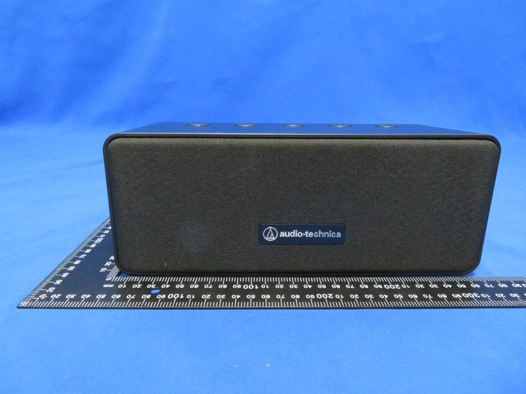
Click to zoom
Application Details
- Equipment Class
- DSS - Part 15 Spread Spectrum Transmitter
- Date of Grant
- Aug 03, 2020
- Application Purpose
- Original Equipment
- Date of Application
- Aug 03, 2020
- Equipment Note
- WIRELESS SPEAKER
- Frequency Range
- 2402.00000000 - 2480.00000000
- Company
- Audio-Technica Corporation
- Country
- Japan
Documents & Files
Document Text
Text extracted from the exhibit documents filed with the FCC. Open a document above to read the original.
Users Manual
AT-SP65XBT User manual Applicable instructions: AT-SP65XBT WIRELESS SPEAKER is suitable for mobile phones with Bluetooth function、IPAD、computer(need Bluetooth A2DP function)Or an external Bluetooth receiver,And compatible with Windows xp/Vista/Win7/Win8/Win10 Operating system platform Button function introduction 1. POWER button:Long push is power switch(Bluetooth light flashing, to be connected); 2. Pause/Play button:Short push is play pause/answer call; 3. Bluetooth button:Long push is Bluetooth to paired and connected back; 4. Volume button+:Short push is increased the volume/Long push is next track; 5.Volume button-:Short push is decreased the volume/Long push is last track; Bluetooth pairing:(Pairing peripherals need to have A2DP function in order to transmit stereo music) Two Bluetooth function devices(e.g:WIRELESS SPEAKERs and Bluetooth phones,WIRELESS SPEAKERs and PC,WIRELESS SPEAKERs and IPAD) establish encrypted wireless connection 1. Power off the speaker. 2. Long push the switch button, hear the sound , that is, power on. 3. Adjust Bluetooth device to search for Bluetooth device status,at this time, the device prompts that the blue light will flash,usually the setting step is to enter "settings”→“connecting”→“blue tooth”. Choose to add a new Bluetooth device in the device list. 4. Find the AT-SP65XBT speaker, select pairing, and then press OK. 5. After the pairing is successful, the Bluetooth function device prompts (WIRELESS SPEAKER device has been added),And ask whether to connect, select "Yes". If the connection is successful, "the blue LED will be always on. Only after the WIRELESS SPEAKER is successfully connected, the WIRELESS SPEAKER can be used. 6.Power off: long push the power on button, hear the sound, it means power off is successful. Remarks If the WIRELESS SPEAKER is low battery,when in a weak power state, sometimes it can't connect with mobile phones, PC, IPAD and other devices. Or these devices can't search for WIRELESS SPEAKERs, they must be charged immediately before they can be used. If the computer does not have a Bluetooth receiver, you need to purchase another Bluetooth receiver to pair with the AT-SP65XBT speaker. When the mobile phone is connected with Bluetooth,If the phone exceeds the connection distance(more than 10M)A disconnected Bluetooth beep will be emitted,when the phone is close to the product, it will automatically connect back Speaker charging This speaker has a built-in rechargeable battery, you must fully charge the battery before using the speaker for the first time 1. Before charging, the speaker must be power off. Do not charge it on the machine to avoid abnormal operation of the speaker. 2. Plug the speaker charging slot into a DC 5V power supply. It can be charged by USB port such as power bank or PC. 3. The red light is always on, indicating that it is charging. Power off the light when the battery is full, pull out the charger from the speaker Store speakers 1. Turn off the power of the speaker during storage and make sure that it is properly protected. 2. Avoid high temperatures (above 40°), such as high-temperature cars or direct sunlight (high temperatures can damage the surface and reduce battery life) 3. Do not expose the speaker and other parts to rain or liquid Light meaning Red light:Charging indicator, always on when charging Blue light: Bluetooth indicator, pairing status: fast flashing; paired successful but not play music: always lighting, play music: slow flashing. This equipment has been tested and found to comply with the limits for Part 15 of the FCC rules and Industry Canada license-exempt RSS standard(s). These limits are designed to provide reasonable protection against harmful interference in a residential installation. This equipment generates uses and can radiate radio frequency energy and, if not installed and used in accordance with the instructions, may cause harmful interference to radio communications. However, there is no guarantee that interference will not occur in a particular installation. If this equipment does cause harmful interference to radio or television reception, which can be determined by turning the equipment off and on, the user is encouraged to try to correct the interference by one or more of the following measures: • Reorient or relocate the receiving antenna. • Increase the separation between the equipment and receiver. • Connect the equipment to an outlet on a circuit different from that to which the receiver is connected. • Consult the dealer or an experienced radio/TV technician for help. This device complies with part 15 of the FCC rules and Industry Canada license- exempt RSS standard(s). Operation is subject to the following two conditions: (1) This device may not cause harmful interference, and (2) this device must accept any interference received, including interference that may cause undesired operation. Notice: Any changes or modifications not expressly approved by the party responsible for compliance could void the user’s authority to operate this equipment. The exposure standard for wireless transmitter employs a unit of measurement known as the Specific Absorption Rate, or SAR. The SAR limit set by the FCC and ISED is 1.6W/kg. The highest SAR value for the EUT as reported to the FCC and ISED when used next to body, as described in this user guide, is 0.01 W/kg. Cet équipement a été testé et déclaré conforme aux limites de la partie 15 des règles de la FCC et aux normes RSS exemptes de licence d'Industrie Canada. Ces limites sont conçues pour fournir une protection raisonnable contre les interférences nuisibles dans une installation résidentielle. Cet équipement génère des utilisations et peut émettre de l'énergie radiofréquence et, s'il n'est pas installé et utilisé conformément aux instructions, peut provoquer des interférences nuisibles aux communications radio. Cependant, il n'y a aucune garantie qu'aucune interférence ne se produira dans une installation particulière. …
Text truncated - open the document above for the full version.
External Photos
Report No.: 2006RSU059-UE 1 of 4 EUT External Photograph (1) EUT Photo (2) EUT Photo Report No.: 2006RSU059-UE 2 of 4 (3) EUT Photo (4) EUT Photo Report No.: 2006RSU059-UE 3 of 4 (5) EUT Photo (6) EUT Photo Report No.: 2006RSU059-UE 4 of 4 (7) EUT Photo (8) EUT Photo
Internal Photos
Report No.: 2006RSU059-UE 1 of 4 EUT Internal Photograph (1) EUT Photo (2) EUT Photo Report No.: 2006RSU059-UE 2 of 4 (3) EUT Photo (4) EUT Photo Report No.: 2006RSU059-UE 3 of 4 (5) EUT Photo (6) EUT Photo Report No.: 2006RSU059-UE 4 of 4 (7) EUT Photo (8) EUT Photo
RF Exposure Info
MRT Technology (Suzhou) Co., Ltd Report No.: 2006RSU059-U2 Phone: +86-512-66308358 Report Version: V01 Web: www.mrt-cert.com Issue Date: 08-04-2020 Page Number: 1 of 49 FCC ID: JFZSP65XBT Applicant: Audio-Technica Corporation Application Type: Certification Product: WIRELESS SPEAKER Model No.: AT-SP65XBT FCC Classification: Spread Spectrum Transmitter (DSS) FCC Rule Part(s): FCC 47 CFR Part 2.1093 Test Procedure(s): IEEE 1528:2013; IEEE C95.1- 2005; KDB 447498 D01v06; KDB 865664 D01v01r04 Test Date: August 03, 2020 SAR MEASUREMENT REPORT Reviewed By: ( Jame Yuan ) Approved By: ( Robin Wu ) The test results relate only to the samples tested. This equipment has been shown to be capable of compliance with the applicable technical standards as indicated in the measurement report and was tested in accordance with the measurement procedures specified in IEEE1528, KDB 447498 and KDB 865664. Test results reported herein relate only to the item(s) tested. The test report shall not be reproduced except in full without the written approval of MRT Technology (Suzhou) Co., Ltd. Report No.: 2006RSU059-U2 Page Number: 2 of 49 Revision History Report No. Version Description Issue Date Note 2006RSU059-U2 Rev. 01 Initial Report 08-04-2020 Valid Report No.: 2006RSU059-U2 Page Number: 3 of 49 CONTENTS Description Page 1. Introduction ............................................................................................................................ 6 1.1. Scope ........................................................................................................................... 6 1.2. MRT Test Location ....................................................................................................... 6 2. Product Information ............................................................................................................... 7 2.1. General Description for EUT ......................................................................................... 7 2.2. Product Specification Subjective to this Report ............................................................. 7 2.3. Description of Available Antennas ................................................................................ 7 2.4. Ancillary Equipment ...................................................................................................... 7 3. Summary of Test Result ........................................................................................................ 8 3.1. Test Standards ............................................................................................................. 8 3.2. Environment Condition ................................................................................................. 8 3.3. RF Exposure Limits ...................................................................................................... 8 3.4. Test Result Summary ................................................................................................... 9 4. Specific Absorption Rate (SAR).......................................................................................... 10 4.1. Introduction ................................................................................................................. 10 4.2. Definition .................................................................................................................... 10 5. DASY6 Measurement System ............................................................................................. 11 5.1. Introduction ................................................................................................................. 11 5.2. DASY6 Measurement System Diagram ...................................................................... 11 5.3. System Components Details ....................................................................................... 12 6. The SAR Measurement Procedure ..................................................................................... 23 6.1. Measurement Process Diagram.................................................................................. 23 6.2. Test Position Definition ............................................................................................... 24 6.3. Test Procedure ........................................................................................................... 27 7. System Verificaiton.............................................................................................................. 29 7.1. Tissue Check .............................................................................................................. 29 7.2. System Check ............................................................................................................ 32 8. Analysis and Results ........................................................................................................... 34 8.1. Antenna Location ........................................................................................................ 34 8.2. Conducted Power ....................................................................................................... 35 8.3. SAR Exclusion Analysis .............................................................................................. 36 Report No.: 2006RSU059-U2 Page Number: 4 of 49 8.4. Required Configurations of SAR Test ......................................................................... 38 8.5. SAR Test Results ....................................................................................................... 39 8.6. Estimated SAR Calculation ......................................................................................... 40 9. Simultaneous Transmission Analysis ................................................................................ 41 10. Test Equipment Used .......................................................................................................... 42 11. Measu…
Text truncated - open the document above for the full version.
RF Exposure Info
Return Loss and Impedance Indicated By Head Tissue Meas. Items Original Value Current Value Deviation Return Loss(dB) -28.040 -26.45 -5.67% 1.379Ω Real part -2.216Ω Imaginary part Impedance 53.281Ω + 2.445jΩ 54.66Ω + 0.229Ω Test Date: 2020/05/10
Test Report
MRT Technology (Suzhou) Co., Ltd Report No.: 2006RSU059-U1 Phone: +86-512-66308358 Report Version: V01 Web: www.mrt-cert.com Issue Date: 08-01-2020 Page Number: 1 of 104 FCC ID: JFZSP65XBT ISED: 1752B-SP65XBT APPLICANT: Audio-Technica Corporation Application Type: Certification Product: WIRELESS SPEAKER Model No.: AT-SP65XBT Brand Name: audio-technica FCC Classification: FCC Part 15 Spread Spectrum Transmitter (DSS) FCC Rule Part(s): Part 15 Subpart C (Section 15.247) ISED Rule(s): RSS-247 Issue 2, RSS-GEN Issue 5 Test Procedure(s): ANSI C63.10-2013 Test Date: June 22 ~ 28, 2020 MEASUREMENT REPORT FCC PART 15.247 / RSS-247 Bluetooth Reviewed By: ( Jame Yuan ) Approved By: ( Robin Wu ) The test results relate only to the samples tested. This equipment has been shown to be capable of compliance with the applicable technical standards as indicated in the measurement report and was tested in accordance with the measurement procedures specified in ANSI C63.10-2013. Test results reported herein relate only to the item(s) tested. The test report shall not be reproduced except in full without the written approval of MRT Technology (Suzhou) Co., Ltd. Report No.: 2006RSU059-U1 Page Number: 2 of 104 Revision History Report No. Version Description Issue Date Note 2006RSU059-U1 Rev. 01 Initial Report 08-01-2020 Valid Report No.: 2006RSU059-U1 Page Number: 3 of 104 CONTENTS Description Page General Information ....................................................................................................................... 6 1. INTRODUCTION ..................................................................................................................... 7 1.1. Scope ........................................................................................................................... 7 1.2. MRT Test Location ....................................................................................................... 7 2. PRODUCT INFORMATION ..................................................................................................... 8 2.1. Equipment Description .................................................................................................. 8 2.2. Product Specification Subjective to this Standard ......................................................... 8 2.3. Working Frequencies for this Report ............................................................................. 9 2.4. Pseudorandom Frequency Hopping Sequence ........................................................... 10 2.5. Test Mode .................................................................................................................. 10 2.6. Test Software ............................................................................................................. 10 2.7. Duty Cycle ................................................................................................................... 11 2.8. EMI Suppression Device(s)/Modifications .................................................................... 11 2.9. Labeling Requirements ............................................................................................... 12 2.10. Test Environment Condition ........................................................................................ 12 3. DESCRIPTION of TEST ........................................................................................................ 13 3.1. Evaluation Procedure ................................................................................................. 13 3.2. AC Line Conducted Emissions ................................................................................... 13 3.3. Radiated Emissions .................................................................................................... 14 4. ANTENNA REQUIREMENTS ................................................................................................ 15 5. TEST EQUIPMENT CALIBRATION DATE ............................................................................ 16 6. MEASUREMENT UNCERTAINTY ......................................................................................... 18 7. TEST RESULT ...................................................................................................................... 19 7.1. Summary .................................................................................................................... 19 7.2. 20dB Bandwidth & 99% Bandwidth Measurement ...................................................... 20 7.2.1. Test Limit ................................................................................................................ 20 7.2.2. Test Procedure used ............................................................................................... 20 7.2.3. Test Setting ............................................................................................................. 20 7.2.4. Test Setup ............................................................................................................... 21 7.2.5. Test Result .............................................................................................................. 22 7.3. Output Power Measurement ....................................................................................... 26 7.3.1. Test Limit ................................................................................................................ 26 7.3.2. Test Procedure Used .............................................................................................. 26 Report No.: 2006RSU059-U1 Page Number: 4 of 104 7.3.3. Test Setting ............................................................................................................. 26 7.3.4. Test Setup ............................................................................................................... 26 7.3.5. Test Result ............................................................................…
Text truncated - open the document above for the full version.
Test Report
Report No.: 2006RSU059-U1 Page Number: 48 of 104 Operation Frequency Range of 20dB Bandwidth within Hopping Mode Channel 00 (2402MHz) Channel 78 (2480MHz) Channel 00 (2402MHz) Channel 78 (2480MHz) Channel 00 (2402MHz) Channel 78 (2480MHz) Report No.: 2006RSU059-U1 Page Number: 49 of 104 7.8. Conducted Spurious Emissions Measurement 7.8.1.Test Limit In any 100 kHz bandwidth outside the frequency band in which the spread spectrum or digitally modulated intentional radiator is operating, the radio frequency power that is produced by the intentional radiator shall be at least 20 dB below that in the 100 kHz bandwidth within the band that contains the highest level of the desired power, based on either an RF conducted or a radiated measurement, provided the transmitter demonstrates compliance with the peak conducted or a radiated measurement, provided the transmitter demonstrates compliance with the peak conducted power limits. If the transmitter complies with the conducted power limits based on the use of RMS averaging over a time interval, the attenuation required under this paragraph shall be 30 dB instead of 20 dB. 7.8.2.Test Procedure Used ANSI C63.10-2013 - Section 7.8.8 7.8.3.Test Setting 1. Span = Wide enough to capture the peak level of the in-band emission and all spurious emissions (e.g., harmonics) from the lowest frequency generated in the EUT up through the 10th harmonic. Typically, several plots are required to cover this entire span. 2. RBW = 100kHz 3. VBW = 300kHz 4. Detector = Peak 5. Sweep time = Auto couple 6. Trace mode = Max hold 7. Trace was allowed to stabilize 8. Set the marker on the peak of any spurious emission recorded. The level displayed must comply with the limit specified in this section. Report No.: 2006RSU059-U1 Page Number: 50 of 104 7.8.4.Test Setup Report No.: 2006RSU059-U1 Page Number: 51 of 104 7.8.5.Test Result Product WIRELESS SPEAKER Test Engineer Lewis Huang Test Site TR3 Test Date 2020/06/24 Test Mode Channel No. Frequency (MHz) Limit Result DH5 00 2402 20dBc Pass DH5 39 2441 20dBc Pass DH5 78 2480 20dBc Pass 2DH5 00 2402 20dBc Pass 2DH5 39 2441 20dBc Pass 2DH5 78 2480 20dBc Pass 3DH5 00 2402 20dBc Pass 3DH5 39 2441 20dBc Pass 3DH5 78 2480 20dBc Pass Report No.: 2006RSU059-U1 Page Number: 52 of 104 DH5 Conducted Spurious Emissions Channel 00 (2402MHz) Channel 39 (2441MHz) Channel 78 (2480MHz) Report No.: 2006RSU059-U1 Page Number: 53 of 104 2DH5 Conducted Spurious Emissions Channel 00 (2402MHz) Channel 39 (2441MHz) Channel 78 (2480MHz) Report No.: 2006RSU059-U1 Page Number: 54 of 104 3DH5 Conducted Spurious Emissions Channel 00 (2402MHz) Channel 39 (2441MHz) Channel 78 (2480MHz) Report No.: 2006RSU059-U1 Page Number: 55 of 104 7.9. Radiated Spurious Emission Measurement 7.9.1.Test Limit All out of band emissions appearing in a restricted band as specified in Section 15.205 of the Title 47 CFR must not exceed the limits shown in Table per Section 15.209. FCC 15.209 Limit Frequency [MHz] Field Strength [uV/m] Measured Distance [Meters] 0.009 - 0.490 2400/F (kHz) 300 0.490 - 1.705 24000/F (kHz) 30 1.705 - 30 30 30 30 - 88 100 3 88 - 216 150 3 216 - 960 200 3 Above 960 500 3 All out of band emissions appearing in a restricted band as specified in Section 8.10 of the RSS-Gen must not exceed the limits shown in Table per Section 8.9. RSS-Gen Section 8.9 Limit Frequency (MHz) Field Strength (μV/m) Magnetic Field Strength (H-Field) (μA/m) Measured Distance (m) 0.009 - 0.490 -- 6.37/F (F in kHz) 300 0.490 - 1.705 -- 6.37/F (F in kHz) 30 1.705 - 30 -- 0.08 30 30 - 88 100 -- 3 88 - 216 150 -- 3 216 - 960 200 -- 3 Above 960 500 -- 3 Report No.: 2006RSU059-U1 Page Number: 56 of 104 7.9.2.Test Procedure Used ANSI C63.10-2013 - Section 6.3 (General Requirements) ANSI C63.10-2013 - Section 6.4 (Standard test method below 30MHz) ANSI C63.10-2013 - Section 6.5 (Standard test method above 30MHz to 1GHz) ANSI C63.10-2013 - Section 6.6 (Standard test method above 1GHz) 7.9.3.Test Setting Table 1 - RBW as a function of frequency Frequency RBW 9 ~ 150 kHz 200 ~ 300 Hz 0.15 ~ 30 MHz 9 ~ 10 kHz 30 ~ 1000 MHz 100 ~ 120 kHz Above 1000 MHz 1 MHz Quasi-Peak Measurements below 1GHz 1. Analyzer center frequency was set to the frequency of the radiated spurious emission of interest 2. Span was set greater than 1MHz 3. RBW = as specified in Table 1 4. Detector = CISPR quasi-peak 5. Sweep time = auto couple 6. Trace was allowed to stabilize Peak Measurements above 1GHz 1. Analyzer center frequency was set to the frequency of the radiated spurious emission of interest 2. RBW = 1MHz 3. VBW = 3MHz 4. Detector = peak 5. Sweep time = auto couple 6. Trace mode = max hold 7. Trace was allowed to stabilize Report No.: 2006RSU059-U1 Page Number: 57 of 104 Average Measurements above 1GHz 1. Analyzer center frequency was set to the frequency of the radiated spurious emission of interest 2. RBW = 1MHz 3. VBW; If the EUT duty cycle is < 98%, set VBW ≥ 1/T. T is the minimum transmission duration. 4. Detector = Peak 5. Sweep time = auto 6. Trace mode = max hold 7. Trace was allowed to stabilize 7.9.4.Test Setup Below 1GHz Test Setup: Report No.: 2006RSU059-U1 Page Number: 58 of 104 Above 1GHz Test Setup: Report No.: 2006RSU059-U1 Page Number: 59 of 104 7.9.5.Test Result Product WIRELESS SPEAKER Test Engineer Flay Yang Test Site AC1 Test Date 2020/06/24 Test Mode DH5 Test Channel 00 Remark 1. Average measurement was not performed if peak level lower than average limit. 2. Other frequency was 20dB below limit line within 1-18GHz, there is not show in the report. Mark Frequency (MHz) Reading Level (dBμV) Factor (dB) Measure Level (dBμV/m) Limit (dBμV/m) Margin (dB) Detector Polarization 4808.0 36.8 5.8 42.6 74.0 -31.4 Peak Horizontal 7205.0 37.9 11.5 49.4 74.0 -24.6 Peak Horizontal 8420.5 32.4 12.5 44.9 74.0 -29.1 Peak Horizontal 10273.5 31.4 17.3 48.7 74.0 -25.3 Peak Horizontal 4808.0 34.9 5.8 40.7 74.0 -33.3 Peak Vertical 5904.5 33.2 7.8 41.0 74.0 -33.0 Peak Vertical 7485.5 33.5 11.8 45.3 74.0 -28…
Text truncated - open the document above for the full version.
Test Setup Photos
Report No.: 2006RSU059-UT 1 of 4 RF Test Setup Photograph Description: Front View of Conducted Emission Test Setup for Power Port Description: Back View of Conducted Emission Test Setup for Power Port Report No.: 2006RSU059-UT 2 of 4 Description: Radiated Emission Test Setup for below 1GHz Description: Radiated Emission Test Setup for above 1GHz Report No.: 2006RSU059-UT 3 of 4 Description: Body Back Position with 0mm gap Description: Body Left Position with 0mm gap Report No.: 2006RSU059-UT 4 of 4 Description: Body Top Position with 0mm gap
Contact Information
Applicant
Fumio Kamimura(General Manager, Engineering Planning Division)
Test Firm
MRT Technology (Suzhou) Co., Ltd.Mr. Marlin Chen
[email protected]+86-512-66308358
Technical Specifications
| # | Rule Parts | Frequency Range | Power Output |
|---|---|---|---|
| 1 | 15C | 2.40 GHz - 2.48 GHz | 2.00 mW |
Other Applications from Audio-Technica Corporation
JFZDT3207DF2
Apr 06, 2026DESK STAND TRANSMITTER
Equipment Class
DWM - Part 15 Wireless MicrophoneJFZT210CS
Jul 17, 2024UniPak Transmitter
Equipment Class
TLD - Licensed LPAS DeviceJFZT220CS
Jul 17, 2024Handheld Transmitter
Equipment Class
TLD - Licensed LPAS DeviceJFZCKS50TW2R
Jun 10, 2024Wireless Headphones
Equipment Class
DTS - Digital Transmission SystemJFZCKS30TWPR
Apr 02, 2024Wireless Headphones
Equipment Class
DSS - Part 15 Spread Spectrum Transmitter