JFZT1801DBELTPACK TRANSMITTER
Audio-Technica Corporation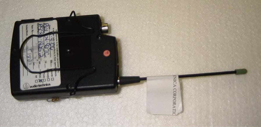
Click to zoom
Application Details
- Equipment Class
- TBT - Licensed Broadcast Transmitter Worn on Body
- Date of Grant
- Oct 16, 2006
- Application Purpose
- Original Equipment
- Date of Application
- Oct 15, 2006
- Equipment Note
- BELTPACK TRANSMITTER
- Frequency Range
- 655.50000000 - 680.37500000
- Company
- Audio-Technica Corporation
- Country
- Japan
Documents & Files
Document Text
Text extracted from the exhibit documents filed with the FCC. Open a document above to read the original.
Users Manual
1800 Series (Dual-Channel) Owners Manual 1800 Series Camera-mount UHF Wireless Microphone Systems (dual-channel) ATW-1821 Body-pack Transmitters System ATW-1822 Plug-on Transmitters System ATW-1823 Plug-on and Body-pack Transmitters System Installation and Operation This device complies with part 15 of the FCC Rules. Operation is subject to the condition that this device does not cause harmful interference. This device complies with INDUSTRY CANADA R.S.S. 210, en conformité avec IC: RSS- 210/CNR210. Operation is subject to the following conditions: 1) This device may not cause harmful interference and 2) this device must accept any interference received, including interference which may cause undesired operation. Changes or modifications not expressly approved by Audio-Technica could void your authority to operate this equipment. Notice to individuals with implanted cardiac pacemakers or AICD devices : Any source of RF (radio frequency) energy may interfere with normal functioning of the implanted device. All wireless microphones have low-power transmitters (less than 0.05 watts output) which are unlikely to cause difficulty, especially if they are at least a few inches away. However, since a “body-pack” mic transmitter typically is placed against the body, we suggest attaching it at the belt, rather than in a shirt pocket where it may be immediately adjacent to the medical device. Note also that any medical-device disruption will cease when the RF transmitting source is turned off. Please contact your physician or medical-device provider if you have any questions, or experience any problems with the use of this or any other RF equipment. CAUTION! The circuits inside the receiver and transmitter have been precisely adjusted for optimum performance and compliance with federal regulations. Do not attempt to open the receiver or transmitter. To do so will void the warranty, and may cause improper operation. Warning: To prevent fire or shock hazard, do not expose this appliance to rain or moisture. Attention: Pour prévenir feu ou choc électrique, ne pas exposé l’appareil à la pluie ou à l’humidité. 1800 Series System Components (Dual-Channel) All 1800 Series dual-channel systems include: ATW-R1820 Dual-channel receiver Two detachable antennas Two 18” output cables, TA3F to XLRM Pouch with belt clip (holds receiver) Hook & loop fastener mount Each of the three dual-channel camera-mount wireless systems also includes the following: ATW-1821 Camera-mount UHF Wireless Microphone System (dual-channel) with Body-pack Transmitters Two ATW-T1801 UniPak™ Body-pack Transmitters Two Omnidirectional Lavalier Microphones ATW-1822 Camera-mount UHF Wireless Microphone System (dual-channel) with Plug-on Transmitters Two ATW-T1802 Plug-on Transmitters ATW-1823 Camera-mount UHF Wireless Microphone System (dual-channel) with Plug-on and Body-pack Transmitters ATW-T1801 UniPak™ Body-pack Transmitter ATW-T1802 Plug-on Transmitter Omnidirectional Lavalier Microphone System Features (Dual-Channel) • Two completely independent receiver channels in a single unit, for simultaneous operation of two microphones • Extremely compact receiver is easy to mount on a camera with included Velcro-type fastener • UHF reception with 996 frequencies selectable in 25 kHz steps • Automatic frequency scanning for easy selection of open channels • Tone Lock™ squelch system eliminates interference when transmitter is off (Transmitters are compatible with Advanced Digital Tone Lock™ squelch on Audio-Technica’s 3000 Series UHF Wireless Systems) • Two independent balanced outputs (you can assign function of each, independently) • Headphone monitor output with independent level control • Battery fuel-level indicators on transmitters and receiver • Soft-touch controls for easy frequency selection • True Diversity operation for resistance to multi-path interference and dropouts • LCD frequency and battery status display with backlight • Antenna and AF Peak LED indicators • Easy, user-friendly operation • Clear, natural sound quality • Powered by AA batteries Quick Overview of System Operation Thank you for purchasing this Audio-Technica 1800 Series Dual-channel Camera-mount UHF Wireless Microphone System. All 1800 Series systems are designed primarily to be used with video cameras, with the ATW-R1820 Dual-channel Receiver mounted on a camera and connected to the camera’s audio input; they may also be used with other components equipped with microphone-level input(s). This system is equipped with a dual receiver, which consists of two completely independent receiver channels in a single unit, for simultaneous operation of two microphones. First, insert batteries. (See Receiver Battery Installation, page __.) Note: The ATW-R1820 Dual-channel Receiver also functions without batteries if connected to an external power supply (12V DC source, 500 mA nominal current, not included). Next, mount the ATW-R1820 Dual-channel Receiver to your camera using the included hook & loop fastener mount or another accessory bracket (not included); or use the included pouch with belt clip to attach the ATW-R1820 to your belt. Connect the output cable(s) to the ATW-R1820 and your video camera (and/or audio mixer). (See Output A, Output B, and Output Select Switch callouts, page ___). Turn the ATW-R1820 Power Switch on. Choose “1” to activate only Receiver Channel 1 (power/peak LED 1 should light red); this option will increase useable battery life. Choose “Both” to activate both receiver channels (power/peak LEDs 1 and 2 should light red). (See Power Switch with four positions: External, Off, 1, Both callout, page ___.) Select a frequency for Receiver Channel 1 and Receiver Channel 2. (See Selecting Frequencies on your Dual-channel Receiver, page ___.) NOTE: Receiver Channel 1 and Receiver Channel 2 must be set to different frequencies to avoid interference. Transmitter-Receiver pairs must be set to identical frequencies: Set Transmitter 1 to the same frequency as…
Text truncated - open the document above for the full version.
Cover Letter(s)
Audio-Technica U.S., Inc. 1221 Commerce Drive Phone: 330-686-2600 [email protected] Stow, OH 44224-1760 Fax: 330-688-3752 August 7, 2006 Equipment Authorization Division Office of Engineering and Technology Federal Communications Commission 7435 Oakland Mills Road Columbia, MD 21046 Ref: FCC ID: JFZT1801D Request for Confidentiality Dear Sirs: With regard to the referenced application, Audio-Technica, is requesting confidentiality of certain sections of the accompanying documents. The documents for which Audio Technica is requesting confidentiality are: 2402UT6 Circuit Diagram.pdf 2402UT6 Block diagram.pdf This request is made under the provisions of Section 0.457(d) of the Commission’s Rules, and Section 552(b)(4) of the Freedom of Information Act. The material for which confidentiality is requested falls within the scope of Section 552(b)(4) as trade secrets and includes material covered by Section 0.459 of the Commission’s Rules. Sincerely, Jacquelynn Green Vice President R&D Audio-Technica U.S., Inc.
External Photos
AUDIO TECHNICA CORP. FCC ID: JFZT1801D EXTERNAL PHOTOS
Internal Photos
AUDIO TECHNICA CORP. FCC ID: JFZT1801D INTERNAL PHOTOS
Operational Description
Operational Description of ATW-T1801D Transmitter 1. Audio 1.1 Audio signal produced by the Microphone element is feed in to the audio IC 200. 1.2 Audio signal injected in to the IC200 is then amplified by the internal AF Amp. 1.3 Amplified audio signal is feed in to the compander circuit that const by IC250 operational amp and IC251compander IC, and compressed. 1.4 Audio signal that coming from the Guitar cable also feed in to the IC200, through the buffer amplifier, then feed in to the same AF amp listed item 1.2. 1.5 The compressed audio signal Is feed in to the IC200 and pre-emphasized and out from the IC200 and adjusted it level to appropriate by VR201. 1.6 32.15KHz signal that produced by the tone generator circuit in the IC200, is superposed with the control signal that produced by the micro-controller IC300 and out from the IC200 and adjusted it level to appropriate by VR200. 1.7 Properly adjusted Audio and tone signals are mixed and send to the VCO, VCO100. 1.8 Q280 detects peak signal level that feed in to the microphone and line input and dimmer the Power LED D349. 2. RF 1.9 RF signal produced by the VCO, VCO100 is modulate by the mixed audio and tone signal. 1.10 Modulated RF signal is through the buffer amp Q101, feed to the RF amplifier, consist by Q102 and Q103. 1.11 Amplified RF signal is then set it RF output power to; Hi position, 30mW by VR101and Low position, 10mW by VR100. 1.12 Amplified RF signal is suppress it harmonics by through Low pass filter consist by L104 to 108, C132 to 136 and feed in to Antenna terminal. 1.13 RF signal feed in to the Antenna terminal is then transmitted to the air by antenna screwed on to it.
Parts List/Tune Up Info
1 2344073301 2344051301 2354040301 2344051501 2344051401 2343012108 0502731001 2344073401 2369105801 2354044003 2354039021 2344066301 2344052201 0856609201 0352109101 2364000601 0856326601 2343009901 2364017601 2343012001 0855208701 2354040401 2354042001 2364000661 2364000461 9347001301 2354066401 9510021201 2354041701 2354041502 2354042101 0863037601 2353006401 2354045902 2354043201 2354041601 2344052101 2344073502 0842048702 2344054801 9625001001 145403760
Parts List/Tune Up Info
ATW-T1801 Parts List_electric PCS. P.CODEDESCRIPTION 1236910580PCB ASY-T1801-D 1236910590PCB ASY-T1801AN-D 1236910630PCB)T1801AN 1951600020C/CN)MM7329-2700-T 1971001980BP)B2P-BC-2 1971003650BP)IMSA-9120B-15-PT1 1971002000BP)DF13-4P-1.25H(21) 1935601820C/IC)MB1511PFV-T 1935602330C/IC)DREAMT1-T 1935602390C/IC)XC61CN4002NR-T 1935602500C/IC)NJM2068MD-T 1935600031C/IC)NE572D 1939600350C/VCO)T668-T 3932601590C/SD)HSC119-T 8932601800C/SD)HZC6.2-T 2932600201C/SD)1SS302-T(TE85L) 1930601210C/TR)2SC4226-24-T 2930601410C/TR)2SC5226-4-T 1930600770C/TR)2SB1295-6 1930601560C/TR)DTA114YKA-T 1930601221C/TR)2SC4738-Y-T 1930601690C/TR)HN1C01F-Y-T 2922805670C/L)1608-FSL12NJ-T 3922805660C/L)1608-FSL10NJ-T 2922805680C/L)1608-FSL15NJ-T 1922805610C/L)1608-FSL3N9S-T 4922603640C/L)2520-100K-T 1908602221C/SR)RH02B1C-223-T 1908602260C/SR)RH02B1C-101-T 1908602210C/SR)RH02B1C-104-T 1908602250C/SR)RH02B1C-103-T 13905611330C/RK)1005-000J-T 8905611340C/RK)1005-100J-T 1905611420C/RK)1005-220J-T 1905611550C/RK)1005-101J-T 3905611590C/RK)1005-151J-T 2905611620C/RK)1005-201J-T 1905611670C/RK)1005-331J-T 1905612580C/RK)1005-681J-T 6905611770C/RK)1005-102J-T 1905611840C/RK)1005-202J-T 7905611850C/RK)1005-222J-T 1905611880C/RK)1005-302J-T 1905611910C/RK)1005-392J-T 2905611930C/RK)1005-472J-T 4905611940C/RK)1005-512J-T 1905611960C/RK)1005-622J-T 2905611990C/RK)1005-822J-T 5905612010C/RK)1005-103J-T 3905612600C/RK)1005-153J-T 3905612070C/RK)1005-203J-T 1905612100C/RK)1005-303J-T 6905612150C/RK)1005-473J-T 1905612210C/RK)1005-823J-T 3905612230C/RK)1005-104J-T 1905612390C/RK)1005-564J-T 1905608410C/RK)1608-205J-T 1905612610C/RK)1005-273J-T 1916602480C/CS)3216-1V104M-T 2916609320C/CS)2012-1C334M-T 3916606720C/CS)2012-1C105M-T 2916609280C/CS)2012-1A155M-T 9916609290C/CS)2012-1A225M-T 4916609310C/CS)2012-1A475M-T 5916604940C/CS)3216-1A106M-T 1916606710C/CS)2012-0J106M-T 2916609210C/CS)3528-1C106M-T 1916609250C/CS)2012-0G226M-T 1916609440C/CS)3528-0J476M-T 1915802200C/CC)1005CK-1H010C-T 3915802210C/CC)1005CK-1H020C-T 4915802240C/CC)1005CH-1H050C-T 1915802250C/CC)1005CH-1H060D-T 1915802350C/CC)1005CH-1H330J-T 2915802370C/CC)1005CH-1H470J-T 1915802380C/CC)1005CH-1H560J-T 7915802410C/CC)1005CH-1H101J-T 3915802490C/CC)1005CH-1H471J-T 1915801561C/CC)1608CH-1H821J-T 2915802540C/CK)1005B-1H102K-T 1915802560C/CK)1005B-1H222K-T 9915802600C/CK)1005B-1E103K-T 7915802660C/CK)1005B-1A104K-T 2912600330C/CQ)2125-1C103J-T 1917600440C/CF)3225-1H473J-T 1971003660BP)IMSA-9120S-15 1937006870XTL)LP-3.5 9.000MHz 1236910600PCB ASY-T1801DG-D 1236910640PCB)T1801DG 1936800410C/IC)HD64F38124WV 1936602480C/IC)S-93C46AMFN-TBG 1935602340C/IC)NJU6366DF1-T 1935602390C/IC)XC61CN4002NR-T 1935602350C/IC)LTC3401EMS 1935602430C/IC)XC6204B502MR-T 1932800360C/SD)1SS400GT2R-T 2932600740C/SD)DCG010-T 3932601420C/SD)RB521S-30 1932601590C/SD)HSC119-T 4932601800C/SD)HZC6.2-T 2934800080C/LED)SML-A10MT-T 1934800060C/LED)MSL-155B6-T 1930601640C/TR)CPH3106-T 1930601221C/TR)2SC4738-Y-T 1930800350C/TR)2SA1037AK-T 4948600070C/SW)SMTE3-04E-T 1918600240C/SC)TZC03R100A110-T 1922607060C/L)CDRH3D16-4R7 2922603640C/L)2520-100K-T 1922607900C/L)1608-LK1R0M-T 1922608200C/L)1608-LK330M-T 6905611330C/RK)1005-000J-T 1905611340C/RK)1005-100J-T 2905611550C/RK)1005-101J-T 1905611630C/RK)1005-221J-T 1905611720C/RK)1005-511J-T 1905611810C/RK)1005-152J-T 2905611940C/RK)1005-512J-T 4905612010C/RK)1005-103J-T 1905612080C/RK)1005-223J-T 1905612130C/RK)1005-393J-T 1905612150C/RK)1005-473J-T 1905612150C/RK)1005-473J-T 1905612590C/RK)1005-821J-T 13905612150C/RK)1005-473J-T 4905612230C/RK)1005-104J-T 4905612300C/RK)1005-224J-T 1905626220C/RK)1005-3003F-T 1905624920C/RN)1005-1004F-T 1916609310C/CS)2012-1A475M-T 1916606710C/CS)2012-0J106M-T 3916604940C/CS)3216-1A106M-T 2916609210C/CS)3528-1C106M-T 1916603032C/CS)3528-1A336M-T 4916609630C/CS)3528-0J107M-T 6915802660C/CK)1005B-1A104K-T 1915802200C/CC)1005CK-1H010C-T 1915802300C/CC)1005CH-1H120J-T 1915802330C/CC)1005CH-1H220J-T 1915802410C/CC)1005CH-1H101J-T 1915802490C/CC)1005CH-1H471J-T 1915802540C/CK)1005B-1H102K-T 6915802600C/CK)1005B-1E103K-T NOTES CNP100 CNP101 CNP103 CNP201 IC141 IC200 IC201 IC250 IC251 VCO100 D140,D207,D280 D200,D201,D202,D203,D204,D208,D 209,D210 D250,D251 Q101 Q102,103 Q104 Q106 Q140 Q280 L101,L102 L103,L104,L107 L105,L106 L108 L200,L201,L202,L203 VR100 VR101 VR200 VR201 R103,R125,R153,R157,R158,R159,R 236,R115,R119,R240 R151,R287,R288 R113,R140,R259,R262,R263,R264,R 265,R268 R100 R230 R102,R104,R161 R156,R239 R110 R211 R114,R118,R146,R162,R210,R250 R261 R101,R112,R142,R143,R144,R154,R R206 R220 R160,216 R116,R120,R148,R149 R260 R111,R219 R122,R123,R124,R217,R253 R121,R254,R255 R117,R147,R209 R252 R126,R150,R212,R214,R231,R232 R280 R145,R281,R282 R284 R283 R285 C215 C258,C270 C142,C269,C281 C212,C213 C100,C223,C227,C231,C240,C250,C 252,C257,C280 C104,C140,C211,C249 C119,C124,C127,C216,C278 C224 C266,268 C255 C103 C136 C115,C121,C135 C130,C132,C133,C134 C145 C254 C110,C214 C228 C101,C111,C114,C118,C120,C123,C C221,C229,C232 C230 C148,C220 C222 C102,C125,C126,C128,C129,C146,C 265,C267,C271 C105,C141,C144,C204,C218,C225,C C233,C251 C259 CNP200 XTAL300 IC300 IC301 IC302 IC343 IC344 IC345 D341 D342,D343 D344,D345,D346 D347 D348,D352,D353,D354 D350,D351 D349 Q341 Q342 Q343 SW300,SW301,SW302,SW340 VC300 L341 L342,L343 L344 L345 R308,R312,R353,R356,R357,R358 R354 R302,R363 R318 R343 R321 R342,R346 R320,R326,R344,R364 R347 R352 R303 R309 R322 R305,R311,R313,R327,R328,R329,R 330,R331, R332,R333,R334,R335,R349 R317,R336,R345,R348 R319,R323,R324,R325 R351 R350 C308 C340 C300,C302,C304 C354,C355 C358 C342,C357,C361,C363 C310,C311,C312,C352,C353,C366 C365 C307 C360 C356 C359 C351 C301,C303,C305,C309,C341,C350
Parts List/Tune Up Info
No. FM23-0*** Model Name ATW-T1801 ATW-T1801 Adjustment Procedure 1. Required Equipment a. Audio Signal Generator : Leader LAG-126 b. Oscilloscope : Kenwood CS-4135 c. Spectrum Analyzer : Advantest R3361A d. Modulation Analyzer : Anritsu MS616B e. Noise Meter : National VP-9680A f. DC Power Supply : Kenwood PA18-1.2A g. Multi Meter : Agilent 34401A h. RF Custom cable, BNC to MM121454 : Audio-Technica custom made RF cable 2. How to enter the Adjustment Mode 2-1 Push and hold both SW300 (SET) and SW340 (Power) together until turn the power “ON” 2-2 Push and hold both SW302 (UP) and SW301 (Down) together until “ADJ” appeared on LCD screen. 3. Adjustment 3-1 Frequency response 3-2-1 Spectrum Analyzer set up: Center Frequency 668.000MHz Frequency Span 100KHz Counter Mode ON 3-2-2 T1801 set up Frequency 668.000MHz RF HI / LOW RF HI AF Gain -6DB Lock NO.LOC MIC/INST MIC PE ON/OFF PE ON LMT. ON / OFF LMT.OFF PRESET PRESET QUIT QUIT 3-2-3 Adjustment a. Adjust the VC300 to put main carrier signal to center of the screen on spectrum analyzer. b. Adjust the VR101 to set main carrier peak leading to 120.1dBuV. c. Using power button and switch T1801 output power setting to “RF LOW” d. Adjust the VR100 to set main carrier peak leading to 115dBuV. 3-2 Pilot tone deviation level 3-3-1 Spectrum Analyzer set up Center Frequency 668.000MHz Span 100KHz Counter Mode ON DSP LINE ON, Set it to 20dBc below peak 3-3-2 T1801 set up Frequency 668.000MHz RF HI / LOW RF HI AF Gain -6DB Lock NO.LOC MIC/INST MIC PE ON/OFF PE ON LMT. ON / OFF LMT.OFF PRESET PRESET QUIT QUIT 3-3-3 Adjustment a. Adjust the VR200 to set level difference between main carrier and tone peak to 20dBc 3-3 Audio deviation level 3-4-1 Modulation Analyzer set up Deviation Sens. p-p /2 Range 40KHz HPF 50Hz LPF 3KHz Frequency 668.000MHz 3-4-2 Audio Signal Generator set up Signal Level -3dB Frequency 1KHz 3-4-3 T1801 set up Frequency 668.000MHz RF HI / LOW RF HI AF Gain -6DB Lock NO.LOC MIC/INST MIC PE ON/OFF PE ON LMT. ON / OFF LMT.OFF PRESET PRESET QUIT QUIT 3-4-4 Adjustment a. Apply audio signal from the Audio Signal Generator to the CNP201 b. Adjust the VR201 to set deviation to +/- 33KHz 4. Performance check 4-1 Microphone input frequency response 4-1-1 Modulation Analyzer set up Deviation Sens. p-p /2 Range 40KHz HPF 50Hz LPF 20KHz Frequency 668.000MHz 4-1-2 Noise Meter set up Response AVE Weighting WIDE 4-1-3 Audio Signal Generator set up Level -33dB Frequency 1KHz 4-1-4 T1801 set up Frequency 668.000MHz RF HI / LOW RF HI AF Gain -6DB Lock NO.LOC MIC/INST MIC PE ON/OFF PE ON LMT. ON / OFF LMT.OFF PRESET PRESET QUIT QUIT 4-1-5 Measurement procedure a. Record the Noise Meter reading and set it as reference (0dB). b. Turn the Audio Signal Generator frequency to 100Hz. c. Read the Noise meter and confirm that level difference from 1KHz reference not exceeding -1 +/- 1dB of range. d. Turn the Audio Signal Generator frequency to 10KHz. e. Read the Noise meter and confirm that level difference from 1KHz reference not exceeding +8 +/- 1dB of range. 4-2 Guitar input frequency response 4-2-1 Deviation Sens. p-p /2 Range 40KHz HPF 50Hz LPF 20KHz Frequency 668.000MHz 4-2-2 Noise Meter set up. Response AVE Weighting WIDE 4-2-3 Audio Signal Generator set up Level -31dB Frequency 1KHz 4-2-4 T1801 set up Frequency 668.000MHz RF HI / LOW RF HI AF Gain -6DB Lock NO.LOC MIC/INST INST PE ON/OFF PE ON LMT. ON / OFF LMT.OFF PRESET PRESET QUIT QUIT 4-2-5 Measurement procedure a. Record the Noise Meter reading and set it as reference (0dB). b. Turn the Audio Signal Generator frequency to 100Hz c. Read the Noise meter and confirm that level difference from 1KHz reference not exceeding 0 +/- 1dB of range. d. Turn the Audio Signal Generator frequency to 10KHz. e. . Read the Noise meter and confirm that level difference from 1KHz reference not exceeding +8 +/- 1dB of range. 4-3 Current consumption a. Set RF power to Hi b. Measure the current consumption by the Multi Meter and confirm that it not exceeded 210mA. c. Turn the RF power to Low d. Measure the current consumption by Multi Meter and confirm that it not exceeded 190mA
Test Report
TIMCO ENGINEERING INC. A2LA ACCREDITED 849 NW State Road 45 A2LA CERT # 0955-01 Newberry, Florida 32669 http://www.timcoengr.com 888.472.2424 F 352.472.2030 email: [email protected] APPLICANT: AUDIO TECHNICA CORPORATION FCCID: JFZT1801D REPORT #: A\AudioTechnica_JFZ\2402UT6\2402UT6TestReport.doc TABLE OF CONTENTS APPLICANT: AUDIO TECHNICA CORPORATION FCC ID: JFZT1801D TABLE OF CONTENTS LIST TEST REPORT CONTAINING: PAGE 1-2........GENERAL INFORMATION PAGE 3..........RF POWER PAGE 4-5........MODULATION CHARACTERISTICS PAGE 6-7........OCCUPIED BANDWIDTH PAGE 8-10.......RADIATED EMISSIONS TEST DATA & TEST PROCEDURE PAGE 11.........FREQUENCY STABILITY TEST DATA PAGE 12-13......EQUIPMENT LIST EXHIBITS CONTAINING: CONFIDENTIALITY REQUEST LETTER FCC ID LABEL SAMPLE & ID LABEL LOCATION BLOCK DIAGRAM SCHEMATICS TUNING PROCEDURE CIRCUIT DESCRIPTION USER'S MANUAL EXTERNAL PHOTOGRAPHS INTERNAL PHOTOGRAPHS TEST SET UP PHOTOGRAPH PARTS LIST TIMCO ENGINEERING INC. A2LA ACCREDITED 849 NW State Road 45 A2LA CERT # 0955-01 Newberry, Florida 32669 http://www.timcoengr.com 888.472.2424 F 352.472.2030 email: [email protected] APPLICANT: AUDIO TECHNICA CORPORATION FCCID: JFZT1801D REPORT #: A\AudioTechnica_JFZ\2402UT6\2402UT6TestReport.doc Page 1 of 13 GENERAL INFORMATION REQUIRED FOR TYPE ACCEPTANCE 2.1033(c)(1) AUDIO TECHNICA CORPORATION will manufacture the JFZT1801D in quantity, for use under FCC RULES 2.1033(c)(2) RULES PART 74.801, LOW POWER AUXILIARY STATIONS. AUDIO TECHNICA CORPORATION 2206 NARUSE, MACHIDA TOKYO, 194 JAPAN 2.1033 TECHNICAL DESCRIPTION (c)(3) Instruction book. The instruction manual is in- cluded in the exhibits. (c)(4) Type of Emission: 130K0F3E Bn = 2M + 2DK M = 20000 D = 45kHz(Peak Deviation) K = 1 Bn = 2(20k) + 2(45k)(1) = 130k ALLOWED AUTHORIZED BANDWIDTH = 200kHz. 74.861(e)(5) (c)(5) Frequency Range: Part 74: 655.500 - 680.375 MHz TEST FREQ = 655.50 MHz, 688.00MHz, and 680.375 MHz (c)(6) Power Range and Controls:UNIT has no controls. (c)(7) Maximum Output Power Rating: .030 Watts ERP (c)(8) DC Voltages and Current into Final Amplifier: FINAL AMPLIFIER ONLY INPUT POWER – (3.0V)(0.15A) = 0.45 Watts (c)(9) Tune-up procedure. The tune-up procedure is included. TIMCO ENGINEERING INC. A2LA ACCREDITED 849 NW State Road 45 A2LA CERT # 0955-01 Newberry, Florida 32669 http://www.timcoengr.com 888.472.2424 F 352.472.2030 email: [email protected] APPLICANT: AUDIO TECHNICA CORPORATION FCCID: JFZT1801D REPORT #: A\AudioTechnica_JFZ\2402UT6\2402UT6TestReport.doc Page 2 of 13 2.1033 (c)(10) Complete Circuit Diagrams and Block Diagrams are included in the exhibits. 2.1033 (c)(11) Photo or Drawing of Label and sketch of location are included in the exhibits. 2.1033 (c)(12) Photos of Equipment are included in the exhibits. (c)(13) The circuit description is included in the exhibits. 2.1033 (c)(14) The data required by 2.1046 through 2.1057 is submitted below. TIMCO ENGINEERING INC. A2LA ACCREDITED 849 NW State Road 45 A2LA CERT # 0955-01 Newberry, Florida 32669 http://www.timcoengr.com 888.472.2424 F 352.472.2030 email: [email protected] APPLICANT: AUDIO TECHNICA CORPORATION FCCID: JFZT1801D REPORT #: A\AudioTechnica_JFZ\2402UT6\2402UT6TestReport.doc Page 3 of 13 2.1046 RF power output. RF power measured is: HIGH: O.030 WATTS ERP LOW: 0.015 WATTS ERP For a device with a fixed antenna, RF power is measured as ERP as the antenna is permanently attached. The substitution method was used as described in TIA-603-C. METHOD OF MEASUREMENT: The tabulated data shows the results of the radiated field strength emissions test. The spectrum was scanned from 30 MHz to at least the tenth harmonic of the fundamental. This test was conducted per TIA/EIA STANDARD 603 using the substitution method. Measurements were made at the test site of TIMCO ENGINEERING, INC. located at 849 NW State Road 45, Newberry, FL 32669. TIMCO ENGINEERING INC. A2LA ACCREDITED 849 NW State Road 45 A2LA CERT # 0955-01 Newberry, Florida 32669 http://www.timcoengr.com 888.472.2424 F 352.472.2030 email: [email protected] APPLICANT: AUDIO TECHNICA CORPORATION FCCID: JFZT1801D REPORT #: A\AudioTechnica_JFZ\2402UT6\2402UT6TestReport.doc Page 4 of 13 2.1047(a)(b) Modulation characteristics: AUDIO FREQUENCY RESPONSE The audio frequency response was measured in accordance with TIA/EIA Specification 603. The audio frequency response curve is shown on the next page. AUDIO LOW PASS FILTER The audio low pass filter is not required in this unit. Audio Frequency Response Plot -0 +12 +2 +4 +6 +8 +10 d B 100 30k 200 500 1k 2k 5k 10k 20k Hz TIMCO ENGINEERING INC. A2LA ACCREDITED 849 NW State Road 45 A2LA CERT # 0955-01 Newberry, Florida 32669 http://www.timcoengr.com 888.472.2424 F 352.472.2030 email: [email protected] APPLICANT: AUDIO TECHNICA CORPORATION FCCID: JFZT1801D REPORT #: A\AudioTechnica_JFZ\2402UT6\2402UT6TestReport.doc Page 5 of 13 Modulation Limiting Plots: 15 KHz (Green),3.0 KHz (Blue), and 300 Hz (Yellow) 0 45 k H z 100500200300400 Vpp TIMCO ENGINEERING INC. A2LA ACCREDITED 849 NW State Road 45 A2LA CERT # 0955-01 Newberry, Florida 32669 http://www.timcoengr.com 888.472.2424 F 352.472.2030 email: [email protected] APPLICANT: AUDIO TECHNICA CORPORATION FCCID: JFZT1801D REPORT #: A\AudioTechnica_JFZ\2402UT6\2402UT6TestReport.doc Page 6 of 13 2.1049(c) Occupied Bandwidth: Data in the plots show that all sidebands between 50 & 100% for the authorized bandwidth are attenuated by at least 25dB. From 100 to 250% of the authorize3d band- width they are attenuated by at least 35dB and beyond 250% 43 log(Po) dB. The plot shows the transmitter modulated with 15000 Hz(the highest modulation frequen- cy), adjusted for 50% modulation plus 16 dB. The spectrum analyzer was set with the unmodulated carrier at the top of the screen. The test procedure diagram and occupied bandwidth plot follows. TIMCO ENGINEERING INC. A2LA ACCREDITED 849 NW State Road 45 A2LA CERT # 0955-01 Newberry, Florida 32669 http://www.timcoengr.com 888.472.2424 F 352.472.2030 email: tei@…
Text truncated - open the document above for the full version.
Contact Information
Applicant
Fumio Kamimura(General Manager, Engineering Planning Division)
Test Firm
Timco Engineering, Inc.Sid Sanders
Technical Specifications
| # | Rule Parts | Frequency Range | Power Output | Emission | Tolerance |
|---|---|---|---|---|---|
| 2 | 74.861 | 655.5 MHz - 680.375 MHz | 15.00 mW | 130K0F3 | 50 ppm |
Other Applications from Audio-Technica Corporation
JFZDT3207DF2
Apr 06, 2026DESK STAND TRANSMITTER
Equipment Class
DWM - Part 15 Wireless MicrophoneJFZT210CS
Jul 17, 2024UniPak Transmitter
Equipment Class
TLD - Licensed LPAS DeviceJFZT220CS
Jul 17, 2024Handheld Transmitter
Equipment Class
TLD - Licensed LPAS DeviceJFZCKS50TW2R
Jun 10, 2024Wireless Headphones
Equipment Class
DTS - Digital Transmission SystemJFZCKS30TWPR
Apr 02, 2024Wireless Headphones
Equipment Class
DSS - Part 15 Spread Spectrum Transmitter