JFZT4101Body Pack Transmitter
Audio-Technica Corporation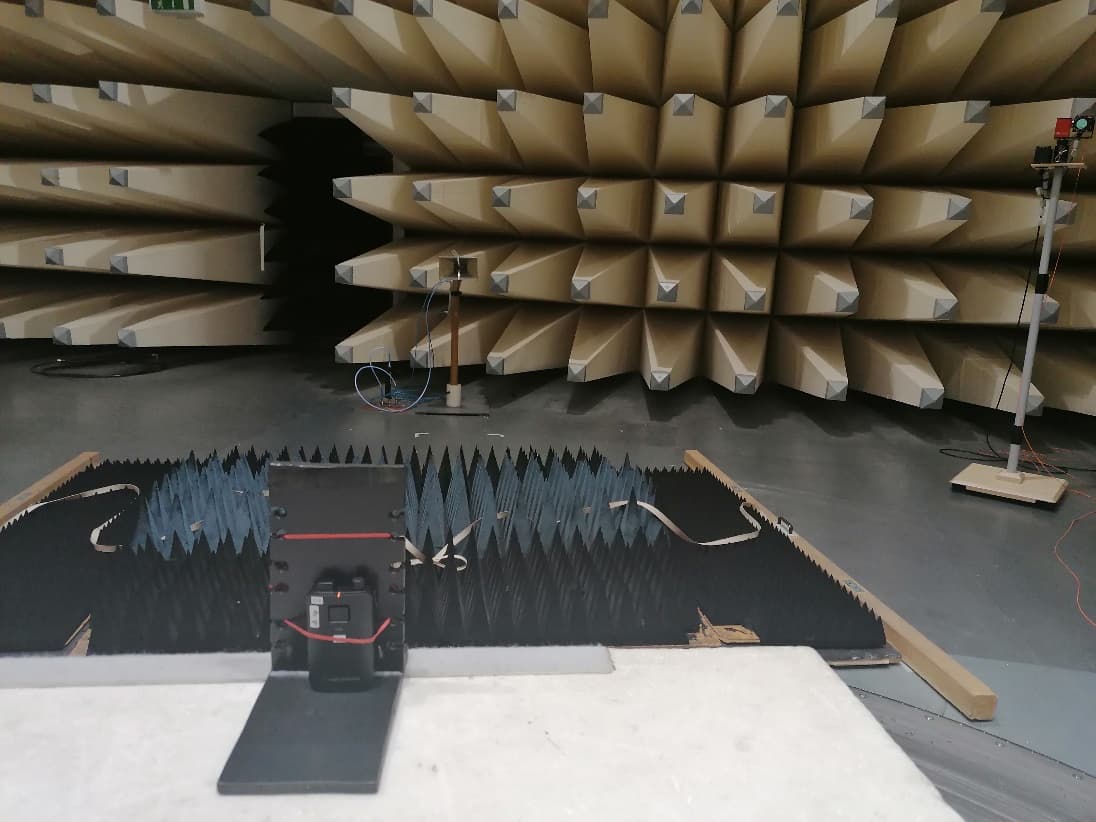
Click to zoom
Application Details
- Equipment Class
- PUT - Part 15 Unlicensed PCS portable Tx worn on body
- Date of Grant
- Mar 18, 2021
- Application Purpose
- Original Equipment
- Date of Application
- Mar 18, 2021
- Equipment Note
- Body Pack Transmitter
- Frequency Range
- 1921.53600000 - 1928.44800000
- Company
- Audio-Technica Corporation
- Country
- Japan
Documents & Files
Document Text
Text extracted from the exhibit documents filed with the FCC. Open a document above to read the original.
Users Manual
Engineered Sound Wireless Systems Quick Start Guide English ■Important information Warning: To prevent fire or shock hazard, do not expose this apparatus to rain or moisture. Caution: • Do not expose this apparatus to drips or splashes. • To avoid electric shock, do not open the cabinet. • Refer servicing to qualified personnel only. • Do not expose this apparatus to excessive heat such as sunshine, fire or the like. • Do not subject this apparatus to strong impact. • Do not place any objects filled with liquids, such as vases, on this apparatus. • To prevent fire, do not place any naked flame sources (such as lighted candles) on this apparatus. • Do not install this apparatus in a confined space such as a bookcase or similar unit. • Install this apparatus only in the place where ventilation is good. Battery caution: • Keep batteries out of the reach of children. • Observe correct polarity as marked. • Do not expose the battery to excessive heat such as sunshine, fire or the like. • Always consider the environmental issues and follow local regulations when disposing of batteries. • Remove depleted battery immediately. • Danger of explosion if battery is incorrectly replaced. Replace only with the same or equivalent type. • Do not use a leaking battery. If battery leakage occurs, avoid contact with skin. If contact occurs, immediately wash thoroughly with soap and water. • If battery leakage comes into contact with your eyes, immediately flush with water and seek medical attention. For customers in the USA FCC Notice Warning: This device complies with Part 15 of the FCC Rules. Operation is subject to the following two conditions: (1) This device may not cause harmful interference, and (2) this device must accept any interference received, including interference that may cause undesired operation. Caution: You are cautioned that any changes or modifications not expressly approved in this manual could void your authority to operate this equipment. RF Exposure Statement This device (ESW-R4180DAN) complies with FCC radiation exposure limits set forth for an uncontrolled environment and meets the FCC radio frequency (RF) Exposure Guidelines. This equipment has very low levels of RF energy that it deemed to comply without maximum permissive exposure evaluation. (MPE). But it is desirable that it should be installed and operated keeping the radiator at least 20cm or more away from person’s body. This device (ESW-T4101 / ESW-T4102/C510 / ESW-T4106 / ESW-T4107) complies with FCC radiation exposure limits set forth for an uncontrolled environment and meets the FCC radio frequency (RF) Exposure Guidelines. This equipment has very low levels of RF energy that is deemed to comply without testing of specific absorption rate (SAR). Contact: Responsible Company: Audio-Technica U.S., Inc. Address: 1221 Commerce Drive, Stow, Ohio 44224, USA Tel: 330-686-2600 For customers in Canada ISED statement This device contains licence-exempt transmitter(s)/receiver(s) that comply with Innovation, Science and Economic Development Canada’s licence-exempt RSS(s). Operation is subject to the following two conditions: 1. This device may not cause interference. 2. This device must accept any interference, including interference that may cause undesired operation of the device. This device complies with RSS-102 radiation exposure limits set forth for an uncontrolled environment. This equipment should be installed and operated with minimum distance 20cm between the radiator & your body. Français ■Informations importantes Avertissement: Pour éviter tout risque de choc électrique ou d’incendie, n’exposez pas cet appareil à la pluie ou à l’humidité. Attention: • Protégez cet appareil des projections et des gouttes d’eau. • Pour éviter tout risque de choc électrique, n’ouvrez pas le boîtier. • Confiez tous travaux d’entretien à un technicien qualifié. • N’exposez pas cet équipement à des températures excessives, telles que celles de la lumière directe du soleil, d’une flamme ou autres. • Ne soumettez pas cet équipement à de forts impacts. • Ne placez pas d’objets remplis de liquide tels que des vases, sur l’appareil. • Pour éviter tout risque d’incendie, ne placez pas de flammes nues (telles que des bougies allumées) sur l’appareil. • N’installez pas cet appareil dans un espace confiné tel qu’une étagère ou un endroit similaire. • Installez cet appareil uniquement dans des endroits avec une bonne ventilation. Mise en garde relative aux piles: • Tenez les piles hors de portée des enfants. • Respectez la polarité correcte indiquée. • N'exposez pas la pile à une chaleur excessive telle que les rayons du soleil, un feu ou autre source de chaleur. • Prenez toujours en considération l'impact environnemental et suivez les réglementations locales lors de la mise au rebut des piles. • Retirez immédiatement toute pile déchargée. • Danger d'explosion en cas de positionnement incorrect de la pile. Remplacez uniquement avec des piles de type identique ou équivalent. • N'utilisez pas une pile qui fuit. En cas de fuite de la pile, évitez tout contact avec la peau. En cas de contact, rincez aussitôt abondamment au savon et à l'eau. • Si le liquide de la pile entre en contact avec vos yeux, lavez aussitôt avec de l'eau et consultez un médecin. Pour les clients aux États-Unis Avis de la FCC Avertissement: Cet appareil est conforme à la Partie 15 du règlement de la FCC. Son fonctionnement est soumis aux deux conditions suivantes : (1) Cet appareil ne doit pas causer d’interférence nocive et (2) cet appareil doit accepter les interférences reçues, y compris les interférences pouvant provoquer un fonctionnement indésirable. Attention: Vous êtes averti que tout changement ou modification non expressément approuvé dans ce manuel est susceptible d’annuler votre droit d’utilisation de cet appareil. Déclaration d’exposition aux radiofréquences Cet appareil (ESW-R4180DAN) est conforme aux limites d’exposition concernant l’exposition aux radiations établi…
Text truncated - open the document above for the full version.
External Photos
2020-12-0 9 Page 1 of 5 Annex A: Photographs of the Test Set- up Photo 1: Radiated Emission Photo 2: Radiated Emission Test report no.: 1-1068/20-03-07 2020-12-0 9 Page 2 of 5 Annex B: External Photographs of the EUT Photo 1: Photo 2: Test report no.: 1-1068/20-03-07 2020-12-0 9 Page 3 of 5 Annex C: Internal Photographs of the EUT Photo 1: Photo 2: Test report no.: 1-1068/20-03-07 2020-12-0 9 Page 4 of 5 Photo 3: Photo 4: Test report no.: 1-1068/20-03-07 2020-12-0 9 Page 5 of 5 Photo 5:
Internal Photos
2020-12-0 9 Page 1 of 5 Annex A: Photographs of the Test Set- up Photo 1: Radiated Emission Photo 2: Radiated Emission Test report no.: 1-1068/20-03-07 2020-12-0 9 Page 2 of 5 Annex B: External Photographs of the EUT Photo 1: Photo 2: Test report no.: 1-1068/20-03-07 2020-12-0 9 Page 3 of 5 Annex C: Internal Photographs of the EUT Photo 1: Photo 2: Test report no.: 1-1068/20-03-07 2020-12-0 9 Page 4 of 5 Photo 3: Photo 4: Test report no.: 1-1068/20-03-07 2020-12-0 9 Page 5 of 5 Photo 5:
RF Exposure Info
Page 1 of 36 Annex D Appendix to Test Report No.: 1-1068/20-03-08 Testing Laboratory CTC advanced GmbH Untertürkheimer Straße 6 – 10 66117 Saarbrücken/Germany Phone: + 49 681 5 98 - 0 Fax: + 49 681 5 98 - 9075 Internet: http://www.ctcadvanced.com e-mail: [email protected] Accredited Test Laboratory: The testing laboratory (area of testing) is accredited according to DIN EN ISO/IEC 17025 (2005) by the Deutsche Akkreditierungsstelle GmbH (DAkkS) The accreditation is valid for the scope of testing procedures as stated in the accreditation certificate with the registration number: D-PL-12076-01-01 Appendix with Calibration data, Phantom certificate and system check information 2012-01-16 Test report no.: 1-1068/20-03-08 Page 2 of 36 1 Table of contents 1 Table of contents ....................................................................................................................................... 2 2 Calibration report “Probe ES3DV3” ........................................................................................................ 3 3 Calibration report “1900 MHz System validation dipole” .................................................................... 20 4 Calibration certificate of Data Acquisition Unit (DAE) ........................................................................ 28 5 Certificate of “SAM Twin Phantom V4.0/V4.0C’’ ................................................................................. 29 6 Application Note System Performance Check ..................................................................................... 30 6.1 Purpose of system performance check ..................................................................................... 30 6.2 System Performance check procedure ...................................................................................... 30 6.3 Uncertainty Budget ...................................................................................................................... 31 6.4 Power set-up for validation ......................................................................................................... 35 6.5 Laboratory reflection ................................................................................................................... 36 6.6 Additional system checks ........................................................................................................... 36 Test report no.: 1-1068/20-03-08 Page 3 of 36 2 Calibration report “Probe ES3DV3” Test report no.: 1-1068/20-03-08 Page 4 of 36 Test report no.: 1-1068/20-03-08 Page 5 of 36 Test report no.: 1-1068/20-03-08 Page 6 of 36 Test report no.: 1-1068/20-03-08 Page 7 of 36 Test report no.: 1-1068/20-03-08 Page 8 of 36 Test report no.: 1-1068/20-03-08 Page 9 of 36 Test report no.: 1-1068/20-03-08 Page 10 of 36 Test report no.: 1-1068/20-03-08 Page 11 of 36 Test report no.: 1-1068/20-03-08 Page 12 of 36 Test report no.: 1-1068/20-03-08 Page 13 of 36 Test report no.: 1-1068/20-03-08 Page 14 of 36 Test report no.: 1-1068/20-03-08 Page 15 of 36 Test report no.: 1-1068/20-03-08 Page 16 of 36 Test report no.: 1-1068/20-03-08 Page 17 of 36 Test report no.: 1-1068/20-03-08 Page 18 of 36 Test report no.: 1-1068/20-03-08 Page 19 of 36 Test report no.: 1-1068/20-03-08 Page 20 of 36 3 Calibration report “1900 MHz System validation dipole” Test report no.: 1-1068/20-03-08 Page 21 of 36 Test report no.: 1-1068/20-03-08 Page 22 of 36 Test report no.: 1-1068/20-03-08 Page 23 of 36 Test report no.: 1-1068/20-03-08 Page 24 of 36 Test report no.: 1-1068/20-03-08 Page 25 of 36 Test report no.: 1-1068/20-03-08 Page 26 of 36 Test report no.: 1-1068/20-03-08 Page 27 of 36 Test report no.: 1-1068/20-03-08 Page 28 of 36 4 Calibration certificate of Data Acquisition Unit (DAE) Test report no.: 1-1068/20-03-08 Page 29 of 36 5 Certificate of “SAM Twin Phantom V4.0/V4.0C’’ Test report no.: 1-1068/20-03-08 Page 30 of 36 6 Application Note System Performance Check 6.1 Purpose of system performance check The system performance check verifies that the system operates within its specifications. System and operator errors can be detected and corrected. It is recommended that the system performance check is performed prior to any usage of the system in order to guarantee reproducible results. The measurement of the Specific Absorption Rate (SAR) is a complicated task and the result depends on the proper functioning of many components and the correct settings of many parameters. Faulty results due to drift, failures or incorrect parameters might not be recognized, since they often look similar in distribution to the correct ones. The Dosimetric Assessment System DASY5 incorporates a system performance check procedure to test the proper functioning of the system. The system performance check uses normal SAR measurements in a simplified setup (the flat section of the SAM Twin Phantom) with a well characterized source (a matched dipole at a specified distance). This setup was selected to give a high sensitivity to all parameters that might fail or vary over time (e.g., probe, liquid parameters, and software settings) and a low sensitivity to external effects inherent in the system (e.g., positioning uncertainty of the device holder). The system performance check does not replace the calibration of the components. The accuracy of the system performance check is not sufficient for calibration purposes. It is possible to calculate the field quite accurately in this simple setup; however, due to the open field situation some factors (e.g., laboratory reflections) cannot be accounted for. Calibrations in the flat phantom are possible with transfer calibration methods, using either temperature probes or calibrated E-field probes. The system performance check also does not test the system performance for arbitrary field situations encountered during real measurements of mobile phones. These checks are performed at SPEAG by testing the components under various conditions…
Text truncated - open the document above for the full version.
RF Exposure Info
© CTC advanced GmbH Page 1 of 34 BNetzA - CAB - 02/21 - 102 D - P L - 1 2 0 7 6 - 0 1 - 0 3 TEST REPORT Test Report No.: 1-1068/20-03-08 Testing Laboratory Applicant CTC advanced GmbH Untertuerkheimer Strasse 6 – 10 66117 Saarbruecken/Germany Phone: + 49 681 5 98 - 0 Fax: + 49 681 5 98 - 9075 Internet: https://www.ctcadvanced.com e-mail: [email protected] Accredited Test Laboratory: The testing laboratory (area of testing) is accredited according to DIN EN ISO/IEC 17025 (2005) by the Deutsche Akkreditierungsstelle GmbH (DAkkS) The accreditation is valid for the scope of testing procedures as stated in the accreditation certificate with the registration number: D-PL-12076-01-03 Audio-Technica Corp. 2-46-1 Nishi-naruse, Machida 194-8666 Tokyo/JAPAN Contact: Hiroki Sato e-mail: [email protected] Phone: +81 4 27 39 91 06 34 05 Manufacturer Audio-Technica Corp. 2-46-1 Nishi-naruse, Machida 194-8666 Tokyo/JAPAN Test Standards IEEE 1528-2013 Recommended Practice for Determining the Peak Spatial-Average Specific Absorption Rate (SAR) in the Human Head from Wireless Communications Devices: Measurement Techniques RSS-102 Issue 5 Radio Frequency Exposure Compliance of Radiocommunication Apparatus (All Frequency Bands) For further applied test standards please refer to section 3 of this test report. Test Item Kind of test item: Body-Pack Transmitter Device type: portable device Model name: ESW-T4101 S/N serial number: dB 48 (US) (TF8) FCC-ID: JFZT4101 ISED Number: 1752B-T4101 Product Marketing Name (PMN): ESW-T4101 Hardware Version Identification No. (HVIN): ESW-T4101 Hardware status: TP2 Software status: V3509_3 Frequency: UPCS 1925 MHz Antenna: integrated antenna Power supply: Li-Ion battery 3.6 V / 2200 mAh Accessories: -- Test sample status: identical prototype Exposure category: general population / uncontrolled environment This test report is electronically signed and valid without handwriting signature. For verification of the electronic signatures, the public keys can be requested at the testing laboratory. Test Report authorised: Test performed: Alexander Hnatovskiy Marco Scigliano Lab Manager Testing Manager Radio Communications Radio Communications Test report no.: 1-1068/20-03-08 © CTC advanced GmbH Page 2 of 34 1 Table of contents 1 Table of contents ....................................................................................................................................... 2 2 General information .................................................................................................................................. 3 2.1 Notes and disclaimer ..................................................................................................................... 3 2.2 Application details ......................................................................................................................... 3 2.3 Statement of compliance ............................................................................................................... 3 3 Test standards/ procedures references .................................................................................................. 4 3.1 RF exposure limits ......................................................................................................................... 5 4 Summary of Measurement Results ......................................................................................................... 6 5 Test Environment ...................................................................................................................................... 6 6 Test Set-up ................................................................................................................................................. 7 6.1 Measurement system ..................................................................................................................... 7 6.1.1 System Description ................................................................................................................ 7 6.1.2 Test environment ................................................................................................................... 8 6.1.3 Probe description ................................................................................................................... 8 6.1.4 Phantom description .............................................................................................................. 9 6.1.5 Device holder description .................................................................................................... 10 6.1.6 Scanning procedure ............................................................................................................ 11 6.1.7 Comparison of DASY 52 NEO and cDASY6 ....................................................................... 15 6.1.8 Spatial Peak SAR Evaluation .............................................................................................. 16 6.1.9 Data Storage and Evaluation............................................................................................... 19 6.1.10 Tissue simulating liquids: dielectric properties .................................................................... 21 6.1.11 Tissue simulating liquids: parameters ................................................................................. 21 6.1.12 Measurement uncertainty evaluation for SAR test .............................................................. 22 6.1.13 Measurement uncertainty evaluation for System Check ..................................................... 23 6.1.14 System check ...................................................................................................................... 24 6.1.15 System check procedure ..................................................................................................... 25 6.1.16 System validation ...............................................................…
Text truncated - open the document above for the full version.
Test Report
2020-12-09 Page 1 of 56 TEST REPORT Test Report No.: 1-1068/20-03-07 Testing Laboratory Applicant CTC advanced GmbH Untertürkheimer Straße 6 – 10 66117 Saarbrücken/Germany Phone: + 49 681 5 98 - 0 Fax: + 49 681 5 98 - 9075 Internet: http://www.ctcadvanced.com e-mail: [email protected] Accredited Test Laboratory: The testing laboratory (FCC part 15 D) is accredited according to DIN EN ISO/IEC 17025 (2018) by the Deutsche Akkreditierungsstelle GmbH (DAkkS) The accreditation is valid for the scope of testing procedures as stated in the accreditation certificate with the registration number: D-PL-12076-01-04 / -05 Audio-Technica Corp. 2-46-1 Nishi-naruse, Machida 194-8666 Tokyo / Japan Phone: +81 4 27 39 91 06 34 05 Contact: Hiroki Sato e-mail: [email protected] Phone: +81 4 27 39 91 06 34 05 Manufacturer Audio-Technica Corp. 2-46-1 Nishi-naruse, Machida 194-8666 Tokyo / Japan Test Standard/s FCC Part 15, subpart D: 2016 Isochronous UPCS Device 1920 – 1930 MHz Industry Canada RSS-213, Issue 3: 2015 2 GHz Licence-exempt Personal Communication Service Devices (LE-PCS) Test Item Kind of product: Body-Pack Transmitter Product name: ESW-T4101 HVIN: PMN: FVIN: HMN: FCC ID: ESW-T4101 ESW-T4101 / / JFZT4101 IC: 1752B-T4101 S/N serial number: Radiated: / Conducted: / HW hardware status: TP2 SW software status: V3509_3 Frequency [MHz]: 1920 -1930 Type of Modulation: π/2-DBPSK, π/4-DQPSK Number of channels: 5 RF Channels, 5x12 = 60 TDMA Duplex Channels Antenna: 2 internal chip antennas Power Supply: 3.6 V DC, LiIon battery Temperature Range: -20°C to 50°C Test Report authorised: Test performed: 2020-12-09 Lenjoint, Marco 2020-12-09 Wolf, Joachim Lab Manager RCE Head of Department EPNS Test report no.: 1-1068/20-03-07 2020-12-09 Page 2 of 56 1 Table of contents 1 Table of contents ......................................................................................................................................... 2 2 General information .................................................................................................................................... 3 2.1 Notes and disclaimer ....................................................................................................................... 3 2.2 Application details ........................................................................................................................... 3 3 Test standard/s: ........................................................................................................................................... 3 4 Test Environment ........................................................................................................................................ 4 5 Summary of Measurement Results ........................................................................................................... 5 6 Test Set-up ................................................................................................................................................... 6 6.1 Frequency Measurements ............................................................................................................... 6 6.2 Timing Measurements ..................................................................................................................... 6 6.3 Conducted Emission Test ............................................................................................................... 6 6.4 Radiated Emission Test ................................................................................................................... 7 6.5 Power Line Conducted Emissions Test ......................................................................................... 9 6.6 Monitoring Tests............................................................................................................................. 10 6.7 Radiated Output Power Test ......................................................................................................... 10 7 Detailed Test Results ................................................................................................................................ 11 7.1 Power Line Conducted Emissions ............................................................................................... 11 7.2 Digital Modulation Techniques ..................................................................................................... 12 7.3 Labeling Requirements .................................................................................................................. 12 7.4 Antenna Requirements .................................................................................................................. 13 7.5 Channel Frequencies ..................................................................................................................... 13 7.6 Automatic Discontinuation of Transmission ............................................................................... 14 7.7 Peak Power Output ........................................................................................................................ 15 7.8 Emission Bandwidth B ........................................................................................................... 18 7.9 Power Spectral Density ................................................................................................................. 21 7.10 In-Band Unwanted Emissions, Conducted .............................................................................. 26 7.11 Out-of-Band Emissions, Conducted ......................................................................................... 29 7.12 Carrier Frequency Stability ........................................................................................................ 30 7.13 Frame Repetition Stability ......................................................................................................... 34 7.14 Frame Period and Ji…
Text truncated - open the document above for the full version.
Test Setup Photos
Page 1 of 5 BNetzA - CAB - 02/21 - 102 Annex C Photo documentation Appendix to Test Report No.: 1-1068/20-03-08 Testing Laboratory CTC advanced GmbH Untertürkheimer Straße 6 – 10 66117 Saarbrücken/Germany Phone: + 49 681 5 98 - 0 Fax: + 49 681 5 98 - 9075 Internet: http://www.ctcadvanced.com e-mail: [email protected] Accredited Test Laboratory: The testing laboratory (area of testing) is accredited according to DIN EN ISO/IEC 17025 (2005) by the Deutsche Akkreditierungsstelle GmbH (DAkkS) The accreditation is valid for the scope of testing procedures as stated in the accreditation certificate with the registration number: D-PL-12076-01-03 D-PL-12076-01-03 Test report no.: 1-1068/20-03-08 Page 2 of 5 Photo 1: Measurement System DASY 5 Photo 2: DUT - Front view Test report no.: 1-1068/20-03-08 Page 3 of 5 Photo 3: DUT - Topside view Photo 4: DUT - Rear view Test report no.: 1-1068/20-03-08 Page 4 of 5 Photo 5: DUT - Label Photo 6: Test position - Front with 0mm distance Test report no.: 1-1068/20-03-08 Page 5 of 5 Photo 7: Test position - Rear with 0mm distance
Test Setup Photos
2020-12-0 9 Page 1 of 5 Annex A: Photographs of the Test Set- up Photo 1: Radiated Emission Photo 2: Radiated Emission Test report no.: 1-1068/20-03-07 2020-12-0 9 Page 2 of 5 Annex B: External Photographs of the EUT Photo 1: Photo 2: Test report no.: 1-1068/20-03-07 2020-12-0 9 Page 3 of 5 Annex C: Internal Photographs of the EUT Photo 1: Photo 2: Test report no.: 1-1068/20-03-07 2020-12-0 9 Page 4 of 5 Photo 3: Photo 4: Test report no.: 1-1068/20-03-07 2020-12-0 9 Page 5 of 5 Photo 5:
Contact Information
Applicant
Fumio Kamimura(General Manager, Engineering Planning Division)
Test Firm
cetecom advanced GmbHGerald Schmidt
Technical Specifications
| # | Rule Parts | Frequency Range | Power Output | Tolerance |
|---|---|---|---|---|
| 1 | 15D | 1.92 GHz - 1.93 GHz | 120.00 mW | 1.4000000000 ppm |
Other Applications from Audio-Technica Corporation
JFZDT3207DF2
Apr 06, 2026DESK STAND TRANSMITTER
Equipment Class
DWM - Part 15 Wireless MicrophoneJFZT210CS
Jul 17, 2024UniPak Transmitter
Equipment Class
TLD - Licensed LPAS DeviceJFZT220CS
Jul 17, 2024Handheld Transmitter
Equipment Class
TLD - Licensed LPAS DeviceJFZCKS50TW2R
Jun 10, 2024Wireless Headphones
Equipment Class
DTS - Digital Transmission SystemJFZCKS30TWPR
Apr 02, 2024Wireless Headphones
Equipment Class
DSS - Part 15 Spread Spectrum Transmitter