JFZT5000CWireless Microphone Transmitter
Audio-Technica Corporation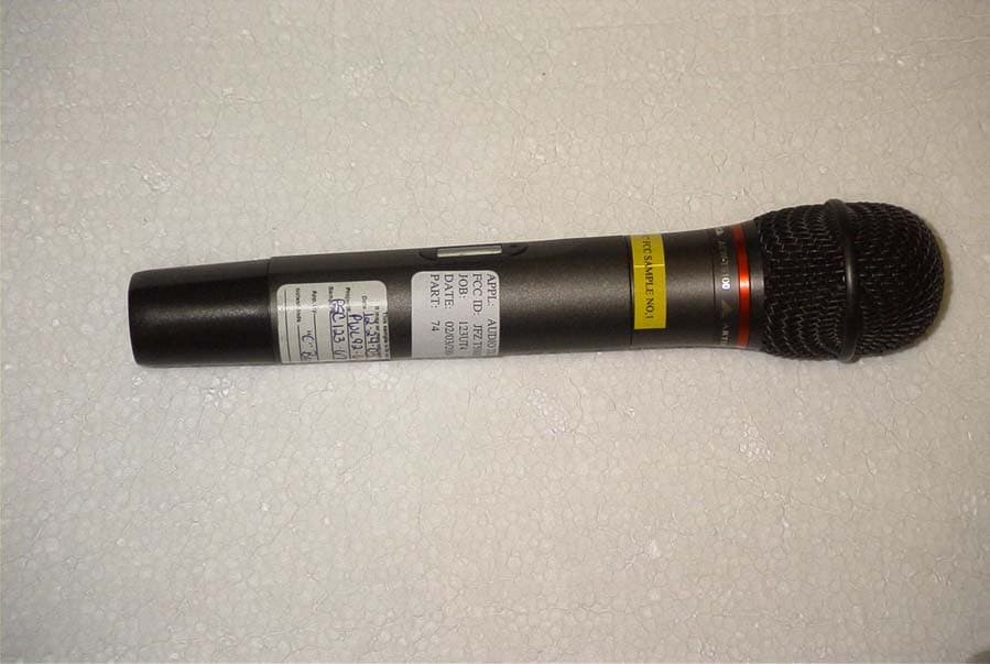
Click to zoom
Application Details
- Equipment Class
- TBF - Licensed Broadcast Transmitter Held to Face
- Date of Grant
- Mar 15, 2004
- Application Purpose
- Original Equipment
- Date of Application
- Mar 15, 2004
- Equipment Note
- Wireless Microphone Transmitter
- Frequency Range
- 541.50000000 - 566.37500000
- Company
- Audio-Technica Corporation
- Country
- Japan
Documents & Files
Document Text
Text extracted from the exhibit documents filed with the FCC. Open a document above to read the original.
Users Manual
AUDIO TECHNICA MODEL AEW-5200, AEW-4100 SERIES UHF WIRELESS SYSTEM USER INFORMATION. INTRODUCTION Thank you for purchasing the AEW-5200, AEW-4100 series wireless system. It is our hope that the system will bring you years of trouble free pleasure and performance. Please follow the information contained in this manual closely as it will assist you in using your equipment effectively. PART1. REGULATORY REQUIREMENTS. FCC PART 15 COMPLIANCE STATEMENT CANADA RSS-210 COMPLIANCE STATEMENT “This device complies with Part 15 of the FCC rules. Operation is subject to the condition that this device does not cause harmful interference” “This device complies with INDUSTRY CANADA R.S.S. 210, en confomite avec IC: RSS-210/CNR210. Operation is subject to the following conditions: (1) This device may not cause harmful interference and (2) This device must accept any interference received, including interference which may cause undesired operation.” Please note that your AEW-5200, AEW-4100 systems operates in a frequency band in a way which may make its use subject to certain FCC and other regulatory agency restrictions and licensing requirements. For further information, Please contact your local office of the FCC as applicable. NOTE: THE MANUFACTURER IS NOT RESPONSIBLE FOR ANY RADIO OR TV INTERFERENCE CAUSED BY UNAUTHORIZED MODIFICATIONS TO THIS EQUIPMENT. SUCH MODIFICATIONS COULD VOID THE USER'S AUTHORITY TO OPERATE THE EQUIPMENT. PART 2. USING THE AEW-T1000 BELTPACK TRANSMITTER The beltpack transmitter operates on 2 “AA” batteries. Please make sure that your batteries are fresh. We recommend that you use Alkaline batteries and that you avoid using NiCad if possible. Open the battery door by slide door lock towards arrow direction and lift door. Insert two batteries into the battery compartment and close the battery door Slides the LCD set up buttons cover down to bottom Push and hold the power switch and turn the AEW-T1000 on Push the set button once Using up or down arrow buttons and scrolls the menu until frequency menu appeared. If current frequency setup appeared on the LCD is not the same as corresponding receiver frequency, push set button once. Push down or up arrow button and set frequency to the corresponding frequency as set on receiver. Push and hold set button until word “Stored” displayed in a while. Push up or down arrow button and scrolls the menu until input menu (MIC or INSTRUMENT) appeared. If current input setup appeared on LCD screen is not correct, push set button once Using up or down arrow button to select input. Push and hold set button until word “Stored” displayed in a while. Connect your microphone or guitar cable to the connector on the top of the transmitter. Confirm that the receiver is receiving RF and the audio is passing through the receiver. Push up or down arrow button and scrolls the menu until “ESCAPE” appeared. Push the set button once to return default menu. You are now ready to use the system. PART 3. USING THE AEW-T5000SERIES HANDHELD TRANSMITTER AEW-T5000 transmitter family is as follows: AEW-T5400 AEW-T3300 AEW-T6100 AEW-T4100 The handheld transmitter operates on 2 “AA” batteries. Please make sure that your batteries are fresh. We recommend that you use Alkaline batteries and that you avoid using NiCad if possible. Hold the bottom grip and turn the top grip counter clockwise until bottom grip free to slide. Slide the bottom grip, insert two batteries into the battery compartment and slide the battery compartment back into place. To change the frequency of operation, push and hold the power /mute button located on bottom of the transmitter to turn it on. Unscrew the battery cover and pull the cover back. Push the set button once Using up or down arrow button and scrolls the menu until frequency menu appeared. Push the set button once. Push down or up arrow button and set frequency to the corresponding frequency as set on receiver. Push and hold set button until word “Stored” displayed in a while. Push up or down arrow button and scrolls the menu until “ESCAPE” appeared Push the set button once to return default menu You are now set to use the system. PART4. USING THE AEW-R5200, AEW-R4100 RECEIVERS Plug the IEC plug on the AC cable to the AC inlet on back of the receiver. Plug the 3-pin AC plug on AC cable to an 110V AC outlet. Connect two antennas to the antenna input on back of the receiver. Push the Power switch. Confirm that the backlight on LCD screen comes on. Check the frequency setting to confirm that they correspond to the settings of the transmitter If not, push set button once to display “FREQ” on top line of the LCD. Push set button once and check that “EDIT” displayed on bottom line of LCD brink. Push up or down arrow button to set receiver frequency to corresponding transmitter frequency. Push and hold set button until “STORED” displayed in a while. Push up or down arrow button to display “QUIT” Push Set button once to back in to Default menu. Connect the balanced or unbalanced audio output to your mixer or PA system. Adjust the Volume setting to the desired level. Speak into the microphone and listen to the audio out at the speaker. If satisfied with the audio quality, you ca uses the system.
Cover Letter(s)
Audio-Technica U.S., Inc. 1221 Commerce Drive Phone: 330-686-2600 [email protected] Stow, OH 44224-1760 Fax: 330-688-3752 January 26, 2004 Equipment Authorization Division Office of Engineering and Technology Federal Communications Commission 7435 Oakland Mills Road Columbia, MD 21046 Ref: FCC ID: JFZT5000C Request for Confidentiality Dear Sirs: With regard to the referenced application, Audio Technica, is requesting confidentiality of certain sections of the accompanying documents. The documents for which Audio Technica is requesting confidentiality are: Schematic for AEW-T5000C wireless transmitter Block diagram for AEW-T5000C wireless transmitter Circuit description for AEW-T5000C wireless transmitter This request is made under the provisions of Section 0.457(d) of the Commission’s Rules, and Section 552(b)(4) of the Freedom of Information Act. The material for which confidentiality is requested falls within the scope of Section 552(b)(4) as trade secrets and includes material covered by Section 0.459 of the Commission’s Rules. Sincerely, Jacquelynn Green Vice President R&D Audio-Technica U.S., Inc.
ID Label/Location Info
FREQ. : 54 1-566MHz AEW-T5000 FCC ID : JFZT5000C IC : 1752B-AEW5000C
Parts List/Tune Up Info
ATW-T5000 Transmitter Electronic Parts List INTEGRATED CIRCUIT Ref,No Parts Name PackageNote IC1 NJM2068MD SMT 8pin IC2 DREAMT-1 SMT 64pin IC3 SA572D SMT 16pin IC4 MB89P165 SMT 80pin IC5 MB1511PFV SMT 16pin IC6 XC61CN4002NR SMT 4pin IC7 S-93C46AMFN SMT 8pin IC8 NJU6366DF SMT 6pin IC501 LTC3401EMS SMT 10pin DISPLAY Ref,No Parts Name PackageNote TX-LCD TRANSISTOR Ref,No Parts Name Package Note Q300 2SC4738Y SMT 3pin Q301 UPA604T SMT 6pin Q303 2SC4226 SMT 3pin Q304 2SC5226 SMT 3pin Q305 2SC5226 SMT 3pin Q306 2SC5226 SMT 3pin Q307 2SC5226 SMT 3pin Q308 2SC4738Y SMT 3pin Q309 2SC4738Y SMT 3pin Q310 2SA1745 SMT 3pin Q311 DTA114YE SMT 3pin Q501 2SC4738Y SMT 3pin Q502 CPH3106 SMT 3pin Q503 2SC3324 SMT 3pin DIODES & LED Ref,No Parts Name Package Note D1 NNCD6.2C SMT 2pin D2 NNCD6.2C SMT 2pin D3 NNCD6.2C SMT 2pin D4 NNCD12C SMT 2pin D14 HSC119 SMT 2pin D15 SLC-9D126A SMT 2pin D101 1SS302 SMT 3pin D102 1SS302 SMT 3pin D103 NNCD12C SMT 2pin D201 NNCD6.2C SMT 2pin D202 NNCD6.2C SMT 2pin D206 NNCD6.2C SMT 2pin D301 HSC119 SMT 2pin D501 NNCD6.2C SMT 2pin D502 DCG010 SMT 3pin D503 NNCD6.2C SMT 2pin D504 NNCD6.2C SMT 2pin D505 DCG010 SMT 3pin D506 SL12 SMT 2pin D507 NNCD6.2C SMT 2pin D508 HRC0103ATRF SMT 2pin D509 HRC0103ATRF SMT 2pin INDUCTOR & COIL Ref,No Parts Name Package L1 LK16081R0K SMT 2pin L2 LK16081R0K SMT 2pin L3 LK16081R0K SMT 2pin L4 LK16081R0K SMT 2pin L5 LK10052R2K SMT 2pin L8 LK10052R2K SMT 2pin L9 LK10052R2K SMT 2pin L10 LK10052R2K SMT 2pin L101 LK10052R2K SMT 2pin L102 LK10052R2K SMT 2pin L301 LL1608-FSR10J SMT 2pin L302 LQN21A33NJ04 SMT 2pin L303 LQN21A12NJ04 SMT 2pin L304 LQN21A15NJ04 SMT 2pin L305 LQN21A15NJ04 SMT 2pin L306 LQN21A12NJ04 SMT 2pin L307 LL1608-FSR10J SMT 2pin L308 LK16081R0K SMT 2pin L310 LK16081R0K SMT 2pin L501 CDRH6D38-100 SMT 2pin L502 LEMF2520-100K SMT 2pin L503 LEMF2520-100K SMT 2pin SWITCH Ref,No Parts Name Package SW207 SKQMBA SMT 2pin SW208 SKQMBA SMT 2pin SW209 SKQMBA SMT 2pin SW501 SKHLLC LEAD 4pin VARIABLE CAPACITOR Ref,No Parts Name Package TC301 TC13C100C-TP03 SMT 2pin TC302 TC13C060C-TP03 SMT 2pin CRYSTAL Ref,No Parts Name Package X301 9.00MHz LEAD 2pin V C O Ref,No Parts Name Package VCO1 554M SMT JACK PLUG & CONNECTOR Ref,No Parts Name Package CN2 52330-0417 LEAD CN301 MM7329-2700 SMT CN302 XX-2 POTENTIOMETER Ref,No Parts Name Package VR3 RH02B1C14X SMT 3pin VR4 RH02B1C15X SMT 3pin VR201 RH02B1CS5X SMT 3pin VR300 RH02B1CJ4X SMT 3pin VR301 RH02B1CJ4X SMT 3pin CAPACITOR Ref,No Parts Name Package Note C1 100p/50V SMT Ceramic C2 10uF/16V SMT Tantalum C3 1uF/16V SMT Tantalum C4 1uF/16V SMT Tantalum C10 0.01uF/16V SMT Ceramic C11 10uF/6.3V SMT Tantalum C18 100pF/50V SMT Ceramic C19 100pF/50V SMT Ceramic C33 0.01uF/16V SMT Film C34 470pF/50V SMT Ceramic C35 2.2uF/10V SMT Tantalum C36 820pF/50V SMT Ceramic C37 470pF/50V SMT Ceramic C38 56pF/50V SMT Ceramic C39 2.2uF/10V SMT Tantalum C42 10uF/6.3V SMT Tantalum C43 0.01uF/16V SMT Ceramic C44 2.2uF/10V SMT Tantalum C45 2200pF/50V SMT Ceramic C46 470pF/50V SMT Ceramic C49 10uF/6.3V SMT Tantalum C50 0.01uF/16V SMT Ceramic C51 2.2uF/10V SMT Tantalum C52 1uF/16V SMT Tantalum C54 22pF/50V SMT Ceramic C100 2.2uF/10V SMT Tantalum C101 2.2uF/10V SMT Tantalum C102 4700p/16V SMT Film C103 220pF/50V SMT Ceramic C104 0.1uF/10V SMT Ceramic C105 56pF/50V SMT Ceramic C106 10uF/6.3V SMT Tantalum C107 10uF/16V SMT Tantalum C108 0.01uF/16V SMT Ceramic C109 0.047uF/16V SMT Film C110 0.1uF/16V SMT Film C111 0.47uF/16V SMT Tantalum C112 10uF/6.3V SMT Tantalum C113 4.7uF/10V SMT Tantalum C115 4.7uF/10V SMT Tantalum C116 1uF/16V SMT Tantalum C117 1uF/16V SMT Tantalum C118 1uF/16V SMT Tantalum C119 2.2uF/10V SMT Tantalum C120 0.1uF/25V SMT Ceramic C121 0.47uF/16V SMT Tantalum C122 0.01uF/16V SMT Ceramic C123 0.01uF/16V SMT Ceramic C201 0.01uF/16V SMT Ceramic C202 10uF/6.3V SMT Tantalum C203 0.01uF/16V SMT Ceramic C204 10uF/6.3V SMT Ceramic C206 4.7uF/10V SMT Tantalum C207 0.01uF/16V SMT Ceramic C208 10uF/6.3V SMT Tantalum C300 100pF/50V SMT Ceramic C301 10uF/6.3V SMT Tantalum C305 10p/50V SMT Ceramic C306 100pF/50V SMT Ceramic C307 0.47uF/16V SMT Tantalum C308 10uF/6.3V SMT Tantalum C309 0.01uF/16V SMT Ceramic C310 0.01uF/16V SMT Ceramic C311 100p/50V SMT Ceramic C312 47uF/6.3V SMT Tantalum C313 100p/50V SMT Ceramic C314 100p/50V SMT Ceramic C315 100p/50V SMT Ceramic C316 6p/50V SMT Ceramic C317 47uF/6.3V SMT Tantalum C318 2p/50V SMT Ceramic C319 100p/50V SMT Ceramic C320 100p/50V SMT Ceramic C321 100p/50V SMT Ceramic C322 6p/50V SMT Ceramic C323 100p/50V SMT Ceramic C324 100p/50V SMT Ceramic C325 100p/50V SMT Ceramic C326 100p/50V SMT Ceramic C328 2.2uF/10V SMT Tantalum C329 2p/50V SMT Ceramic C330 6p/50V SMT Ceramic C331 6p/50V SMT Ceramic C332 6p/50V SMT Ceramic C333 6p/50V SMT Ceramic C334 3p/50V SMT Ceramic C335 100p/50V SMT Ceramic C336 47uF/6.3V SMT Tantalum C337 100p/50V SMT Ceramic C351 0.01uF/16V SMT Ceramic C353 100p/50V SMT Ceramic C354 47uF/6.3V SMT Tantalum C355 100p/50V SMT Ceramic C356 100p/50V SMT Ceramic C357 1000pF/50V SMT Ceramic C358 10uF/6.3V SMT Tantalum C359 100p/50V SMT Ceramic C361 1000pF/50V SMT Ceramic C501 0.01uF/16V SMT Ceramic C503 10uF/6.3V SMT POS CAP C504 47uF/6.3V SMT Tantalum C505 3300p/50V SMT Ceramic C506 100p/50V SMT Ceramic C507 10uF/6.3V SMT POS CAP C508 10uF/6.3V SMT POS CAP C509 10uF/6.3V SMT POS CAP C510 10uF/6.3V SMT Tantalum C511 10uF/16V SMT Tantalum C512 22uF/16V SMT Tantalum C513 10uF/16V SMT Tantalum C514 0.1uF/10V SMT Ceramic C521 0.1uF/10V SMT Ceramic C522 0.1uF/10V SMT Ceramic C524 10uF/6.3V SMT POS CAP C525 0.1uF/10V SMT Ceramic C526 10uF/16V SMT Tantalum C527 1000pF/50V SMT Ceramic C528 1000pF/50V SMT Ceramic C529 100p/50V SMT Ceramic C530 100p/50V SMT Ceramic C532 0.1uF/25V SMT Ceramic C533 0.1uF/25V SMT Ceramic C534 0.1uF/10V SMT Ceramic C535 100p/50V SMT Ceramic C536 100p/50V SMT Ceramic C537 100p/50V SMT Ceramic C538 100p/50V SMT Ceramic C601 1000pF/50V SMT Ceramic C602 1000pF/50V SMT Ceramic C603 1000pF/50V SMT Ceramic C604 100p/50V SMT Ceramic C605 100p/50V SMT Ceramic RESISTOR…
Text truncated - open the document above for the full version.
Parts List/Tune Up Info
Subsection 2.983(d)(9): Factory Tune-up Procedure Test Equipment 1. BNC-P to MM121454 Coaxial RF cable Audio Technica custom RF cable 2. DC Power Supply Leader LPS-160-2 3. Audio Signal Generator Leader LAG-126S 4. Modulation Meter (FM liner detector) Anritsu MS61A 5. Spectrum Analyzer Advantest R3361D 6. RF Power Meter Anritsu MS 4803A 7. RF Power Sensor Anritsu MA4701A 8. Oscilloscope Tektronix 475A 9. DC Volt Meter Fluke 79 10. AC milli Volt Meter Leader LMV-1817 Adjustment of T5000 Main circuit board 1. Adjusting the frequency: 1-1. Setting of the measurement equipment and T5000C a. Setting of Spectrum Analyzer - Center frequency: 554.00 MHz - Frequency span: 200kHz - Counter mode: ON b. Setting of LCD for T5000C - Frequency: 554.000MHz - RF-POWER: HI - GAIN: -6dB 1-2. Frequency set up: a. Adjust the T5000C carrier frequency by rotating the TC301 on the PCB of T5000C b. Set the main carrier peak of to the spectrum analyzer’s center frequency. 2. Adjusting Carrier Peak: 2-1. Setting of measurement equipment and T5000C hba. Setting of Spectrum Analyzer - Center Frequency: 554.000MHz - Frequency Span: 200kHz - Counter Mode: OFF b. Setting of T5000C - Same as 1-1-b 2-2. Adjustment of T5000C a. Adjusts the TC302 on PCB of T5000C and set the main carrier to have peak. 3. Adjustment of RF Power: 3-1. Setting of measurement equipment and T5000C a. Setting of RF Power meter - Measurement range: Auto-mode b. Setting of T5000C - Frequency: 554.000MHz - RF-POWER HI & LOW - GAIN -6dB 3-2. Adjustment of T5000C a. Adjust the RF output power by rotating the VR301 on PCB of T5000C and set VR301 to have RF power meter at 35mW b. Adjust the LCD POWER of T5000C to LOW. c. Adjust and set the VR300 to have RF power meter at 10mW. 4. Adjustment of deviation 4-1. Setting of measurement equipment and T5000C a. Setting of Deviation Meter - Sensitivity: P-P/2 - Measurement Range: 100kHz - HPF: 50Hz - LPF: 20kHz - Measurement Frequency: 554.000MHz b. Input Audio Signal (Apply to CN2) - Frequency: 1kHz - Signal level: +4dBV (CN2 terminal voltage) c. Setting of T5000C - Same as 1-1-b 4-2. Adjusting T5000C a. Adjust and set the VR3 on PCB of T5000C to have deviation meter to set +/-40kHz. 5. Adjustment of Tone Deviation 5-1. Setting of measurement equipment and T5000C a. Setting of Deviation Meter - Sense: P-P/2 - Measurement range: 3kHz - HPF: 4kHz - LPF: 120kHz - Measurement frequency: 554.000MHz b. Setting of T5000C - Same as 1-1-b 5-2. Adjustment of T5000C a. Adjust the tone signal modulation level by rotating the VR4 on PCB of T5000C and set the VR4 to have the deviation meter to set +/-2kHz.
Test Report
TIMCO ENGINEERING INC. 849 NW State Road 45 Newberry, Florida 32669 http://www.timcoengr.com 888.472.2424 F 352.472.2030 email: [email protected] APPLICANT: AUDIO TECHNICA CORPORATION Test Report Product Name: WIRELESS MICROPHONE FCC ID: JFZT5000C Applicant: AUDIO TECHNICA CORPORATION 2206 NARUSE MACHIDA TOKYO 194 JAPAN Date Receipt: FEBRUARY 3, 2004 Date Tested: FEBRUARY 26, 2004 FCC ID: JFZT5000C REPORT #: T:\A\AudioTechnica_JFZ\123UT4\123UT4TestReport.doc COVER SHEET TIMCO ENGINEERING INC. 849 NW State Road 45 Newberry, Florida 32669 http://www.timcoengr.com 888.472.2424 F 352.472.2030 email: [email protected] APPLICANT: AUDIO TECHNICA CORPORATION APPLICANT: AUDIO TECHNICA CORPORATION FCC ID: JFZT5000C TABLE OF CONTENTS LIST TEST REPORT CONTAINING: PAGE 1............GENERAL INFORMATION & TECHNICAL DESCRIPTION PAGE 2............TECHNICAL DESCRIPTION & RF OUTPUT POWER PAGE 3............MODULATION CHARACTERISTICS AUDIO FREQUENCY RESPONSE GRAPH PAGE 4............AUDIO INPUT VERSUS MODULATION GRAPH PAGE 5............OCCUPIED BANDWIDTH PAGE 6............OCCUPIED BANDWIDTH PLOT PAGE 7-9..........RADIATED EMISSIONS TEST DATA PAGE 10...........METHOD OF MEASURING RADIATED SPURIOUS EMISSIONS PAGE 11...........FREQUENCY STABILITY TEST DATA PAGE 12-13........EQUIPMENT LIST EXHIBITS CONTAINING: CONFIDENTIALITY LETTER BLOCK DIAGRAM SCHEMATICS PARTS LIST USERS MANUAL LABEL SAMPLE LABEL LOCATION EXTERNAL PHOTOGRAPHS INTERNAL PHOTOGRAPHS ALIGNMENT PROCEDURE OPERATIONAL DESCRIPTION TEST SET UP PHOTOGRAPH FCC ID: JFZT5000C REPORT #: T:\A\AudioTechnica_JFZ\123UT4\123UT4TestReport.doc TABLE OF CONTENTS TIMCO ENGINEERING INC. 849 NW State Road 45 Newberry, Florida 32669 http://www.timcoengr.com 888.472.2424 F 352.472.2030 email: [email protected] APPLICANT: AUDIO TECHNICA CORPORATION GENERAL INFORMATION REQUIRED FOR TYPE ACCEPTANCE 2.1033(c)(1)(2) AUDIO TECHNICA CORPORATION will manufacture the T5000C in quantity, for use under FCC RULES PART 74.801, LOW POWER AUXILIARY STATIONS. AUDIO TECHNICA CORPORATION 2206 NARUSE, MACHIDA TOKYO, 194 JAPAN 2.1033 TECHNICAL DESCRIPTION (3) Instruction book. The instruction manual is included in the exhibits. (4) Type of Emission: 120K0F3E Bn = 2M + 2DK M = 15000 D = 45kHz(Peak Deviation) K = 1 Bn = 2(15k) + 2(45k)(1) = 120k ALLOWED AUTHORIZED BANDWIDTH = 200kHz. (5) Frequency Range: Part 74: 541.50 – 566.375 MHz (6) Power Range and Controls: UNIT has no controls. (7) Maximum Output Power Rating: .010 Watts into 50 ohms resistive load. (8) DC Voltages and Current into Final Amplifier: FINAL AMPLIFIER ONLY 3.0V BATTERY Vce = 3.0 Volts Ice = 0.16 mA. Pin = 0.48 (9) Tune-up procedure. The tune-up procedure is given in the exhibits. (10) Complete Circuit Diagrams: The circuit diagram and block diagram are included in the exhibits. FCC ID: JFZT5000C REPORT #: T:\A\AudioTechnica_JFZ\123UT4\123UT4TestReport.doc Page 1 of 13 TIMCO ENGINEERING INC. 849 NW State Road 45 Newberry, Florida 32669 http://www.timcoengr.com 888.472.2424 F 352.472.2030 email: [email protected] APPLICANT: AUDIO TECHNICA CORPORATION 2.1033(c)(11) Photo or Drawing of Label and sketch of location: See the exhibits. 2.1033(c)(12) Photos of Equipment: See the exhibits. (13) Description of all circuitry and devices provided for determining and stabilizing frequency. Description of any circuits or devices employed for suppression of spurious radiation, for limiting modulation, and for limiting power. This circuit description is included in the exhibits. Limiting Modulation: The transmitter audio circuitry is contained in IC101, IC102 and IC103. Limiting Power: There is no provision for limiting power. (14) Digital modulation. This unit does not use digital modulation. 2.1033(c)(15) The data required by 2.1046 through 2.1057 is submitted below. 2.1046 RF power output RF power measured is: OUTPUT POWER: .010 WATTS CONDUCTED R.F. POWER OUTPUT TEST PROCEDURE Transmitter 50 ohm under test Watt Meter Audio Oscillator FCC ID: JFZT5000C REPORT #: T:\A\AudioTechnica_JFZ\123UT4\123UT4TestReport.doc Page 2 of 13 TIMCO ENGINEERING INC. 849 NW State Road 45 Newberry, Florida 32669 http://www.timcoengr.com 888.472.2424 F 352.472.2030 email: [email protected] APPLICANT: AUDIO TECHNICA CORPORATION 2.1047(a)(b) Modulation characteristics: AUDIO FREQUENCY RESPONSE The audio frequency response was measured in accordance with TIA/EIA Specification 603. The audio frequency response curve is shown below. Audio Frequency Response Plot -2 +8 -0 +2 +4 +6 d B 100 20k 200 500 1k 2k 5k 10k Hz AUDIO LOW PASS FILTER The audio low pass filter is not required in this unit. FCC ID: JFZT5000C REPORT #: T:\A\AudioTechnica_JFZ\123UT4\123UT4TestReport.doc Page 3 of 13 TIMCO ENGINEERING INC. 849 NW State Road 45 Newberry, Florida 32669 http://www.timcoengr.com 888.472.2424 F 352.472.2030 email: [email protected] APPLICANT: AUDIO TECHNICA CORPORATION 2.1047(b) Audio_input_versus_modulation 74.249 (d) A plot of the audio input versus deviation is shown below. Modulation Limiting Plots: 15.0 KHz (Cyan), 2.5 KHz (Green), 1.0 KHz (Blue), and 300 Hz (Red) 0 45 k H z -25 +20-20 -15-10-5+0+5+10 +15 dBu FCC ID: JFZT5000C REPORT #: T:\A\AudioTechnica_JFZ\123UT4\123UT4TestReport.doc Page 4 of 13 TIMCO ENGINEERING INC. 849 NW State Road 45 Newberry, Florida 32669 http://www.timcoengr.com 888.472.2424 F 352.472.2030 email: [email protected] APPLICANT: AUDIO TECHNICA CORPORATION 2.1049(c) Occupied Bandwidth: Data in the plots show that all sidebands between 50 & 100% for the authorized bandwidth are attenuated by at least 25dB. From 100 to 250% of the authorize3d bandwidth they are attenuated by at least 35dB and beyond 250% 43 log(Po) dB. The plot shows the transmitter modulated with 15000 Hz(the highest modulation frequency), adjusted for 50% modulation plus 16 dB. The spectrum analyzer was set with the un-modulated carrier at the top of the screen. The test procedure diagram and occupied bandwidth plots follow. Wireless Microphone transmitter: Test procedure d…
Text truncated - open the document above for the full version.
Contact Information
Applicant
Fumio Kamimura(General Manager, Engineering Planning Division)
Test Firm
Timco Engineering, Inc.S Sanders
Technical Specifications
| # | Rule Parts | Frequency Range | Power Output | Emission | Tolerance |
|---|---|---|---|---|---|
| 1 | 74.861 | 541.5 MHz - 566.375 MHz | 10.00 mW | 120KF3E | 50.0000000000 ppm |
Other Applications from Audio-Technica Corporation
JFZDT3207DF2
Apr 06, 2026DESK STAND TRANSMITTER
Equipment Class
DWM - Part 15 Wireless MicrophoneJFZT210CS
Jul 17, 2024UniPak Transmitter
Equipment Class
TLD - Licensed LPAS DeviceJFZT220CS
Jul 17, 2024Handheld Transmitter
Equipment Class
TLD - Licensed LPAS DeviceJFZCKS50TW2R
Jun 10, 2024Wireless Headphones
Equipment Class
DTS - Digital Transmission SystemJFZCKS30TWPR
Apr 02, 2024Wireless Headphones
Equipment Class
DSS - Part 15 Spread Spectrum Transmitter