JFZT6001SUHF SYNTHESIZED WIRELESS TRANSMITTER
Audio-Technica Corporation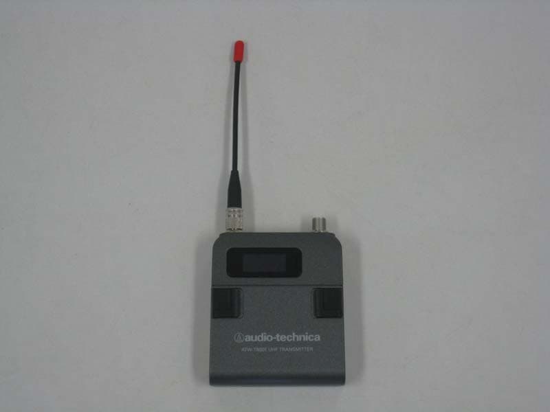
Click to zoom
Application Details
- Equipment Class
- TBT - Licensed Broadcast Transmitter Worn on Body
- Date of Grant
- Nov 14, 2015
- Application Purpose
- Original Equipment
- Date of Application
- Nov 14, 2015
- Equipment Note
- UHF SYNTHESIZED WIRELESS TRANSMITTER
- Frequency Range
- 946.12500000 - 949.87500000
- Company
- Audio-Technica Corporation
- Country
- Japan
Documents & Files
Document Text
Text extracted from the exhibit documents filed with the FCC. Open a document above to read the original.
Users Manual
User Manual UHF SYNTHESIZED WIRELESS TRANSMITTER ATW-T6001 S Thank you for purchasing the product. Before using the product, take time to read this user manual thoroughly and use the product correctly. Keep this user manual handy together with the warranty so that it is always available for reference. 2 Features 2 Important information 3 Notes on use 4 When using multiple wireless systems 4 Part names and functions 5 How to insert batteries 6 About display 7 About settings 8 Menu screen 8 Transmission frequency setting 9 NAME setting 9 To correct characters 10 Transmission power setting 10 Gain setting 10 Key lock setting 10 Lock code setting 11 Battery setting 11 Using the key lock function 12 Setting up the key lock function 12 Cancelling the key lock function 12 About IR link 12 How to attach to body 13 Troubleshooting 13 Specifications 14 Contents Simultaneous 31-band transmission IR Link feature for easy transmitter configuration A highly reliable, uniquely designed miniature microphone connector Lever push switch for improved controllability UHF band transmitter for wireless systems resistant to the effects of extraneous noise Great for stage use in live concerts, events, and the like Employs PLL synthesizer method Greater dynamic range and lower noise thanks to a double compandor (voice compression/ expansion) system (PAT.) Organic EL display for enhanced visibility Cover to prevent accidental operations Flexible 1/4 wavelength whip antenna with broad operating range Features 3 Important information Warning: To prevent fire or shock hazard, do not expose this apparatus to rain or moisture. Caution: Do not expose this apparatus to drips or splashes. To avoid electric shock, do not open the cabinet. Refer servicing to qualified personnel only. Do not expose this apparatus to excessive heat such as sunshine, fire or the like. Do not subject this apparatus to strong impact. FCC Notice Warning: Changes or modifications not expressly approved in writing by Audio- Technica may void the user’s authority to operate this equipment. RF Exposure Statement: This transmitter must not be co-located or operated in conjunction with any other antenna or transmitter used in other systems. No userserviceable parts inside. The circuits inside the chassis, transmitters have been precisely adjusted for optimum performance and compliance with federal regulations. Do not attempt to open the chassis, transmitters. To do so will void the warranty, and may cause improper operation. Batteries caution Keep batteries out of the reach of children. Observe correct polarity as marked. Do not expose the battery to excessive heat such as sunshine, fire or the like. Always consider the environment issues and follow local regulations when disposing of batteries. Remove depleted battery immediately. Danger of explosion if battery is incorrectly replaced. Replace only with the same or equivalent type. Do not use new batteries and old one at the same time. Do not use different batteries type or model. Do not use a leaking battery. If battery leakage occurs, avoid contact with skin. If contact occurs, immediately wash thoroughly with soap and water. If battery leakage comes into contact with your eyes, immediately flush with water and seek medical. 4 Be sure to read the operation manual for the connected device before use. If you use the product close to an electronic device or communications device (such as mobile phone), noise may be caused in the product. If this happens, keep it away from such devices. When setting up the product, make sure there are no obstacles between the product and receiver that will block the signal. If you use the product near a TV or radio antenna, noise may be caused in the television or radio. If this happens, keep it away from the television or radio. To prevent the batteries from wearing out, turn off the receiver power after use or when the product is not in use. If the product is used for a long period of time, discoloration may occur due to ultraviolet rays (especially direct sunlight) and friction. Any alteration or modification of this product is prohibited by law. Also, disassembly of this precision product may result in electrical shock, equipment damage or fire. Never disassemble this product. If using multiple units in the same location, keep 80 cm or more between individual transmitters and 3 m or more between transmitters and receivers. When using multiple units, turn on the transmitters one by one, making sure there is no noise. When using multiple wireless systems Notes on use 5 LR6 / AA / LR6 / AA / BACKSYNC ON OFF FREQ. : 946-950 MHz FCC ID: JF Z T6 0 01S BATT.: LR6, AA 2, 3 V Audio-Technica Corp. MADE IN JAPAN AT W-T6001 S Part names and functions Front Transmission antenna Display Shows the current status. * If no buttons are pressed for a period of 20 seconds, the display will turn off. BACK button Returns to the previous operation. SYNC button Use for IR Link with a receiver. Lever push switch Used for selecting various settings. UP ( ) Turn to the right to change a selection. DOWN ( ) Turn to the left to change a selection. SET ( ) Press to confirm a selection. * For details on how to operate, see "About settings". Input connector Connect a microphone (optional). Power switch Turns the power on/off. Power indicator Lights in green when the power is on. Lights in red when battery power is low. Recall button Turns the screen back on if the screen is off. To p Rear IR receiving part This is the receiving part for IR link. 6 How to insert batteries 1. Slide the battery cover nob toward the inside. 2. From that position, slide the nob in the direction shown by the arrow 3. Then, open the battery cover as shown in the diagram. 4. Insert the batteries correctly according to the plus (+) and minus (-) marks indicated on the product. 7 The main screen is displayed when the power is switched on. 946. 125MHz Frequency/NAME Press UP/DOWN to switch screens. * Only frequency displays…
Text truncated - open the document above for the full version.
External Photos
Photo Audio Technica ATW-T6001 S Photo Audio Technica ATW-T6001 S
ID Label/Location Info
S
Internal Photos
Location of RF Board Top View RF Board Front View RF AMP OSC Locatoin Locatoin
Internal Photos
Photo Audio Technica ATW-T6001 S Photo Audio Technica ATW-T6001 S
Test Report
Test Report No. : 10762851S-A Page : 1 of 52 Issued date : May 20, 2015 FCC ID : JFZT6001S UL Japan, Inc. Shonan EMC Lab. 1-22-3 Megumigaoka, Hiratsuka-shi, Kanagawa-ken 259-1220 JAPAN Telephone: +81 463 50 6400 Facsimile: +81 463 50 6401 RADIO TEST REPORT Test Report No. : 10762851S-A Applicant : Audio-Technica Corporation Type of Equipment : UHF SYNTHESIZED WIRELESS TRANSMITTER Model No. : ATW-T6001 S Test regulation : FCC part 74 Subpart H: 2014 FCC ID : JFZT6001S Test Result : Complied 1. This test report shall not be reproduced in full or partial, without the written approval of UL Japan, Inc. 2. The results in this report apply only to the sample tested. 3. This sample tested is in compliance with the limits of the above regulation. 4. The test results in this test report are traceable to the national or international standards. 5. This test report must not be used by the customer to claim product certification, approval, or endorsement by any agency of the Federal Government. 6. The opinions and the interpretations to the result of the description in this report are outside scopes where UL Japan has been accredited. Date of test: April 24 to May 11, 2015 Representative test engineer: Kenichi Adachi Engineer Consumer Technology Division Approved by : Toyokaku Imamura Leader Consumer Technology Division RTL02610 The testing in which "Non-accreditation" is displayed is outside the accreditation scopes in UL Japan. There is no testing item of "Non-accreditation". 13-EM-F0429 Revised date : November 11, 2015 Test Report No. : 10762851S-A Page : 2 of 52 Issued date : May 20, 2015 FCC ID : JFZT6001S UL Japan, Inc. Shonan EMC Lab. 1-22-3 Megumigaoka, Hiratsuka-shi, Kanagawa-ken 259-1220 JAPAN Telephone: +81 463 50 6400 Facsimile: +81 463 50 6401 REVISION HISTORY Original Test Report No.: 10762851S-A Revision Test report No. Date Page revised Contents - (Original) 10762851S-A May 20, 2015 - - 1 10762851S-A November 6, 2015 p.1, p.2 Revised page. p.4, p.5 Change RF part voltage 3.0 V to 3.3 V. 2 10762851S-A November 11, 2015 p.1, p.2 Revised page. p.1, p.4, p.8, p.16 - p.28, p.33 - p.43, p.45, p.47, p.48 Changed "type of equipment". p.7 Corrected the remarks of table of section 4.1. Revised date : November 11, 2015 Test Report No. : 10762851S-A Page : 3 of 52 Issued date : May 20, 2015 FCC ID : JFZT6001S UL Japan, Inc. Shonan EMC Lab. 1-22-3 Megumigaoka, Hiratsuka-shi, Kanagawa-ken 259-1220 JAPAN Telephone: +81 463 50 6400 Facsimile: +81 463 50 6401 CONTENTS PAGE SECTION 1: Customer information ................................................................................ 4 SECTION 2: Equipment under test (E.U.T.) .................................................................. 4 SECTION 3: Test specification, procedures and results ................................................ 5 SECTION 4: Operation of E.U.T. during testing ........................................................... 7 SECTION 5: RF Output power ........................................................................................ 9 SECTION 6: Modulation Characteristics ....................................................................... 9 SECTION 7: Emission Bandwidth and Field strength of spurious radiation (emission masks) ............................................................................................................................................. 11 SECTION 8: Spurious emission at Antenna Terminals ............................................... 11 SECTION 9: Field Strength of Spurious Emission (except emission masks) ............. 12 SECTION 10: Frequency Stability ................................................................................. 14 Contents of APPENDIXES .............................................................................................. 15 Test Report No. : 10762851S-A Page : 4 of 52 Issued date : May 20, 2015 FCC ID : JFZT6001S UL Japan, Inc. Shonan EMC Lab. 1-22-3 Megumigaoka, Hiratsuka-shi, Kanagawa-ken 259-1220 JAPAN Telephone: +81 463 50 6400 Facsimile: +81 463 50 6401 SECTION 1: Customer information Company Name : Audio-Technica Corporation Address : 2-46-1 Nishi-naruse, Machida, Tokyo 194-8666, Japan Telephone Number : +81-42-739-9148 Facsimile Number : +81-42-739-9160 Contact Person : Takashi Iwasa SECTION 2: Equipment under test (E.U.T.) 2.1 Identification of E.U.T. Type of Equipment : UHF SYNTHESIZED WIRELESS TRANSMITTER Model Number : ATW-T6001 S Serial Number : Refer to Section 4.2 Rating : DC 3 V (battery) Country of Mass-production : Japan Condition of EUT : Production prototype (Not for Sale: This sample is equivalent to mass-produced items.) Receipt Date of Sample : April 20, 2015 Modification of EUT : The test lab did not make the modification to the EUT supplied from the customer to have it pass the tests. 2.2 Product Description Model: ATW-T6001 S (referred to as the EUT in this report) is a UHF SYNTHESIZED WIRELESS TRANSMITTER. General Specification Clock frequency(ies) in the system : 26 MHz (VCTCXO), 24 MHz (MPU clock) Radio Specification Radio Type : Transmitter Frequency of Operation : 946.125 MHz to 949.875 MHz Modulation : Frequency modulation Emission designator : 62K5F3E Neccessary Bandwidth : 62.5 kHz = 2M + 2D where M: Maximum modulation frequency = 15 kHz D: Peak deviation = 16.25 kHz Channel spacing : 125 kHz Power Supply (RF part input) : DC 3.3 V Antenna name SMA 948M YL Antenna Gain : 2.14 dBi max Antenna Connector Type : SMA Operating Temperature : +5 deg.C to +45 deg.C Revised date : November 11, 2015 Test Report No. : 10762851S-A Page : 5 of 52 Issued date : May 20, 2015 FCC ID : JFZT6001S UL Japan, Inc. Shonan EMC Lab. 1-22-3 Megumigaoka, Hiratsuka-shi, Kanagawa-ken 259-1220 JAPAN Telephone: +81 463 50 6400 Facsimile: +81 463 50 6401 SECTION 3: Test specification, procedures and results 3.1 Test Specification Test Specification : FCC Part 74: 2014, final revised on August 15, 2014 Title : EXPERIMENTAL RADIO, AUXILIARY, SPECIAL…
Text truncated - open the document above for the full version.
Test Setup Photos
UL Japan, Inc. Shonan EMC Lab. 1-22-3 Megumigaoka, Hiratsuka-shi, Kanagawa-ken, 259-1220 JAPAN Telephone : +81 463 50 6400 Facsimile : +81 463 50 6401 APPENDIX 3: Photographs of test setup Radiated emission (Front, below 30 MHz) (Rear, below 30 MHz) (Front, below 1 GHz) (Rear, below 1 GHz) (Front, above 1GHz) (Rear, above 1GHz) Test Report No. : 10762851S-A 51 of 52 UL Japan, Inc. Shonan EMC Lab. 1-22-3 Megumigaoka, Hiratsuka-shi, Kanagawa-ken, 259-1220 JAPAN Telephone : +81 463 50 6400 Facsimile : +81 463 50 6401 Pre-check of the worst position X-axis Y-axis Z-axis END OF REPORT Test Report No. : 10762851S-A 52 of 52
Contact Information
Applicant
Fumio Kamimura(General Manager, Engineering Planning Division)
Technical Contact
UL Japan, Inc.Toyokazu Imamura
[email protected]81-463-50-6400
1-22-3 Megumigaoka, Hiratsuka-shi · Kanagawa-ken · Japan
Test Firm
UL Japan, Inc. Shonan EMC EMC Lab.Tetsuya Hashimoto
Technical Specifications
| # | Rule Parts | Frequency Range | Power Output | Emission | Tolerance |
|---|---|---|---|---|---|
| 1 | 74.861 | 946.125 MHz - 949.875 MHz | 46.00 mW | 62K5F3E | 50.0000000000 ppm |
Other Applications from Audio-Technica Corporation
JFZDT3207DF2
Apr 06, 2026DESK STAND TRANSMITTER
Equipment Class
DWM - Part 15 Wireless MicrophoneJFZT210CS
Jul 17, 2024UniPak Transmitter
Equipment Class
TLD - Licensed LPAS DeviceJFZT220CS
Jul 17, 2024Handheld Transmitter
Equipment Class
TLD - Licensed LPAS DeviceJFZCKS50TW2R
Jun 10, 2024Wireless Headphones
Equipment Class
DTS - Digital Transmission SystemJFZCKS30TWPR
Apr 02, 2024Wireless Headphones
Equipment Class
DSS - Part 15 Spread Spectrum Transmitter