JFZT601XWireless Microphone
Audio-Technica Corporation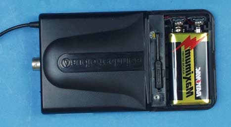
Click to zoom
Application Details
- Equipment Class
- TBC - Licensed Broadcast Station Transmitter
- Date of Grant
- May 03, 2001
- Application Purpose
- Original Equipment
- Date of Application
- May 03, 2001
- Equipment Note
- Wireless Microphone
- Frequency Range
- 470.00000000 - 480.00000000
- Company
- Audio-Technica Corporation
- Country
- Japan
Documents & Files
Document Text
Text extracted from the exhibit documents filed with the FCC. Open a document above to read the original.
Users Manual
AUDIO TECHNICA MODEL ATW-600 UHF WIRELESS MICROPHONE SYSTEM USER INFORMATION. INTRODUCTION Thank you for purchasing the ATW-600 series wireless microphone system. It is our hope that the system will bring you years of trouble free pleasure and performance. Please follow the information contained in this manual closely as it will assist you in using your equipment effectively. PART1. REGULATORY REQUIREMENTS. FCC PART 15 COMPLIANCE STATEMENT CANADA RSS-210 COMPLIANCE STATEMENT “This device complies with Part 15 of the FCC rules. Operation is subject to the condition that this device does not cause harmful interference” “This device complies with INDUSTRY CANADA R.S.S. 210, en confomite avec IC: RSS- 210/CNR210. Operation is subject to the following conditions: (1) This device may not cause harmful interference and (2) This device must accept any interference received, including interference which may cause undesired operation.” Please note that your ATW-600 system operates in a frequency band in a way, which may make its use subject to certain FCC and other regulatory agency restrictions and licensing requirements. For further information, Please contact your local office of the FCC as applicable. PART 2. USING THE ATW-T601 BELT PACK TRANSMITTER The belt pack transmitter operates on one 9V batteries. Please make sure that your batteries are fresh. We recommend that you use Alkaline batteries and that you avoid using NiCad if possible. Remove the battery cover, insert the battery into the battery compartment . Locate channels selector switch inside of the battery cover, set the channels to the corresponding channel as set on receiver. Connect your microphone or guitar cable to the connector on the topside of the transmitter. Turn the transmitter switch to the on position. Confirm that the receiver is receiving RF and the audio is passing through the receiver. You are now set to use the system. PART 3. USING THE ATW-T602 HANDHELD TRANSMITTER The handheld transmitter operates on one 9V battery. Please make sure that your batteries are fresh. We recommend that you use Alkaline batteries and that you avoid using NiCad if possible. Remove the battery cover by unscrew and pull the cover off and insert the battery into the battery compartment and screw the battery compartment back into place. To change the cannel of operation, unscrew the battery cover and pull the cover off Locate the cannel selector rotary switches. Set the channel to the corresponding channel as set on receiver. Replace cover over the rotary switches. Turn the transmitter switch to the on position. Confirm that the receiver is receiving RF. Speak directory into the microphone and confirm audio is passing through the receiver You are now set to use the system. PART4. USING THE ATW-R600 RECEIVER The ATW-R600 receiver operates with AC adapter supplied . Connect AC adapter DC output plug to receiver DC in jack and AC cable to adapter AC plug. Plug the other end of AC cable into an AC outlet. Confirm that the LED comes on. Check the cannel setting to confirm that they correspond to the settings of the transmitter Connect the unbalanced audio output to your mixer or PA system. Adjust the receiver and mixer of PA system volume setting to the desired level. Speak into the microphone and listen to the audio out at the speaker. If satisfied with the audio quality, you can use the system.
Internal Photos
Audio Board, Side 1 Audio Board, Side 2 RF Board, Side 1 w/o Shield RF Board, Side 2 w/o Shield
Internal Photos
Audio Board, Side 1 Audio Board, Side 2 RF Board, Side 1 w/o Shield RF Board, Side 2 w/o Shield
Operational Description
OPERATIONAL DESCRIPTION The ATW-T601x is a 8 milliwatt (ERP(d), UHF, frequency modulated, synthesized, transmitter configured as a portable belt-pack for wireless microphone applications under Part 74. Power supply consists of a 9 volt battery.
Parts List/Tune Up Info
Subsection 2.983(d)(9): Factory Tune-up Procedure Test Equipment 1. BNC-P Coaxial RF cable Audio Technica custom RF cable 2. DC Power Supply Kenwood PR-18 3. Audio Signal Generator Leader LAG126 4. Modulation Meter (FM liner detector) Anritsu MS61A 5. Spectrum Analyzer Advantest R3261A 6. Pre amplifier Anritsu MH648A 7. Oscilloscope Iwatsu SS-5705 8. DC Volt Meter Advantest TR6845 9. AC Millivolt Meter National VP9680A Adjustment of T601 circuit board 1. Connect the audio, switch and RF circuit board of ATW-T601. 2. Supply 9V from DC power supply to the power supply terminal (CNP 24 and 25) of T601 3. Connect BNC-P coaxial RF cable with input connector of Spectrum analyzer. 4. Connect BNC-P coaxial RF cable to JK100 terminal of T601 5. Set T601 to channel “3”. 6. Set the center frequency of Spectrum analyzer to oscillation frequency of T601, and set frequency span to 3GHz. 7. Set the power switch of T601 (SW50) to ST-BY position. Make sure to confirm that when turn the power on, power LED lights. 8. Make sure that RF signal appears on Spectrum analyzer and no parasitic oscillation observed. 9. Adjust and set the VR100 where Maximum RF output (10mW) could obtainable as well as power supply current not exceeded 65mA and spurious level could set minimum (less than 45dB). 10. Set frequency span of the Spectrum analyzer to 100KHz. 11. Set RF signal on the Spectrum analyzer to a desired Oscillating frequency by turning the VC130 onT601. 12. Gradually reduce power supply voltage from 9 V to 6.5V and make sure that Oscillating frequency stay same. 13. Check the power indicator LED start to blink l when power supply voltage reached to 6.5V. 14. Set frequency span to maximum. 15. Gradually move power supply voltage from 9 V to 6.5V and make sure that no parasitic oscillation observed. 16. Set the Power supply voltage back to 9V. 17. Remove the BNC-P coaxial RF cable from the input connector of Spectrum analyzer, and connect it to the Preamplifier. 18. Make sure that the Preamplifier and Modulation Meter (FM linear detector) are connected together. 19. Input –38.0dBV at 1kHz signal from the Audio signal generator to the Mic input of T601 by checking the level of the signal on AC milli voltmeter. 20. Set T601 trimmer (VR1) to maximum. 21. Set T601 to channel “3” and set the frequency range of the Modulation meter (FM linear detector) to the oscillation frequency of T601 22. Make sure that Oscilloscope has no irregular wave. Then, set the modulation levels appeared on the Modulation meter (FM linear detector) to +/-10KHz by turning VR2 on T601. 23. Set T601 to channel “0” and “7”. Make sure that Deviation of the each cannel stays same. 24. Switch signal input of T601 from Mic to GT. 25. Input –24.6dB at 1kHz signal from audio signal generator to GT input of T601 by checking the level of the signal on AC millivolt meter. 26. Set T601 to channel “0”,”3” and “7”. Make sure that deviation on each channel stays 15 +/- 2kHz.
Test Report
ENGINEERING STATEMENT For Type Certification of AUDIO-TECHNICA CORPORATION Model: ATW-T601x FCC ID: JFZT601x I am an Electronics Engineer, a principal in the firm of Hyak Laboratories, Inc., Springfield, Virginia. My education and experience are a matter of record with the Federal Communications Commission. Hyak Laboratories, Inc. has been retained by Audio-Technica US, Inc., to make type certification measurements on the ATW- T601x transmitter. These tests made by me or under my supervision in our Springfield laboratory. Test data required by the FCC for type certification are included in this report. It is submitted that the above mentioned transmitter meets FCC requirements and type certification is requested. ______________________________ Rowland S. Johnson Dated: March 21, 2001 A. INTRODUCTION The following data are submitted in connection with this request for type certification of the ATW-T601x transmitter in accordance with Part 2, Subpart J of the FCC Rules. The ATW-T601x is a 9 milliwatt (ERP(d), UHF, frequency modulated, synthesized, transmitter configured as a portable belt-pack for wireless microphone applications under Part 74. Power supply consists of a 9 volt battery. B. GENERAL INFORMATION REQUIRED FOR TYPE CERTIFICATION (Paragraph 2.983 of the Rules) 1. Name of applicant: Audio Technica Corporation 2. Identification of equipment: FCC ID: JFZT601x a. The equipment identification label is included as a separate exhibit. b. Photographs of the equipment are included as a separate exhibit. 3. Quantity production is planned. 4. Technical description: a. Emission 80k0F3E b. Frequency range: 470 - 480 MHz. c. Operating power of transmitter is fixed at the factory at 9 mW. d. Maximum power permitted under Part 74.861(e) (1)(ii) of the rules is 250 milliwatts, and the ATW-T601x complied with those power limitations. e. Function of each active semiconductor device: See Appendix 1. f. Complete circuit diagram is included as a separate exhibit. g. A draft instruction book is included as a separate exhibit. h. The transmitter tune-up procedure is included as a separate exhibit. 2 B. GENERAL INFORMATION REQUIRED (Continued) i. A description of circuits for stabilizing frequency is included in Appendix 2. j. A description of circuits and devices employed for suppression of spurious radiation and for limiting modulation is included in Appendix 3. k. Not applicable. 5. Data for 2.985 through 2.997 follow this section. 6. RF_Power_Output (Paragraph 2.987(a) of the Rules) The device has an integral antenna. Effective radiated power (assuming an ideal dipole) was determined, by substitution, as 9 mW. NOTE: All audio measurements were made hard-wired using the normal input connector. C. MODULATION CHARACTERISTICS 1. A curve showing frequency response of the transmitter is shown in Figure 1. Reference level was a 1 kHz audio signal at 10 kHz deviation. A Boonton 8220 modulation meter was used to measure deviation. Audio output was measured from an Audio Precision System One integrated measurement system. 2. Under Section 74.861 no modulation limiting is required. Figure 2 shows deviation as a function of input does not exceed 75 kHz. 3. Occupied_Bandwidth (Paragraphs 2.989, and 74.861(6) of the Rules) Figure 2 is a plot of the sideband envelope of the transmitter taken with a Tektronix 494P spectrum analyzer. Modulation consisted of a 15 kHz tone at an input level necessary to produce 85% of the rated 25 kHz deviation, per 2.989(e)(3). NOTE: Audio bandwidth is 15 kHz, and maximum system deviation is 25 kHz. Using 2D+2F = modulation factor. Where "D" is rated system deviation, and "F" is maximum modulation frequency, an emission designator of 80k0F3E was computed. 3 FIGURE 1 MODULATION FREQUENCY RESPONSE MODULATION FREQUENCY RESPONSE FCC ID: JFZT601x FIGURE 1 4 FIGURE 2 DEVIATION VS INPUT SIGNAL SOLID LINE: 15 kHz LONG DASH: 7.5 kHz SHORT DASH: 300 Hz DEVIATION VS INPUT SIGNAL FCC ID: JFZT601x FIGURE 2 5 FIGURE 3 OCCUPIED BANDWIDTH OCCUPIED BANDWIDTH FCC ID: JFZT601x FIGURE 3 6 C. MODULATION CHARACTERISTICS (Continued) The plots are within the limits imposed by paragraph 74.861(6). The horizontal scale (frequency is 100 kHz per division) and the vertical scale (amplitude) is a logarithmic presentation equal to 10 dB per division. D. SPURIOUS EMISSIONS AT THE ANTENNA TERMINALS (Paragraph 2.991 of the Rules) NOT APPLICABLE, INTEGRAL ANTENNA. E. DESCRIPTION OF RADIATED SPURIOUS MEASUREMENT FACILITIES A description of the Hyak Laboratories’ radiation test facility is a matter of record with the FCC. The facility meets ANSI 63.4-1992 and was accepted for radiation measurements from 25 to 1000 MHz on October 1, 1976 and is currently listed as an accepted site. F. MEASUREMENTS OF SPURIOUS RADIATION Measurements of radiated spurious emissions from the ATW- T601X were made by substitution with a Tektronix 494P spectrum analyzer using Singer DM-105A calibrated dipole antennas below 1 GHz, and Polarad CA-L, and CA-S or EMCO 3115 from 1-8.0 GHz. The transmitter was located in an open field 3 meters from the test antenna. Supply was a fresh battery. The transmitter and test antennas were arranged to maximize pickup. Both vertical and horizontal test antennae polarization were employed. Reference level for the spurious radiation was taken as the carrier level. 7 TABLE 1 TRANSMITTER RADIATED SPURIOUS 476.200 MHz, 9 Vdc, 9 mW Spurious dB Below Frequency Carrier ___MHz__ Reference 1 476.200 0 1904.796 50V Required: 43+10Log(P) 22 1 Worst-case polarization, H-Horizontal, V-Vertical. All other spurious to 4.7 GHz were 30 dB or more below FCC limit. 8 G. FREQUENCY STABILITY (Paragraph 2.995(2) and 74.861 of the Rules) Measurement of frequency stability versus temperature was made at temperatures from -30 o C to +50 o C. At each temperature, the unit was exposed to test chamber ambient a minimum of 60 minutes after indicated chamber temperature ambient had stabi- lized to within ±2° of the desired test temperatur…
Text truncated - open the document above for the full version.
Contact Information
Applicant
Fumio Kamimura(General Manager, Engineering Planning Division)
Test Firm
Hyak Laboratories, Inc.Rowland Johnson
703-451-1188
Technical Specifications
| # | Rule Parts | Frequency Range | Power Output | Emission | Tolerance |
|---|---|---|---|---|---|
| 1 | 74 | 470 MHz - 480 MHz | 9.00 mW | 80K0F3E | 0.0050000000 % |
Other Applications from Audio-Technica Corporation
JFZDT3207DF2
Apr 06, 2026DESK STAND TRANSMITTER
Equipment Class
DWM - Part 15 Wireless MicrophoneJFZT210CS
Jul 17, 2024UniPak Transmitter
Equipment Class
TLD - Licensed LPAS DeviceJFZT220CS
Jul 17, 2024Handheld Transmitter
Equipment Class
TLD - Licensed LPAS DeviceJFZCKS50TW2R
Jun 10, 2024Wireless Headphones
Equipment Class
DTS - Digital Transmission SystemJFZCKS30TWPR
Apr 02, 2024Wireless Headphones
Equipment Class
DSS - Part 15 Spread Spectrum Transmitter