JHS69229100Industrial System with Wi-Fi
BCM Advanced Research Inc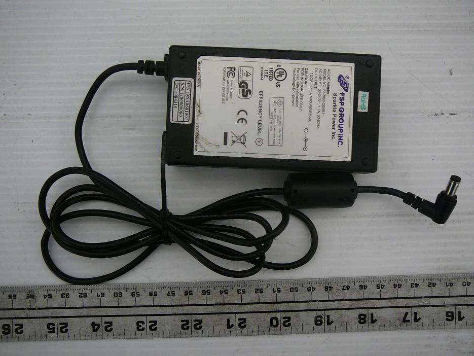
Click to zoom
Application Details
- Equipment Class
- DTS - Digital Transmission System
- Date of Grant
- Jun 03, 2010
- Application Purpose
- Original Equipment
- Date of Application
- Jun 03, 2010
- Equipment Note
- Industrial System with Wi-Fi
- Frequency Range
- 2412.00000000 - 2462.00000000
- Company
- BCM Advanced Research Inc
- Country
- United States
Documents & Files
Document Text
Text extracted from the exhibit documents filed with the FCC. Open a document above to read the original.
Users Manual
SEDASYS ® Connectivity Unit Operator’s Manual (Document Number: EES0000700) DRAFT This page is intentionally left blank. DRAFT iii COPYRIGHT INFORMATION All rights are reserved. No one is permitted to reproduce or duplicate, in any form, the whole or part of this manual, without permission from Ethicon Endo-Surgery, Inc. PRODUCT INFORMATION MANUFACTURED BY: ETHICON ENDO-SURGERY, INC. 4545 Creek Road Cincinnati,Ohio 45242-2839 USA OWNERSHIP The SCU is the property of Ethicon Endo-Surgery, Inc., and is placed in the facility in accordance with the contractual arrangement between Ethicon Endo-Surgery and the facility. COMPLIANCE AND CERTIFICATE CE Declaration: CE marking is a visible declaration by the manufacturer or his authorized representatives that the electrical equipment to which it relates satisfies all the provisions of the 1994 Regulations. FCC Compliance: This device complies with Part 15 of the FCC Rules. Operation of the device is subject to the following two conditions: •This device may not cause harmful interference. •This device must accept any interference that may cause undesired operation. This equipment generates uses and can radiate radio frequency energy and, if not installed and used in accordance with the instructions, may cause interference to radio communications. This equipment has been tested and found to comply with the limits for a Class B digital device, pursuant to Part 15 of the FCC Rules. These limits are designed to Product CodeProduct SEDSCU01SEDASYS Connectivity Unit (SCU) External Standard Conformance TBD DRAFT iv provide reasonable protection against harmful interference. However, there is no guarantee that interference will not occur in a particular installation. If this equipment does cause harmful interference to radio or television reception, which can be determined by turning the equipment off and on, the user is encouraged to try to correct the interference by one or more of the following measures: •Reorient or relocate the antenna of the radio/television receiver. •Increase the separation between this equipment and the radio/ television receiver. •Plug the equipment into a different outlet so that the equipment and the radio/television receiver are on different power mains branch circuits. •Consult a representative of EES or an experienced radio/television technician for additional suggestions. Note Changes or modification not expressly approved by EES for compliance could void the user’s authority to operate the equipment. DRAFT v SERVICE AND SUPPORT INFORMATION Within the USA contact: EES Customer Support Center, 1-800-SEDASYS, 1-800-733-2797 (English speaking only) Outside of USA contact: Local Johnson & Johnson Affiliate office or closest Authorized Service Center Authorized Service Centers locations: USA Ethicon Endo-Surgery, Inc. 4480 Lake Forest Drive Suite 318 Cincinnati, OH 45242 1-800-SEDASYS (U.S.), 1-800-733-2797 Phone: 1-513-337-8901 (International calls - English speaking only) Email: [email protected] WARNING CMOS Battery Damage Replace system’s CMOS RAM battery only with the identical CR-2032 3V Lithium-ion coin cell (or equivalent) battery type to avoid risk of personal injury or physical damage to the equipment. Improper installation might cause battery to explode. Always dispose of used batteries according to the manufacturer’s instructions, or as required by the local ordinance (where applicable). Perchlorate Material – Special Handling May Apply. See http://www.dtsc.ca.gov/hazardouswaste/perchlorate/ DRAFT vi This page is intentionally left blank. DRAFT vii DOCUMENT CONVENTIONS The following conventions are used throughout this manual: Intended Use: Refers to the objective intent of the persons legally responsible for the labeling of the device. WARNING Describes serious adverse reactions and potential safety hazards, limitations in use imposed by them, and steps that should be taken if they occur. Warnings alert the clinician to the possibility of serious injury, death, or other serious adverse reactions associated with the use or misuse of the system. Precaution Pertains to information regarding any special care to be exercised by the practitioner and/or patient for the safe and effective use of the device. Precautions alert the clinician to the possibility of minor or moderate injury to the clinician or patient, or damage to the device associated with the use or misuse of the system. Note Notes emphasize important details. DRAFT viii SYMBOLS The following symbols will be physically located on one or more components of the system. SymbolDescription NOT COMPLETE – TBD NOT COMPLETE – TBD DRAFT ix Contents Chapter 1: Introduction ............................................................................................. 1 - 1 SCU Overview .................................................................................... 1 - 1 Chapter 2: Intended Use, Warnings and Precautions ............................................ 2 - 1 Warnings ............................................................................................ 2 - 2 Precautions ........................................................................................ 2 - 3 Notes .................................................................................................. 2 - 4 Appendix A: Technical Information ........................................................................A - 1 DRAFT Contents x This page is intentionally left blank. DRAFT 1 - 1 Chapter 1 Introduction SCU Overview The SEDASYS ® Connectivity Unit (SCU) is a communications interface device for use with the SEDASYS ® System. The SCU automatically collects data from the SEDASYS ® System that is required for usage billing, and transmits that information via the facility’s IT network to Ethicon Endo-Surgery for processing and preparing an invoice for the facility. The SEDASYS ® System transmits the data, in an encrypted form, to the SCU. This communication is wireless and …
Text truncated - open the document above for the full version.
Cover Letter(s)
FCC Confidential Authorization 5/27/2010 FEDERAL COMMUNICATIONS COMMISSIONS Authorization and Evaluation Division 7435 Oakland Mills Road Columbia, MD 21046 Subject: Confidentiality Request regarding application for certification of FCC ID: JHS69229100 In accordance with Sections 0.457 and 0.459 of the Commission’s Rules, BCM Advanced Research hereby requests long-term confidential treatment of information accompanying this application as outlined below: Block Diagram Schematics The above materials contain proprietary and confidential information not customarily released to the public. The public disclosure of these materials provides unjustified benefits to its competitors in the market. Sincerely, David Ho Project Engineer Tel: (949) 470-1888 x 264 7 Marconi Irvine, CA 92618
External Photos
BCM Advanced Research FCC IC: JHS69229100, IC: 8911A-69229100 Report Number: R1004274-247 Page 47 of 52 FCC Part 15C/IC RSS-210 Test Report 16 Exhibit C - EUT Photographs 16.1 EUT – Top View 16.2 EUT-Side View BCM Advanced Research FCC IC: JHS69229100, IC: 8911A-69229100 Report Number: R1004274-247 Page 48 of 52 FCC Part 15C/IC RSS-210 Test Report 16.3 EUT-Rear Side View 16.4 Power Supply View
Internal Photos
BCM Advanced Research FCC IC: JHS69229100, IC: 8911A-69229100 Report Number: R1004274-247 Page 49 of 52 FCC Part 15C/IC RSS-210 Test Report 16.5 EUT- Cover off View 16.6 Main Board Top View BCM Advanced Research FCC IC: JHS69229100, IC: 8911A-69229100 Report Number: R1004274-247 Page 50 of 52 FCC Part 15C/IC RSS-210 Test Report 16.7 Main Board Solder View 16.8 Wi-Fi Card- Front View BCM Advanced Research FCC IC: JHS69229100, IC: 8911A-69229100 Report Number: R1004274-247 Page 51 of 52 FCC Part 15C/IC RSS-210 Test Report 16.9 Wi-Fi Card- Back View 16.10 Hard Drive View BCM Advanced Research FCC IC: JHS69229100, IC: 8911A-69229100 Report Number: R1004274-247 Page 52 of 52 FCC Part 15C/IC RSS-210 Test Report 16.11 Memory View 16.12 Antenna View ***** END OF REPORT *****
RF Exposure Info
BCM Advanced Research FCC IC: JHS69229100, IC: 8911A-69229100 Report Number: R1004274-247 Page 10 of 52 FCC Part 15C/IC RSS-210 Test Report 4 FCC §15.247 (i), §2.1091 & IC RSS-102 - RF Exposure 4.1 Applicable Standard According to FCC §15.247(i) and §1.1307(b)(1), systems operating under the provisions of this section shall be operated in a manner that ensures that the public is not exposed to radio frequency energy level in excess of the Commission’s guidelines. Limits for General Population/Uncontrolled Exposure Frequency Range (MHz) Electric Field Strength (V/m) Magnetic Field Strength (A/m) Power Density (mW/cm 2 ) Averaging Time (minutes) Limits for General Population/Uncontrolled Exposure 0.3-1.34 614 1.63 * (100) 30 1.34-30 824/f 2.19/f * (180/f 2 ) 30 30-300 27.5 0.073 0.2 30 300-1500 / / f/1500 30 1500-100,000 / / 1.0 30 f = frequency in MHz * = Plane-wave equivalent power density Before equipment certification is granted, the procedure of IC RSS-102 must be followed concerning the exposure of humans to RF fields. According to IC RSS-102 Issue 2 section 4.1, RF limits used for general public will be applied to the EUT. Frequency Range (MHz) Electric Field (V/m rms) Magnetic Field (A/m rms) Power Density (W/m 2 ) Time Averaging (min) 0.003 - 1 280 2.19 - 6 1 - 10 280 / f 2.19 / f - 6 10 - 30 28 2.19 / f - 6 30 – 300 28 0.073 2* 6 300 – 1 500 1.585 f 0.5 0.0042 f 0.5 f / 150 6 1 500 – 15 000 61.4 0.163 10 6 15 000 – 150 000 61.4 0.163 10 616000 / f 1.2 150 000- 300 000 0.158 f 0.5 4.21 x 10 -4 f 0.5 6.67 x 10 -5 f 616000 / f 1.2 Note: ƒ is frequency in MHz * = Power density limit is applicable at frequencies greater than 100 MHz BCM Advanced Research FCC IC: JHS69229100, IC: 8911A-69229100 Report Number: R1004274-247 Page 11 of 52 FCC Part 15C/IC RSS-210 Test Report 4.2 MPE Prediction Predication of MPE limit at a given distance, Equation from OET Bulletin 65, Edition 97-01 S = PG/4πR² Where: S = power density P = power input to antenna G = power gain of the antenna in the direction of interest relative to an isotropic radiator R = distance to the center of radiation of the antenna 4.3 MPE Results Maximum peak output power at antenna input terminal (dBm): 19.60 Maximum peak output power at antenna input terminal (mW): 91.20 Prediction distance (cm): 20 Prediction frequency (MHz): 2412 Maximum Antenna Gain, typical (dBi): 2.0 Maximum Antenna Gain (numeric): 1.58 Power density of prediction frequency at 20.0 cm (mW/cm 2 ): 0.0287 Power density of prediction frequency at 20.0 cm (W/m 2 ): 0.287 MPE limit for uncontrolled exposure at prediction frequency (mW/cm 2 ): 1.0 MPE limit for uncontrolled exposure at prediction frequency (W/m 2 ): 10 The device is compliant with the requirement MPE limit for uncontrolled exposure. The maximum power density at the distance of 20 cm is 0.0287mW/cm 2 (0.287W/m 2 ).Limit is 1mW/cm 2 (10W/m 2 ).
Test Report
Note: This test report is prepared for the customer shown above and for the device described herein. It may not be duplicated or used in part without prior written consent from Bay Area Compliance Laboratories Corp. This report must not be used by the customer to claim product certification, approval, or endorsement by NVLAP*, NIST, or any agency of the Federal Government. * This report may contain data that are not covered by the NVLAP accreditation and are marked with an asterisk “*” (Rev.2) FCC PART 15 SUBPART C IC RSS-210, ISSUE 7, JUNE 2007 TEST AND MEASUREMENT REPORT For BCM Advanced Research 7 Marconi, Irvine, CA 92618, USA Report Type: Original Report Product Type: Industrial System with Wi-Fi Test Engineers: Kevin Li Report Number: R1004274-247 Report Date: 2010-05-21 Reviewed By: Victor Zhang Testing Engineer Prepared By: (84) Bay Area Compliance Laboratories Corp. 1274 Anvilwood Avenue, Sunnyvale, CA 94089, USA Tel: (408) 732-9162 Fax: (408) 732-9164 FCC ID: JHS69229100 IC: 8911A-69229100 BCM Advanced Research FCC IC: JHS69229100, IC: 8911A-69229100 Report Number: R1004274-247 Page 2 of 52 FCC Part 15C/IC RSS-210 Test Report TABLE OF CONTENTS 1 General Description .................................................................................................................................................... 5 1.1 Product Description for Equipment Under Test (EUT) ......................................................................................... 5 1.2 Mechanical Description of EUT ............................................................................................................................ 5 1.3 EUT Photo ............................................................................................................................................................. 5 1.4 Objective ................................................................................................................................................................ 5 1.5 Related Submittal(s)/Grant(s) ................................................................................................................................ 6 1.6 Test Methodology .................................................................................................................................................. 6 1.7 Measurement Uncertainty ...................................................................................................................................... 6 1.8 Test Facility ........................................................................................................................................................... 6 2 System Test Configuration ......................................................................................................................................... 7 2.1 Justification ............................................................................................................................................................ 7 2.2 EUT Exercise Software.......................................................................................................................................... 7 2.3 Equipment Modifications....................................................................................................................................... 7 2.4 Special Accessories................................................................................................................................................ 7 2.5 Local Support Equipment ...................................................................................................................................... 7 2.6 Power Supply and Line Filters ............................................................................................................................... 7 2.7 Interface Ports and Cabling .................................................................................................................................... 8 2.8 EUT Configuration Details .................................................................................................................................... 8 3 Summary of Test Results ............................................................................................................................................ 9 4 FCC §15.247 (i), §2.1091 & IC RSS-102 - RF Exposure .......................................................................................... 10 4.1 Applicable Standard ............................................................................................................................................. 10 4.2 MPE Prediction .................................................................................................................................................... 11 4.3 MPE Results......................................................................................................................................................... 11 5 FCC §15.203 & IC RSS-Gen §7.1.4 – Antenna Requirements ................................................................................ 12 5.1 Applicable Standard ............................................................................................................................................. 12 5.2 Antenna Connector Construction ......................................................................................................................... 12 6 FCC §15.207 & IC RSS-Gen 7.2.2- Conducted Emissions....................................................................................... 13 6.1 Applicable Standards ........................................................................................................................................... 13 6.2 Test Setup............................................................................................................................................................. 13 6.3 Test Equipment List and…
Text truncated - open the document above for the full version.
Test Setup Photos
BCM Advanced Research FCC IC: JHS69229100, IC: 8911A-69229100 Report Number: R1004274-247 Page 44 of 52 FCC Part 15C/IC RSS-210 Test Report 15 Exhibit B - Test Setup Photographs 15.1 Radiated Emission below 1GHz Front View @ 3 Meter 15.2 Radiated Emission below 1GHz Rear View @ 3 Meter BCM Advanced Research FCC IC: JHS69229100, IC: 8911A-69229100 Report Number: R1004274-247 Page 45 of 52 FCC Part 15C/IC RSS-210 Test Report 15.3 Radiated Emission above 1 GHz Front View @ 3 Meter 15.4 Radiated Emission above 1 GHz Rear View @ 3 Meter BCM Advanced Research FCC IC: JHS69229100, IC: 8911A-69229100 Report Number: R1004274-247 Page 46 of 52 FCC Part 15C/IC RSS-210 Test Report 15.5 AC Line Conducted Emission Front View 15.6 AC Line Conducted Emission Side View
Contact Information
Applicant
Jack Phone(Manager)
714 470-1888Fax: 714 470-0883
Test Firm
Bay Area Compliance LaboratoryJohn Chan
Technical Specifications
| # | Rule Parts | Frequency Range | Power Output |
|---|---|---|---|
| 2 | 15C | 2.41 GHz - 2.46 GHz | 51.00 mW |
Other Applications from BCM Advanced Research Inc
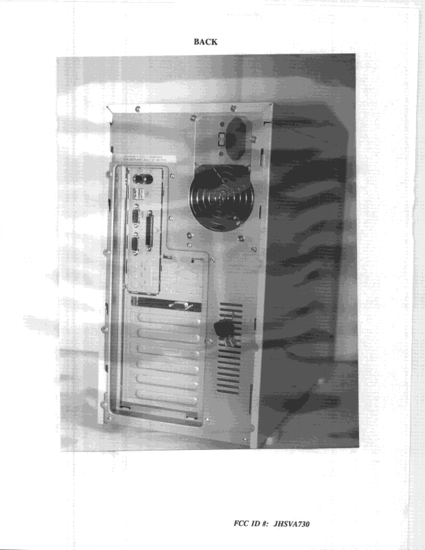
JHSVA730
Jan 28, 1999JBC - Part 15 Class B Computing Device/Personal Computer
Equipment Class
JBC - Part 15 Class B Computing Device/Personal Computer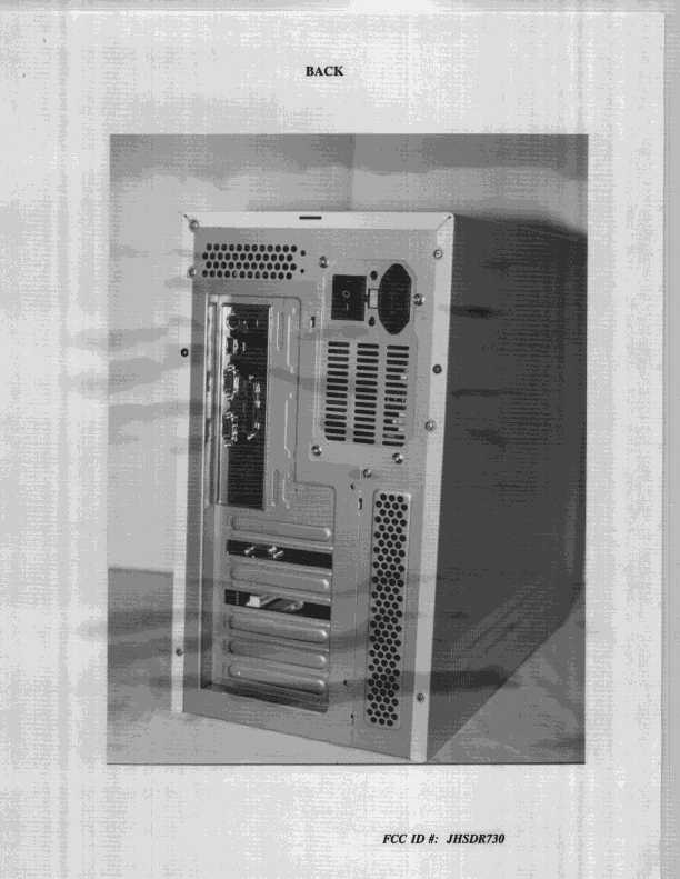
JHSDR730
Jul 23, 1998JBC - Part 15 Class B Computing Device/Personal Computer
Equipment Class
JBC - Part 15 Class B Computing Device/Personal Computer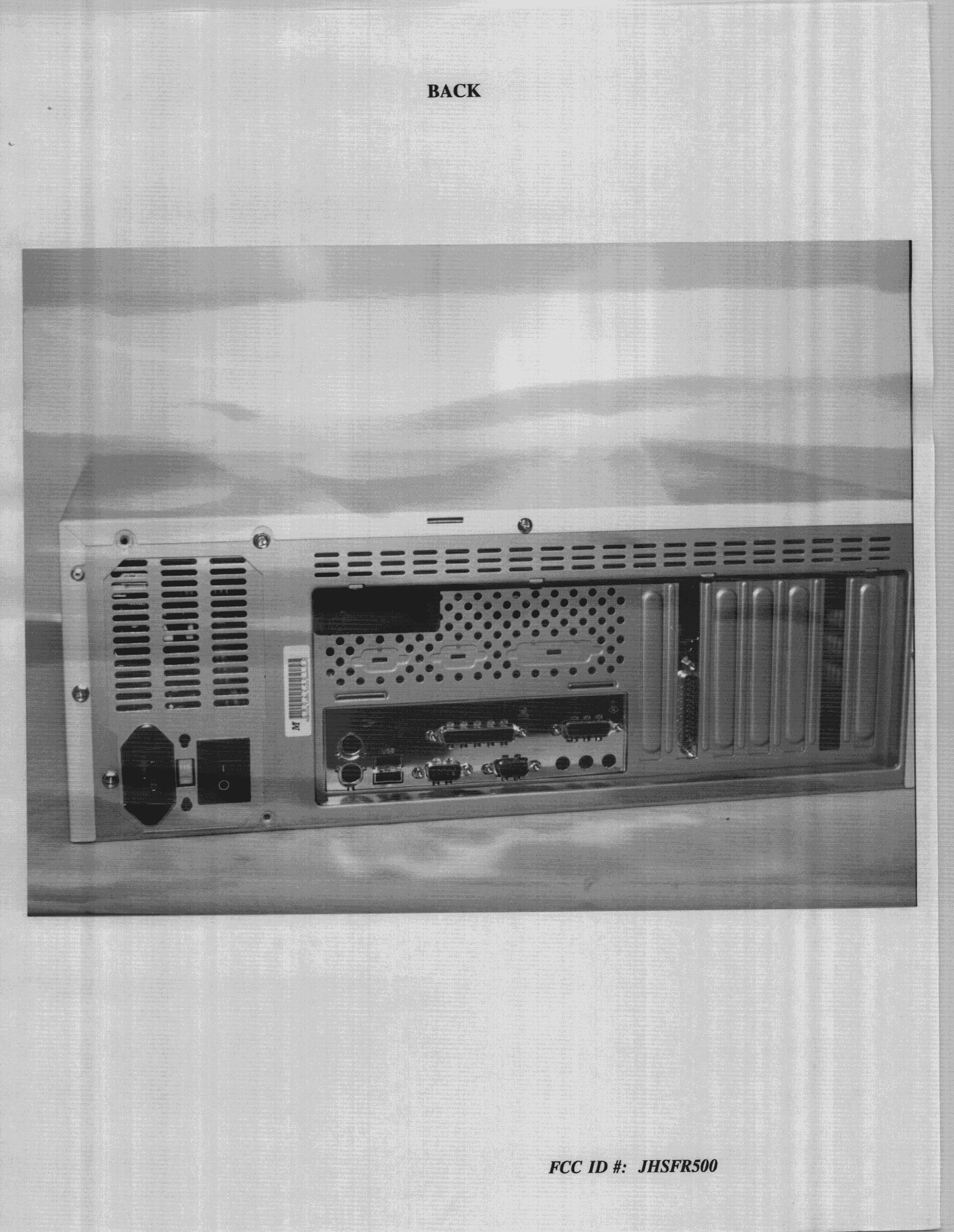
JHSFR500
Jun 28, 1998JBC - Part 15 Class B Computing Device/Personal Computer
Equipment Class
JBC - Part 15 Class B Computing Device/Personal ComputerJHSKR632
Mar 08, 1998JBC - Part 15 Class B Computing Device/Personal Computer
Equipment Class
JBC - Part 15 Class B Computing Device/Personal ComputerJHSKR630
Mar 02, 1998JBC - Part 15 Class B Computing Device/Personal Computer
Equipment Class
JBC - Part 15 Class B Computing Device/Personal Computer