JI9-F21-2S-030Industrial Radio Remote Controller
Intercontinental Technologies Ltd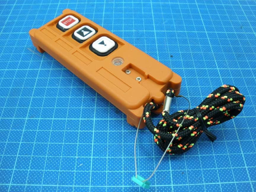
Click to zoom
Application Details
- Equipment Class
- DSC - Part 15 Security/Remote Control Transmitter
- Date of Grant
- Jul 25, 2012
- Application Purpose
- Original Equipment
- Date of Application
- Jul 25, 2012
- Equipment Note
- Industrial Radio Remote Controller
- Frequency Range
- 317.79000000 - 317.79000000
- Country
- United States
Documents & Files
Document Text
Text extracted from the exhibit documents filed with the FCC. Open a document above to read the original.
Users Manual
Intercontinental Technologies Ltd. 558 Plate Drive Bldg. #2, East Dundee, IL 60118 Ph: 847-426-9597, Fax: 847-426-9724, TELECRANE.COM Telecrane Radio Remote Control F21 Series & F24 Series Manual Rev. 4a April 18, 2012 1 Telecrane F21 Series & F24 Series Manual Chapter Index Page General Specifications 3 1.0 Installation Instructions 5 2.0 Operation Instructions 6 3.0 Safety 8 4.0 Troubleshooting on Installation 10 5.0 Programming 11 6.0 Internal Horn Option 13 7.0 Product Selection Guide 14 8.0 Product Options 16 9.0 F21 Receiver and Wiring Diagrams 17 10.0 F24 Receiver and Wiring Diagrams 18 Program and Button Labeling 19 This manual Copyright 2006, 2009, 2011 Intercontinental Technologies, Ltd. 2 This Page Intentionally Left Blank 3 Technical Specifications for: F21-2S, 2D, 4S, 4D, 6S and F24-6S, 6D, 8S, 8D, 10S, 10D, 12S, 12D Receiver input voltage: 110 volts AC. Other Input voltages available 220 VAC, 12V AC/DC, 24 VAC/DC Temperature: -35 deg C to 75 deg C (-31 deg F to 167 deg F) Receiver relay ratings: the receiver relays are rated at 10 amps at 250 volts AC. All COM wires are fused at 10A in both the F21 and F24 series. The total current drawn through the receiver relays (through the COM wire) must not exceed 10A. Transmitter weights: 5 ounces for F21-2S, 2D; 9 ounces for F21-4S, 4D, 6S; 11 ounces for F24-6S, 6D, 8S, 8D, 10S, 10D Transmitter dimensions: F21-2S, 2D are 5.2” x 1.75” x .9”; F21-4S, 4D, 6S are 6.2” x 2.4”x2”; F24-6S, 6D, 8S, 8D, 10S, 10D, 12S, 12D are 7.25” x 2.4” x 2” Frequency generation: Crystal (plug-in) Transmitter and Receiver housing material: 30% glass fiber-reinforced nylon-6 Transmitter button life: Tested to 2,000,000 operations Control range: 150 feet for F21-2 button models, 250 feet for F21-4 & F21-6 button models and 500+ feet for all F24 models. Transmitter batteries: 2 AA alkaline batteries. Channel Frequency Channel Frequency Channel Frequency Channel Frequency 1 310.0325 11 312.7075 21 315.3825 31 318.0575 2 310.3000 12 312.9750 22 315.6500 32 318.3250 3 310.5675 13 313.2425 23 315.9175 33 318.5925 4 310.8350 14 313.5100 24 316.1850 34 318.8600 5 311.1025 15 313.7775 25 316.4525 35 319.1275 6 311.3700 16 314.0450 26 316.7200 36 319.3950 7 311.6375 17 314.3125 27 316.9875 37 319.6625 8 311.9050 18 314.5800 28 317.2550 38 319.9300 9 312.1725 19 314.8475 29 317.5225 10 312.4400 20 315.1150 30 317.7900 Channel Frequency Channel Frequency Channel Frequency Channel Frequency 112 428.5350 123 431.4775 134 434.4200 145 437.3625 113 428.8025 124 431.7450 135 434.6875 146 437.6300 114 429.0700 125 432.0125 136 434.9550 147 437.8975 115 429.3375 126 432.2800 137 435.2225 148 438.1650 116 429.6050 127 432.5475 138 435.4900 149 438.4325 117 429.8725 128 432.8150 139 435.7575 118 430.1400 129 433.0825 140 436.0250 119 430.4075 130 433.3500 141 436.2925 120 430.6750 131 433.6175 142 436.5600 121 430.9425 132 433.8850 143 436.8275 122 431.2100 133 434.1525 144 437.0950 4 Warranty: Intercontinental Technologies, Ltd. (ITL) guarantees that this product meets its published specifications at the time of shipment. This equipment is warranted against defects in material and manufacturing for a period of one year from the date of shipment. During the warranty period, ITL will repair or replace defective components at no charge, if the failure of the product was due to defective material or manufacturing. For warranty service, the product must ultimately be returned to ITL. The buyer must pay shipping charges to the ITL service facility, and ITL will pay return ground shipping charges. Warranty service on F21 and F24 units shall be provided by ITL only and ITL will not be responsible for service or repair costs charged by third parties. ITL will not be liable for any damage to the warranted product, and no other warranty is expressed or implied, except as explicitly described. ITL does not warranty any consumable parts, including batteries, fuses, buttons, relays, or housings. This warranty does not include damage caused by improper installation (including ignoring environmental specifications), improper or insufficient maintenance, any modifications, improper operation, or improper software interfacing. The remedies provided herein are the buyer’s sole and exclusive remedies. ITL shall not be liable for any direct, indirect, special, incidental, or consequential damages. FCC and Industry Canada Approval Information The following information applies to transmitters: This device complies with part 15 of the FCC Rules and RSS-210 of Industry Canada. Operation is subject to the following two conditions: (1) This device may not cause harmful interference, and (2) this device must accept any interference received, including interference that may cause undesired operation. Changes or modifications not expressly approved by Intercontinental Technologies, Ltd. could void the user’s authority to operate equipment. Ce dispositif est conforme aux normes CNR-210 d’Industrie Canada et la partie 15 des règles de la FCC. L’utilisation de ce dispositif est autorisée seulement aux conditions suivantes: 1) il ne doit pas produire de brouillage et 2) l’utilisateur du dispositif doit être prêt à accepter tout brouillage radioelectrique reçu, même si ce brouillage est susceptible de compromettre le fonctionnement du dispositif . This equipment has been tested and found to comply with the limits for a Class A digital device, pursuant to Part 15 of the FCC Rules. These limits are designed to provide reasonable protection against harmful interference when the equipment is operated in a commercial environment. This equipment generates, uses, and can radiate radio frequency energy and, if not installed and used in accordance with the instruction manual, may cause harmful interference to radio communications. Operation of this equipment in a residential area is likely to cause harmful interference in which case the user will be required to correct the interference at his own expense. The following…
Text truncated - open the document above for the full version.
External Photos
External photo of EUT
ID Label/Location Info
Label FCC ID Label Location
Test Report
FCC ID.: JI9-F21-2S-030 Report No.: TS12060207-EME Page 1 of 15 0597 EMC TEST REPORT Report No. : TS12060207-EME Model No. : F21-2S-TX Issued Date : Jul. 13, 2012 Applicant: Intercontinental Technologies, Ltd. 558-2 Plate Drive, East Dundee IL 60118 USA Test Method/ Standard: 47 CFR FCC Part 15.231 & ANSI C63.4 2003 Test By: Intertek Testing Services Taiwan Ltd. No. 11, Lane 275, Ko-Nan 1 Street, Chia-Tung Li, Shiang-Shan District, Hsinchu City, Taiwan It may be duplicated completely for legal use with the allowance of the applicant. It shall not be reproduced except in full, without the written approval of Intertek Laboratory. The test result(s) in this report only applies to the tested sample(s). The test report was prepared by: Sign on File Sunny Liu/ Senior Officer These measurements were taken by: Sign on File Terry Hsu / Engineer The test report was reviewed by: Name Jimmy Yang Title Engineer FCC ID.: JI9-F21-2S-030 Report No.: TS12060207-EME Page 2 of 15 Table of Contents Summary of Tests ....................................................................................................................... 3 1. General information ............................................................................................................... 4 1.1 Identification of the EUT ................................................................................................. 4 1.2 Additional information about the EUT............................................................................. 4 1.3 Antenna description.......................................................................................................... 5 2. Test specifications .................................................................................................................. 6 2.1 Test standard..................................................................................................................... 6 2.2 Operation mode ................................................................................................................ 6 2.3 Test equipment ................................................................................................................. 6 3. Radiated emission test FCC 15.231 (b).................................................................................. 7 3.1 Operating environment..................................................................................................... 7 3.2 Test setup & procedure.....................................................................................................7 3.3 Radiated emission limit ....................................................................................................9 3.3.1 Fundamental and harmonics emission limits ................................................................ 9 3.3.2 General radiated emission limit..................................................................................... 9 3.4 Radiated emission test data FCC 15.231........................................................................ 10 3.4.1 Measurement results: Fundamental emission ............................................................. 10 3.4.2 Measurement results: frequencies equal to or less than 1 GHz................................... 11 3.4.3 Measurement results: frequency above 1GHz ............................................................ 12 4. Measured bandwidth FCC 15.231(C) .................................................................................. 13 5. Timing requirement of manually operated transmitter......................................................... 14 6. Conducted emission FCC 15.207......................................................................................... 15 FCC ID.: JI9-F21-2S-030 Report No.: TS12060207-EME Page 3 of 15 Summary of Tests Test Item Reference Results Radiated Emission test 15.231(b), 15.209 Pass Measured bandwidth 15.231(c) Pass Timing requirement of manually operated transmitter 15.231(a)(1) Pass Conducted Emission test 15.231(b), 15.207 N/A FCC ID.: JI9-F21-2S-030 Report No.: TS12060207-EME Page 4 of 15 1. General information 1.1 Identification of the EUT Product: Industrial Radio Remote Controller Model No.: F21-2S-TX FCC ID.: JI9-F21-2S-030 Frequency Range: 317.7900 MHz Channel Number: Single channel Frequency of Each Channel: 317.7900 MHz Access scheme: AFSK Power Supply: DC 3 V from battery Power Cord: N/A Sample Received: Jun. 22, 2012 Test Date(s): Jun. 26, 2012 ~ Jul. 11, 2012 Note 1: This report is for the exclusive use of Intertek's Client and is provided pursuant to the agreement between Intertek and its Client. Intertek's responsibility and liability are limited to the terms and conditions of the agreement. Intertek assumes no liability to any party, other than to the Client in accordance with the agreement, for any loss, expense or damage occasioned by the use of this report. Only the Client is authorized to permit copying or distribution of this report and then only in its entirety. Any use of the Intertek name or one of its marks for the sale or advertisement of the tested material, product or service must first be approved in writing by Intertek. The observations and test results in this report are relevant only to the sample tested. This report by itself does not imply that the material, product, or service is or has ever been under an Intertek certification program. Note 2: When determining the test conclusion, the Measurement Uncertainty of test has been considered. 1.2 Additional information about the EUT The EUT is Industrial Radio Remote Controller, and was defined as information technology equipment. For more detail features, please refer to User's manual as file name “Installation guide.pdf” FCC ID.: JI9-F21-2S-030 Report No.: TS12060207-EME Page 5 of 15 1.3 Antenna description The antenna is affixed to the EUT using a unique connector, which allows for replacement of a broken antenna, but DOES NOT use a standard a…
Text truncated - open the document above for the full version.
Test Setup Photos
Radiated Set-up photo of EUT Below 1GHz Below 1GHz Radiated Set-up photo of EUT Above 1GHz Above 1GHz
Contact Information
Applicant
Steve Habisohn(President)
Technical Contact
Intertek Testing Services Taiwan Ltd.Sunny Liu
[email protected]886-3-5191411
No. 11, Lane 275, Ko-Nan 1 Street, Chia-Tung Li, · Hsinchu City · Taiwan
Non-Technical Contact
Intertek Testing Services Taiwan Ltd.Sunny Liu
[email protected]886-3-5191411
Test Firm
Intertek Testing Services Taiwan Ltd.Lily Shih
Technical Specifications
| # | Rule Parts | Frequency Range | Power Output |
|---|---|---|---|
| 1 | 15.231 | 317.79 MHz - 317.79 MHz | - |
Other Applications from Intercontinental Technologies Ltd

JI9-F21-2S-038
Jul 30, 2012Industrial Radio Remote Controller
Equipment Class
DSC - Part 15 Security/Remote Control Transmitter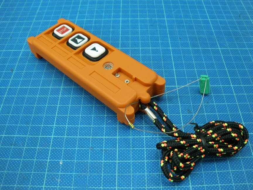
JI9-F21-2S-035
Jul 30, 2012Industrial Radio Remote Controller
Equipment Class
DSC - Part 15 Security/Remote Control Transmitter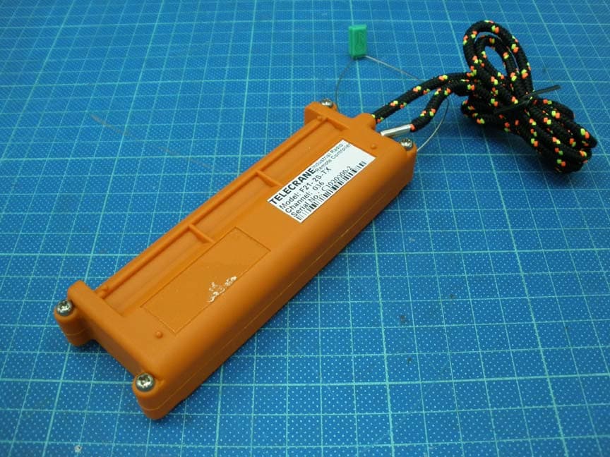
JI9-F21-2S-036
Jul 30, 2012Industrial Radio Remote Controller
Equipment Class
DSC - Part 15 Security/Remote Control Transmitter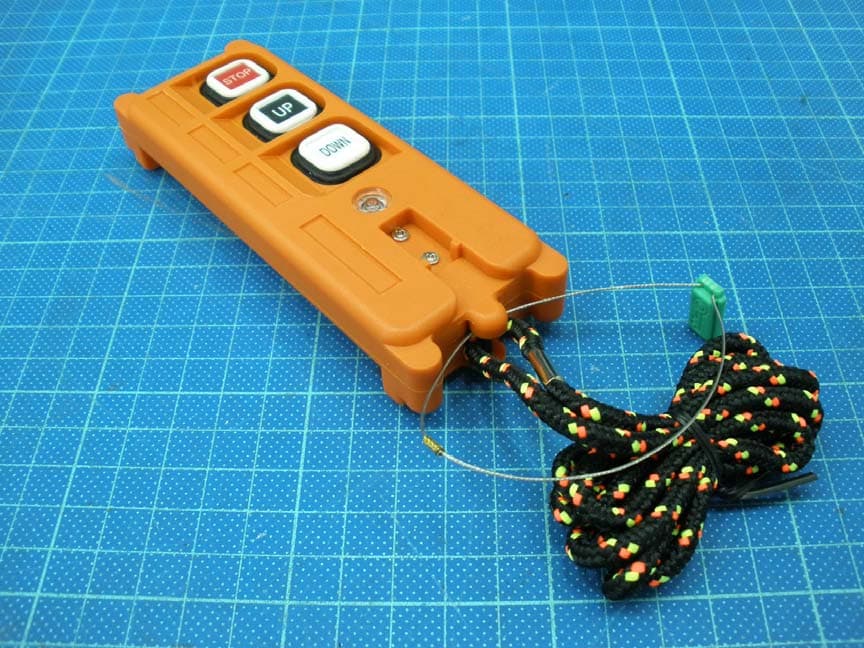
JI9-F21-2S-034
Jul 30, 2012Industrial Radio Remote Controller
Equipment Class
DSC - Part 15 Security/Remote Control Transmitter
JI9-F21-2S-037
Jul 30, 2012Industrial Radio Remote Controller
Equipment Class
DSC - Part 15 Security/Remote Control Transmitter