JIL2888Data Transport Radio
Alligator Communications Inc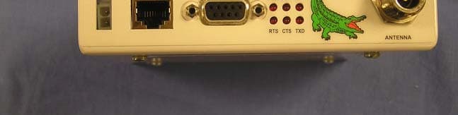
Click to zoom
Application Details
- Equipment Class
- TNB - Licensed Non-Broadcast Station Transmitter
- Date of Grant
- Mar 20, 2006
- Application Purpose
- Original Equipment
- Date of Application
- Mar 20, 2006
- Equipment Note
- Data Transport Radio
- Frequency Range
- 928.00000000 - 929.00000000
- Company
- Alligator Communications Inc
- Country
- United States
Documents & Files
Document Text
Text extracted from the exhibit documents filed with the FCC. Open a document above to read the original.
Users Manual
I Alligator Model 2888 895 - 960 MHz 1200 Baud Data Transport Radio MANUAL Version 1.10 Alligator Communications, Inc. 317 Brokaw Road Santa Clara, CA 95050 Telephone: (408) 327-0800 Fax: (408) 327-0808 Copyright 2005 Alligator Communications All Rights Reserved II CHARTER 1: GENERAL INFORMATION 1.1 General Description 1 1.2 Applications 1 1.3 Technical Specifications 1 1.4 Warranty 3 1.5 Claim for Damage in Shipment 4 1.6 Information to User As Required by FCC Section 15.21 4 1.7 RF Exposure Information 4 CHARTER 2: Radio Configuration and Operational Checkout 2.1 General Discussion 5 2.2 Operational Bench Test 5 2.2.1 Antenna Connector 5 2.2.2 Power Connector 6 2.2.3 Initial Checkout 6 2.2.3A Power Checkout 7 Figure 2.1 LED Display 7 2.2.3B LED Checkout 7 Table 2.2 LED Description Table 7 2.2.3C Transmitter Test 8 2.2.3D Receiver Test 8 2.2.3E Deviation Test 9 2.2.5 Squelch Adjustment 10 2.2.7 Deviation Adjustment 12 2.2.10 Field Simulation Test 13 Figure 2.3 DB-9 Description and Pin Locator 15 Table 2.4 DB-9 Pin Function 15 Figure 2.4 2888 Internal Circuit Board 16 Figure 2.6 Diagnostic Computer Interface Port 17 Table 2.6 Diagnostic Computer Interface Port Pin Functions 17 2.6 Diagnostic Personal Computer Interface 18 2.6.1 Model 2888 Remote Radio Local Connect 18 2.6.2 Model 1800A Master Station Link Connect 19 2.6.3 Model 1800A Master Station Phone Dial-up Connect 20 Table of Contents III CHAPTER 3: INSTALLATION 3.1 Mechanical Installation 21 3.2 Location 21 3.3 Electrical Interconnection 22 CHAPTER 4: THEORY OF OPERATION 4.1 General Discussion 23 4.2 Microprocessor Operation 23 4.3 Functions of the 2888 Radio 23 4.3.1 Diagnostic Parameters 23 4.3.2 Alarm Limits and Conditions 24 4.3.3 Operating Parameters 24 4.3.4 Communication Parameters 26 CHAPTER 5: MAINTENANCE 5.1 General Discussion 28 5.2 Test Equipment 28 CHARPTER 6: ALLIGATOR DIAGNOSTIC SOFTWARE 6.1 General Description 29 6.2 Theory of Operation 31 1 1.1 GENERAL DESCRIPTION The Alligator Communications Model 2888 is a microprocessor-controlled data radio transceiver designed to operate in accordance with FCC rules, Part 101, and in Canada under RSS-116 Issue 6. The 2888 data radio is frequency synthesized and programmable to individual transmitter and receiver frequencies in the 928-929 MHz frequency band (US), and in the 896-929 MHz frequency band (Canada). The transceiver is a fixed channel, half-duplex radio available with channel bandwidths of 12.5 kHz and 25.0 kHz. 1.2 APPLICATIONS The 2888 data radio is designed for point-to-multipoint or point-to-point licensed operations in the 900 MHz band. Some of the most common applications are: Electric Utility Substation SCADA Pipeline Flow Monitors Energy Distribution & Metering Applications Gas or Petroleum Production Well Head Control and Monitoring Water Distribution and Waste Water Collection Control and Monitoring Petroleum Production, Transmission, Storage and Distribution 1.3 TECHNICAL SPECIFICATIONS GENERAL Frequency Agility: 895.00 – 960.00 MHz, 6.25 kHz per Step Channel Spacing: Available in 12.5, 25.0 KHz Bandwidths Data Rates: 1200 bps Input Voltage: 13.2 Vdc Nominal (11-16 Vdc) Current Consumption: * Receive Mode: 100 mA * Transmit Mode (5.00 Watts): < 1.75 A Connectors: * Antenna: Type “N” Female * Data: DB-9F, Subminiature 1.0 General Information 2 * Power: 2 Pin Captive Rectangular *Diagnostics: RJ-45 Jack Environment: * Temperature: -30°C to +60°C * Humidity: 95% @ +40°C Dimensions: 6.5”W x 1.35”H x 5.5”D Weight: 1.5 Pounds TRANSMITTER RF Power: 5.0 Watt (+ 37 dBm) Impedance: 50 Ù Duty Cycle: Continuous Transmitter Attack Time: Less than 1msec Frequency Stability: +/-0.00015%, -30°C to +60°C Modulation Deviation: * 12.5 kHz Band: +/- 3.0 kHz * 25.0 kHz Band: +/- 5.0 kHz Spurious and Harmonic Emissions: -60 dB Tx Timeout Timer (Programmable) 1-255 Seconds, or 0 for no Timeout RECEIVER Type: Double Conversion Superheterodyne Frequency Stability: +/-0.00015%, -30°C to +60°C Sensitivity: -117 dBm minimum discernable signal 10E6 BER Threshold: -97 dBm Selectivity: -100 dB Minimum at Adjacent Channel Desensitization: * at 12.5 kHz Spacing: -60 dB * at 25.0 kHz Spacing: -70 dB Intermodulation: -70 dB (EIA) Spurious/Image Rejection: -80 dB Desensitization: * at 12.5 kHz Spacing: -60 dB * at 25.0 kHz Spacing: -70 dB Intermodulation: -70 dB (EIA) Spurious/Image Rejection: -80 dB Note: If other frequencies or power levels are required but are not listed, please contact factory. 3 OPTIONS INTERNAL MODEM: Emission Type: FSK 1200 BPS, Direct Interface, Asynchronous: RS-232 FCC INFORMATION FCC Rules: Part 101 FCC Identifier: JIL2888 FCC Emission Designators: 12.5 KHz 8K00F1D 25.0 KHz 15K1F1D 1.4 WARRANTY Alligator Communications, Inc., warrants each of the instruments of its manufacture to meet the specifications when delivered to the BUYER; and to be free from defects in material and workmanship. Alligator Communications will repair or replace, at its expense, for a period of one year from the date of delivery of equipment, any parts that are defective from faulty material or poor workmanship. Instruments found to be defective during the warranty period shall be returned to the factory with transportation charges prepaid by the BUYER. It is expressly agreed that replacement and repair shall be the sole remedy of the SELLER with respect to any defective equipment and parts hereof and shall be in lieu of any other remedy available by applicable law. All returns to the factory must be authorized by the SELLER, prior to such returns. Upon examination by the factory, if any instrument is found to be defective, the unit will be repaired and returned to the BUYER, with transportation charges prepaid by the SELLER. NO OTHER WARRANTY IS EXPRESSED OR IMPLIED. ALLIGATOR COMMUNICATIONS IS NOT LIABLE FOR CONSEQUENTIAL DAMAGES. 4 1.5 CLAIM FOR DAMAGE IN SHIPMENT The instrument should be inspected and tested as soon as it is received. If the instrument is damaged in any way, or fails t…
Text truncated - open the document above for the full version.
Users Manual
Alligator Model 2888 895 – 960 MHz 4800 Baud Data Transport Radio MANUAL Version 1.10 Alligator Communications, Inc. 317 Brokaw Road Santa Clara, California 95050 Telephone: (408) 327-0800 Fax: (408) 327-0808 Copyright 2005 Alligator Communications All Rights Reserved CHARTER 1: GENERAL INFORMATION General Description 1.1 Applications 1.2 Technical Specifications 1.3 Warranty 1.4 Claim for Damage in Shipment 1.5 Information to User 1.6 CHARTER 2: Radio Configuration and Operational Checkout General Discussion 2.1 Operational Bench Test 2.2 Antenna Connector 2.2.1 Power Connector 2.2.2 Initial Checkout 2.2.3 Power Checkout 2.2.3A LED Display Figure 2.1 LED Checkout 2.2.3B LED Description Table Table 2.2 Transmitter Test 2.2.3C Receiver Test 2.2.3D Deviation Test 2.2.3E Squelch Adjustment 2.2.5 Field Simulation Test 2.2.10 DB-9 Description and Pin Locator Figure 2.3 DB-9 Pin Function Table 2.4 2888 Internal Circuit Board Figure 2.5 Diagnostic Computer Interface Port Figure 2.6 Diagnostic Computer Interface Port Pin Functions Table 2.6 Diagnostic Personal Computer Interface 2.6 Model 2888 Remote Radio Local Connect 2.6.1 Model 2888 Master Station Link Connect 2.6.2 Table of Contents CHAPTER 3: INSTALLATION Mechanical Installation 3.1 Location 3.2 Electrical Interconnection 3.3 CHAPTER 4: THEORY OF OPERATION General Discussion 4.1 Microprocessor Operation 4.2 RX-VCO 4.2.1 TX-VCO 4.2.2 Functions of the Radio 4.3 Diagnostic Parameters 4.3.1 Alarm Limits and Conditions 4.3.2 Operating Parameters 4.3.3 Communication Parameters 4.3.4 CHAPTER 5: MAINTENANCE General Discussion 5.1 Test Equipment 5.2 CHARPTER 6: ALLIGATOR DIAGNOSTIC SOFTWARE General Description 6.1 Theory of Operation 6.2 Installation 3-4 1.1 GENERAL DESCRIPTION The Alligator Communications Model 2888 is a microprocessor-controlled data radio transceiver designed to operate in accordance with FCC rules Part 101. The 2888 data radio is frequency synthesized and programmable to individual transmitter and receiver frequencies in the 900 MHz frequency band. The transceiver is a fixed channel, half- duplex radio available with channel bandwidths of 12.5 kHz and 25.0 kHz. 1.2 APPLICATIONS The 2888 data radio is designed for point-to-multipoint or point-to-point licensed operations in the 900 MHz band. Some of the most common applications are: Electric Utility Substation SCADA Pipeline Flow Monitors Energy Distribution & Metering Applications Gas or Petroleum Production Well Head Control and Monitoring Water Distribution and Waste Water Collection Control and Monitoring Petroleum Production, Transmission, Storage and Distribution 1.3 TECHNICAL SPECIFICATIONS GENERAL Frequency Agility: 895.00 – 960.00 MHz, 6.25 kHz per Step Channel Spacing: Available in 12.5, 25.0 KHz Bandwidths Data Rates: 300 to 4800 bps Input Voltage: 13.2 Vdc Nominal (11-16 Vdc) Current Consumption: * Receive Mode: 100 mA * Transmit Mode (5.00 Watts): < 1.75 A Connectors: * Antenna: Type “N” Female * Data: DB-9F, Subminiature * Power: 2 Pin Captive Rectangular 1.0 General Information Installation 3-5 *Diagnostics: RJ-45 Jack Environment: * Temperature: -30°C to +60°C * Humidity: 95% @ +40°C Dimensions: 6.5”W x 1.35”H x 5.5”D Weight: 1.5 Pounds TRANSMITTER RF Power: 5.0 Watt (+ 37 dBm) Impedance: 50 Ohms Duty Cycle: Continuous Transmitter Attack Time: Less than 1msec Frequency Stability: +/-0.00015%, -30°C to +60°C Modulation Deviation: * 12.5 kHz Band: +/- 2.2 kHz * 25.0 kHz Band: +/- 3.5 kHz Spurious and Harmonic Emissions: -60 dB Tx Timeout Timer (Programmable) 1-255 Seconds, or 0 for no Timeout RECEIVER Type: Double Conversion Super heterodyne Frequency Stability: +/-0.00015%, -30°C to +60°C Sensitivity: -117 dBm minimum discernable signal 10E6 BER Threshold: -97 dBm Selectivity: -100 dB Minimum at Adjacent Channel Desensitization: * at 12.5 kHz Spacing: -60 dB * at 25.0 kHz Spacing: -70 dB Intermodulation: -70 dB (EIA) Spurious/Image Rejection: -80 dB Desensitization: * at 12.5 kHz Spacing: -60 dB * at 25.0 kHz Spacing: -70 dB Intermodulation: -70 dB (EIA) Spurious/Image Rejection: -80 dB Note: If other frequencies or power levels are required but are not listed, please contact factory. OPTIONS Installation 3-6 INTERNAL MODEM: Emission Type: FSK 300-4800 BPS, Direct Interface, Asynchronous: RS-232 FCC INFORMATION FCC Rules: Part 101 FCC Identifier: 2888 FCC Emission Designators: 12.5 KHz 9K50F1D 25.0 KHz 19K50F1D 1.4 WARRANTY Alligator Communications, Inc., warrants each of the instruments of its manufacture to meet the specifications when delivered to the BUYER; and to be free from defects in material and workmanship. Alligator Communications will repair or replace, at its expense, for a period of one year from the date of delivery of equipment, any parts that are defective from faulty material or poor workmanship. Instruments found to be defective during the warranty period shall be returned to the factory with transportation charges prepaid by the BUYER. It is expressly agreed that replacement and repair shall be the sole remedy of the SELLER with respect to any defective equipment and parts hereof and shall be in lieu of any other remedy available by applicable law. All returns to the factory must be authorized by the SELLER, prior to such returns. Upon examination by the factory, if any instrument is found to be defective, the unit will be repaired and returned to the BUYER, with transportation charges prepaid by the SELLER. NO OTHER WARRANTY IS EXPRESSED OR IMPLIED. ALLIGATOR COMMUNICATIONS IS NOT LIABLE FOR CONSEQUENTIAL DAMAGES. Installation 3-7 1.5 CLAIMS FOR DAMAGE IN SHIPMENT The instrument should be inspected and tested as soon as it is received. If the instrument is damaged in any way, or fails to operate properly, a claim should immediately be filed with the freight carrier, or if insured separately, with the insurance company. WE PLEDGE OUR IMMEDIATE AND FULLEST COOPERATION TO ALL USERS OF OUR ELECTRONIC EQUIPMENT. PLEASE ADVISE US IF WE CAN ASSIST …
Text truncated - open the document above for the full version.
Users Manual
I Alligator Model 2888 895 - 960 MHz 4800 Baud Data Transport Radio MANUAL Version 1.10 Alligator Communications, Inc. 317 Brokaw Road Santa Clara, CA 95050 Telephone: (408) 327-0800 Fax: (408) 327-0808 Copyright 2005 Alligator Communications All Rights Reserved II CHARTER 1: GENERAL INFORMATION 1.1 General Description 1 1.2 Applications 1 1.3 Technical Specifications 1 1.4 Warranty 3 1.5 Claim for Damage in Shipment 4 1.6 Information to User As Required by FCC Section 15.21 4 1.7 RF Exposure Information 4 CHARTER 2: Radio Configuration and Operational Checkout 2.1 General Discussion 5 2.2 Operational Bench Test 5 2.2.1 Antenna Connector 5 2.2.2 Power Connector 6 2.2.3 Initial Checkout 6 2.2.3A Power Checkout 7 Figure 2.1 LED Display 7 2.2.3B LED Checkout 7 Table 2.2 LED Description Table 7 2.2.3C Transmitter Test 8 2.2.3D Receiver Test 8 2.2.3E Deviation Test 9 2.2.5 Squelch Adjustment 10 2.2.7 Deviation Adjustment 12 2.2.10 Field Simulation Test 13 Figure 2.3 DB-9 Description and Pin Locator 15 Table 2.4 DB-9 Pin Function 15 Figure 2.4 2888 Internal Circuit Board 16 Figure 2.6 Diagnostic Computer Interface Port 17 Table 2.6 Diagnostic Computer Interface Port Pin Functions 17 2.6 Diagnostic Personal Computer Interface 18 2.6.1 Model 2888 Remote Radio Local Connect 18 2.6.2 Model 1800A Master Station Link Connect 19 2.6.3 Model 1800A Master Station Phone Dial-up Connect 20 Table of Contents III CHAPTER 3: INSTALLATION 3.1 Mechanical Installation 21 3.2 Location 21 3.3 Electrical Interconnection 22 CHAPTER 4: THEORY OF OPERATION 4.1 General Discussion 23 4.2 Microprocessor Operation 23 4.3 Functions of the 2888 Radio 23 4.3.1 Diagnostic Parameters 23 4.3.2 Alarm Limits and Conditions 24 4.3.3 Operating Parameters 24 4.3.4 Communication Parameters 26 CHAPTER 5: MAINTENANCE 5.1 General Discussion 28 5.2 Test Equipment 28 CHARPTER 6: ALLIGATOR DIAGNOSTIC SOFTWARE 6.1 General Description 29 6.2 Theory of Operation 31 1 1.1 GENERAL DESCRIPTION The Alligator Communications Model 2888 is a microprocessor-controlled data radio transceiver designed to operate in accordance with FCC rules, Part 101, and in Canada under RSS-116 Issue 6. The 2888 data radio is frequency synthesized and programmable to individual transmitter and receiver frequencies in the 928-929 MHz frequency band (US), and in the 896-929 MHz frequency band in (Canada). The transceiver is a fixed channel, half-duplex radio available with channel bandwidths of 12.5 kHz and 25.0 kHz. 1.2 APPLICATIONS The 2888 data radio is designed for point-to-multipoint or point-to-point licensed operations in the 900 MHz band. Some of the most common applications are: Electric Utility Substation SCADA Pipeline Flow Monitors Energy Distribution & Metering Applications Gas or Petroleum Production Well Head Control and Monitoring Water Distribution and Waste Water Collection Control and Monitoring Petroleum Production, Transmission, Storage and Distribution 1.3 TECHNICAL SPECIFICATIONS GENERAL Frequency Agility: 895.00 – 960.00 MHz, 6.25 kHz per Step Channel Spacing: Available in 12.5, 25.0 KHz Bandwidths Data Rates: 4800 bps Input Voltage: 13.2 Vdc Nominal (11-16 Vdc) Current Consumption: * Receive Mode: 100 mA * Transmit Mode (5.00 Watts): < 1.75 A Connectors: * Antenna: Type “N” Female * Data: DB-9F, Subminiature 1.0 General Information 2 * Power: 2 Pin Captive Rectangular *Diagnostics: RJ-45 Jack Environment: * Temperature: -30°C to +60°C * Humidity: 95% @ +40°C Dimensions: 6.5”W x 1.35”H x 5.5”D Weight: 1.5 Pounds TRANSMITTER RF Power: 5.0 Watt (+ 37 dBm) Impedance: 50 Ohms Duty Cycle: Continuous Transmitter Attack Time: Less than 1msec Frequency Stability: +/-0.00015%, -30°C to +60°C Modulation Deviation: * 12.5 kHz Band: +/- 3.0 kHz * 25.0 kHz Band: +/- 5.0 kHz Spurious and Harmonic Emissions: -60 dB Tx Timeout Timer (Programmable) 1-255 Seconds, or 0 for no Timeout RECEIVER Type: Double Conversion Superheterodyne Frequency Stability: +/-0.00015%, -30°C to +60°C Sensitivity: -117 dBm minimum discernable signal 10E6 BER Threshold: -97 dBm Selectivity: -100 dB Minimum at Adjacent Channel Desensitization: * at 12.5 kHz Spacing: -60 dB * at 25.0 kHz Spacing: -70 dB Intermodulation: -70 dB (EIA) Spurious/Image Rejection: -80 dB Desensitization: * at 12.5 kHz Spacing: -60 dB * at 25.0 kHz Spacing: -70 dB Intermodulation: -70 dB (EIA) Spurious/Image Rejection: -80 dB Note: If other frequencies or power levels are required but are not listed, please contact factory. 3 OPTIONS INTERNAL MODEM: Emission Type: FSK 4800 BPS, Direct Interface, Asynchronous: RS-232 FCC INFORMATION FCC Rules: Part 101 FCC Identifier: JIL2888 FCC Emission Designators: 12.5 KHz 9K64F1D 25.0 KHz 13K7F1D 1.4 WARRANTY Alligator Communications, Inc., warrants each of the instruments of its manufacture to meet the specifications when delivered to the BUYER; and to be free from defects in material and workmanship. Alligator Communications will repair or replace, at its expense, for a period of one year from the date of delivery of equipment, any parts that are defective from faulty material or poor workmanship. Instruments found to be defective during the warranty period shall be returned to the factory with transportation charges prepaid by the BUYER. It is expressly agreed that replacement and repair shall be the sole remedy of the SELLER with respect to any defective equipment and parts hereof and shall be in lieu of any other remedy available by applicable law. All returns to the factory must be authorized by the SELLER, prior to such returns. Upon examination by the factory, if any instrument is found to be defective, the unit will be repaired and returned to the BUYER, with transportation charges prepaid by the SELLER. NO OTHER WARRANTY IS EXPRESSED OR IMPLIED. ALLIGATOR COMMUNICATIONS IS NOT LIABLE FOR CONSEQUENTIAL DAMAGES. 4 1.5 CLAIMS FOR DAMAGE IN SHIPMENT The instrument should be inspected and tested as soon as it is received. If the instrument is damaged in any way, or …
Text truncated - open the document above for the full version.
Cover Letter(s)
AIIigator Communications, Inc. 315 Brokaw Road . Santa Clara, CA 95050 Tel: (a08) 327-0800 Fax: (408) 327-0808 March 6,2006 Compliance Certification Services Certification Division 561F Monterey Road Morgan Hill, CA 95037 To whom it may concern: We, the undersigned, hereby authorize THOMAS N COKENIAS, d.b.a. T.N. Cokenias Consulting, to act on our behalf in all manners relating to application for equipment authonzation through the Certification Division of Compliance Certification Services (CCS) , including signing of all documents relating to these matters. Any and all acts carried out by THOMAS N COKENIAS on our behalf shall have the same effect as acts of our own. We, the undersigned, hereby certify that we are not subject to a denial of federal benefits, that includes FCC benefits, pursuant to Section 5301 of the Anti-Drug Abuse Act of 1988,21 U.S.C. 853(a). In authoizing THOMAS N COKENIAS as our agent, we still recognize that we are responsible to: a) comply with the relevant provisions of the certification program; make all necessary iurangements for the conduct of the evaluation, including provision for examining documentation and access to all areas, records (including internal audit reports) and personnel for the pu{poses of evaluation (e.g. testing, inspection, assessment, surveillance, reassessment) and resolution of complaints; make claims regarding certification only in respect of the scope for which certification has been granted; do not use our product certification in such a manner as to bring the Certification Division into disrepute and not make any statement regarding our product certification which the Certification Division may consider misleading or unauthorized: b) c) d) AIIigator Communications, Inc. 315 Brokaw Road . Santa Clara, CA gS0S0 Tel: (408) 327-0800 Fax: (408) 927-0808 upon suspension or cancellation of certification, discontinue use of all advertising matter that contains any reference thereto and return any certification documents as required by the Certification Division; use certification only to indicate the products are certified as being in conformity with specified standards; endeavor to ensure that no certificate or report nor any part thereof is used in a misleading manner; ensure that any reference to our product certification in communication media such as documents, brochures or advertising, complies with the requirements of the Certification Division; keep a record of all complaints made known to the us relating to the product's compliance with requirements of the relevant standard and to make these records available to the Certification Division when requested; take appropriate action with respect to such complaints and any deficiencies found in products or services that affect compliance with the requirements for certification; document the actions taken. This authorization is valid until further written notice from the applicant. e) D s) h) i) i) k) Sincerely Yours, Henry Alligator Communications
Cover Letter(s)
tel: 650-726-1263 fax: 650-726-1252 [email protected] Thomas N. Cokenias EMC &Radio Approvals Test & Consulting Services for Commercial, Military, International Compliance P.O. Box 1086 El Granada, CA 94018 email: [email protected] 27 February Compliance Certification Services 561 Monterey Road Morgan Hill CA 95037 Attention: Application Examiner Reviewing Engineer Re: Request for confidentiality per Section 0.459 of FCC Rules Applicant: Alligator Communications Equipment: 928-929 MHz Part 101 MAS Transceiver FCC ID: : JIL2888 To whom it may concern, Request is hereby submitted, on behalf of my client Alligator Communications Inc., to withhold from public review certain portions of the application for equipment certification for the referenced FCC identifier. In particular, the following sections of the application and report are requested to be kept confidential: Schematics Block diagrams Parts list Rationale for request for confidentiality: Alligator has invested considerable time and materials in research and development to produce the referenced product. Disclosure of the confidential portions of this application to competitors would give them competitive advantage in developing similar products. If you have questions or need further information, please contact the undersigned. Sincerely, tel: 650-726-1263 fax: 650-726-1252 [email protected] THOMAS N. COKENIAS EMC Consultant/Agent for Alligator Communications Inc.
Cover Letter(s)
1 Chris Harvey From:Thomas Cokenias [[email protected]] Sent:Monday, March 20, 2006 1:50 PM To: [email protected]@ccsemc.com Subject:Re: Alligator Communications Inc., FCC ID: JIL2888, Assessment NO.: AN06T5561, Notice# 1 Chris, Per today's email, I will answer with text only, no attachments. Let me know how it works - I may need to switch back to my old email program, it did not have these problems. I assume you have seen the attachments/uploads? best regards Tom On Mar 16, 2006, at 2:02 PM, <[email protected]> <charvey- [email protected]> wrote: > Tom, > > I have reviewed the above referenced TCB application and find that > the following items need to be addressed before the review can be > completed: > > The MPE Exhibit indicates a maximum antenna gain of 10dBi, however > the antenna specification indicates a 10dBd, or 12.15dBi antenna > gain. Please update the MPE exhibit to calculate using the correct > antenna gain. > ANS 1 Updated MPE calculations were uploaded/attached > The Users Manual indicates this device operates from 895-960MHz and > approved under FCC Pt. 90, where the test report documents > operation from 928-929MHz and compliance with FCC Pt. 101 Multiple > Address System requirements. Please update the Manual to properly > document the compliance capability of this device. Additionally > please update the manual to include RF Exposure compliance > information for the antenna specified for use with this device and > the information requirements of FCC 15.21 for the receiver portion > of this device. > ANS 2 User manuals for analog and digital version of the modem were uploaded. Part 90 references were removed, replaced with Part 101. This product is sold in several countries, primarily US and Canada, and compliance info for these two countries are in the manuals, with the appropriate frequency ranges. Additionally, RF exposure and Section 15.21 info was included in the revised manuals > The Exhibit submitted labeled JIL2888_report _A1.doc is a blank > document. Is this intended to be the same as the > JIL2888_report_A1.pdf document? ANS3 The pdf version uploaded/attached was the desired version > > Please provide a comparison between the 2888A (Analog) and the > 2888D (Digital) versions of this product in order to justify having > both under this one FCC ID application. ANS 4 The difference between the 2888A and 2888D are the modulation 2 types. The Tx, Rx, frequency control loops & modulation control loops are exactly the same. The 2888A, analog version, accepts analog RS-232 level signals to the modem which convert the signals to levels acceptable to modulator. The 2888D, digital version, accepts digital RS-232 signals to the modem which convert the signals to levels acceptable to the modulator. > > Please revise the label to include the receiver labeling > requirements of FCC 15.19(a)(3). ANS5 Revised label and label location were attached/uploaded > > The items indicated above must be submitted before processing can > continue on the above referenced application. Failure to provide > the requested information within 30 days of the original e-mail > date may result in application dismissal and forfeiture of the > filing fee. Also, please note that partial responses increase > processing time and should not be submitted. Any questions about > the content of this correspondence should be directed to the e-mail > address listed below the name of the sender. > > Best regards, > > Chris Harvey > [email protected]
External Photos
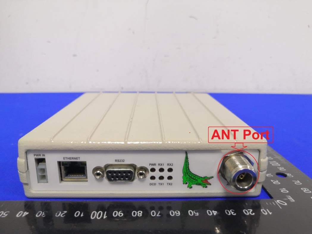
Alligator Communications FCC ID: JIL2888 External Photographs
ID Label/Location Info
Alligator Communications FCC ID: JIL2888 ID label and Label Location This device complies with Part 15 of the FCC Rules. Operation is subject to the following two conditions: (1) this device may not cause harmful interference, and (2) this device must accept any interference received, including interference that may cause undesired operation Alligator Communications Inc. FCC ID: JIL2888
Internal Photos
Alligator Communications FCC ID: JIL2888 Internal Photographs Top cover removed bottom cover removed
Operational Description
Maintenance 5- 26 4.1 GENERAL DISCUSSION The 2888 radio is a half duplex transceiver intended for use as either a Master or a Remote Station Radio unit in a Wireless SCADA data transmission system. 4.2 MICROPROCESSOR OPERATION The microprocessor, U-203 is the "brain" of the 2888 radio. It enables a computer to communicate with the 2888 radio and enables the operator to "see" everything that the Remote "sees", such as diagnostics. The microprocessor also allows the operator to observe the operating parameters, frequency, power output, reverse power, PLL voltages, the power output level and the frequency offset. These and other operations may be performed locally or through the RF link. 4.3 FUNCTIONS OF THE 2888 RADIO The Alligator Model 2888 offers diagnostic parameters which aid the user in troubleshooting potential problems in the SCADA network. The Model 2888 also offers options which enable the radio to be a “smart” radio. It may also be configured for use in a variety of different configurations. The Alligator Advanced Diagnostics Software can read and/or modify all of the following parameters for each responding Model 2888 Radio. 4.3.1 Diagnostic Parameters Parameter Description Alarm Status Alerts the user that one or more of the diagnostic parameters are not within the safety limits. Received Signal Strength Indicator (RSSI) An indicator of a Remote’s signal strength. Forward Power The amount of power the carrier frequency is being transmitted. Reverse Power An indicator of the quality of the Remote Radio’s antenna. A reverse power reading greater than one-third of the forward power reading indicates that the antenna is degrading, or that cables and connectors are not properly connected to the radio. 4.0 Theory of Operation Maintenance 5- 27 Parameter Description Supply Voltage The recommended power supply to the Remote Radio should be no less than 11 V and no more than 16V, with 13.8V the nominal voltage. A power supply capable of supplying at least 2 amps is required for proper operation of the radio. PLL Voltages The voltage readings of the two Phase-Locked-Loops (PLL1 & PLL2). For safe radio operation, this voltage should be between 0.1 to 4 Volts. Internal Temperature Serves as a “thermometer” for the environment surrounding the radio. Also serves as a sign if something is wrong with the Remote Radio. Table 4.2 Diagnostic Parameters Descriptions 4.3.2 Alarm Limits and Conditions The Alligator Advanced Diagnostics Software provides the user with the capability to set the desired safety limits for each diagnostic parameter. The user can set high and low limits for Supply Voltage, PLL1 Voltage, PLL2 Voltage, Internal Temperature, Forward Power, and event (squelch, PTT, Time- out) counters. Should any of these parameters fall outside its safety limits, an alarm condition will be generated and displayed by the Remote Radio. An alarm condition will also exist if the Reverse Power (reflected power) reading exceeds 30% of the Forward Power reading, or if the VSWR (Voltage Standing Wave Ratio) reaches an unsafe value. 4.3.3 Operating Parameters The Alligator Advanced Diagnostics Software enables the user to configure each Remote Radio to operate in a certain configuration. Each Remote Radio can be configured to operate under any of the following configurations: Parameter Description PTT Dekey Time (0-255 msec) Whenever the 2888 Radio turns on its transmitter, the dekey time is the number of milliseconds the transmitter stay…
Text truncated - open the document above for the full version.
Contact Information
Applicant
Henry C Wu(General Manager)
Test Firm
Compliance Certification Services IncSteve Cheng
Technical Specifications
| # | Rule Parts | Frequency Range | Power Output | Emission | Tolerance |
|---|---|---|---|---|---|
| 4 | 101 | 928 MHz - 929 MHz | 5.89 W | 13K7F1D | 0.00015 % |
Other Applications from Alligator Communications Inc
JIL2788B
Jan 03, 2020787-788MHz Licensed MAS Radio
Equipment Class
TNB - Licensed Non-Broadcast Station TransmitterJIL1888B
Jun 02, 1998TNB - Licensed Non-Broadcast Station Transmitter
Equipment Class
TNB - Licensed Non-Broadcast Station TransmitterJIL1800B
Mar 17, 1998Single Channel Mode
Equipment Class
TNB - Licensed Non-Broadcast Station TransmitterJIL1800
Feb 02, 1992TNB - Licensed Non-Broadcast Station Transmitter
Equipment Class
TNB - Licensed Non-Broadcast Station TransmitterJIL1800R
Feb 02, 1992CXX - Communications Rcvr for use w/ licensed Tx and CBs
Equipment Class
CXX - Communications Rcvr for use w/ licensed Tx and CBs