JNZVR0002TV Cam HD
Logitech Far East Ltd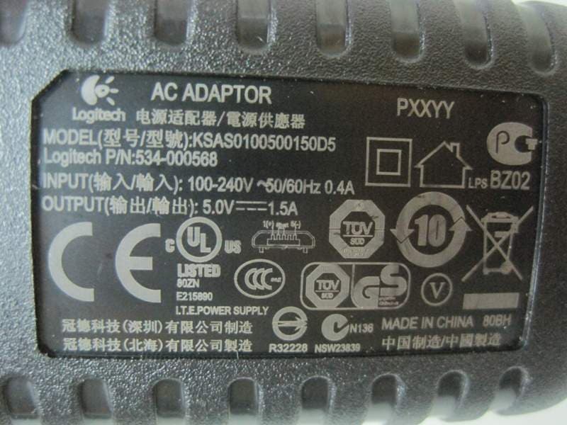
Click to zoom
Application Details
- Equipment Class
- DTS - Digital Transmission System
- Date of Grant
- Jul 23, 2012
- Application Purpose
- Original Equipment
- Date of Application
- Jul 23, 2012
- Equipment Note
- TV Cam HD
- Frequency Range
- 2412.00000000 - 2462.00000000
- Company
- Logitech Far East Ltd
- Country
- Taiwan
Documents & Files
Document Text
Text extracted from the exhibit documents filed with the FCC. Open a document above to read the original.
Users Manual
Setup Guide Logitech® TV Cam HD 2 English 3 繁體中文 11 한국어 19 Contents English 3 1 678910 1516 13 14 17 20 21 19 18 5 1112 4 2 3 4 English Know your product The TV Cam and accessories 1. Microphones (4) 2. Message indicator 3. IR sensor 4. Activity light 5. Camera lens 6. HDMI® port 7. Ethernet port 8. Micro-USB power port 9. Reset 10. Call ringer 11. TV clip/stand 12. Tripod mount 13. AC power adapter 14. HDMI cable Remote control 15. Call/Answer Make a call or answer a call. 16. Hang up/Ignore End or ignore a call. 17. Back Return to the previous screen. 18. Home Go to the Contacts page. 19. OK Select highlighted option. 20. Directional pad Navigate up, down, left, or right. 21. Battery compartment Battery is preinstalled. English 5 Set up your product 1 2 Place the TV Cam on the TV or on a surface near the TV screen so that there are no obstructions. Connect an HDMI cable to the back of the TV Cam and into your TV. 6 English 3 Connect the TV cam to your network using an Ethernet cable. (Cable not included.) Skip this step if using Wi-Fi®. 4 Connect AC Power Adapter into the Micro-USB power port of the TV Cam. English 7 5 6 Turn on your TV. 7 Using your TV remote, select the HDMI source input where you have plugged your TV Cam into. 8 Follow the on-screen instructions to finish setup using the TV Cam remote control. You may need the following information to complete setup: • Wi-Fi network name (if using Wi-Fi) • Wi-Fi password (if using Wi-Fi) • Your Skype login information Visit Product Central There’s more information and support online for your product. Take a moment to visit Product Central to learn more about your new TV Cam. Browse online articles for setup help, usage tips, or information about additional features. If your TV Cam has optional software, learn about its benefits and how it can help you customize your product. Connect with other users in our Community Forums to get advice, ask questions, and share solutions. At Product Central, you’ll find a wide selection of content: • Tutorials • Troubleshooting • Support community • Software downloads • Online documentation • Warranty information • Spare parts (when available) Go to www.logitech.com/support/tvcamhd 8 English Use your product When using the TV Cam, your TV must be on and set to the correct HDMI input. When you receive a call, the ringer on the TV Cam sounds and the Activity light flashes. During a video call, the Activity light glows solid white to let you know you’re on camera. If you miss a call or you don’t pick up, the Message indicator light turns on, reminding you to check Call History. The Home page My Skype profile Skype contacts Call history Dial pad Settings Use on-screen controls Zoom/Pan Mute audio Answer/Hang up Freeze video Preview window For more information on using your TV Cam and making calls, go to www.logitech.com/ support/tvcamhd English 9 Troubleshooting The software download fails or the TV Cam freezes during setup • Disconnect and then reconnect the AC power adapter to restart the TV Cam. • If the restart fails, you will need to restore TV Cam’s default settings. Unplug the micro-USB cable. Insert a pin in the reset hole to hold down the reset button while you reconnect the micro-USB cable. There is no video or audio • Your TV must be turned on and its volume set to an audible level. • Use your TV remote to select the HDMI input used by the TV Cam. • Check all of the TV Cam cable connections, including HDMI, power, and Ethernet. • Is your modem or router working properly? Is there a disruption in your Internet service? • Your caller could be experiencing Internet or equipment issues that contributes to the problem. I can’t get Wi-Fi to work with my TV Cam • Check your Wi-Fi signal strength using a computer or mobile device. If the signal is weak, move your router or modem closer to your TV, or you may need to use an Ethernet connection. • Your Wi-Fi router or modem must be 802.11 g/n compatible. I forgot my Wi-Fi user name and password • Refer to your modem or router documentation or contact the manufacturer for assistance. For more detailed network troubleshooting, go to www.logitech.com/support/tvcamhd 10 English There is poor audio/video quality • Is the sound on mute? Try turning up the volume on your TV. • Reduce excessive background noise. • If there’s an echo on either side of the call, make sure there is at least 20 cm between microphones and speakers. • Increase or decrease room lighting. Avoid sitting or standing with your back to a sun-lit window or bright lamp. • Your TV cam’s video image is optimized for a 1m to 4m range (or 3–12 feet). Images appear at their best within this range. • Bandwidth, packet loss and other connection elements can contribute to video quality and image resolution. For more detailed network troubleshooting, go to www.logitech.com/ support/tvcamhd I’ve forgotten my Skype user name and password • For help, go to support.skype.com. Clear Personal Data • Before transferring ownership of the TV Cam, be sure to clear your personal information from the device. Go to Settings > General > Clear user data. 繁體中文 11 1 678910 1516 13 14 17 20 21 19 18 5 1112 4 2 3 12 繁體中文 認識產品 TV Cam 和配件 1. 麥克風 (4) 2. 訊息指示燈 3. 紅外線感應器 4. 動作指示燈 5. 攝影機鏡頭 6. HDMI® 連接埠 7. 乙太網路連接埠 8. 微型 USB 電源連接埠 9. 重設 10. 來電鈴聲 11. 電視夾扣/立架 12. 三腳架托環 13. 電源轉接器 14. HDMI 連接線 遙控器 15. 撥打/接聽 撥打電話或接聽電話。 16. 掛斷/忽略 結束通話或忽略來電。 17. 返回 回到上一個畫面。 18. 首頁 進入「聯絡人」頁面。 19. 確定 選取醒目提示的選項。 20. 方向板 上、下、左、右瀏覽。 21. 電池匣 已預先裝妥電池。 繁體中文 13 設定產品 1 2 將 TV Cam 放在電視上或靠近電視螢幕的平面 上,避免有任何障礙物。 將 HDMI 連接線的兩端分別插入 TV Cam 背面 及電視。 14 繁體中文 3 使用乙太網路連接線將 TV Cam 連接至網路 (連 接線需另購)。如使用 Wi-Fi®,請跳過此步驟。 4 將 AC 電源轉接器插入 TV Cam 的微型 USB 電 源連接埠中。 繁體中文 15 5 6 開啟電視電源。 7 使用電視遙控器選取 TV Cam 所使用的 HDMI 來源輸入。 8 依照畫面指示操作,使用 TV Cam 遙控器 完成設定。 您可能需要下列資訊才能完成設定: • Wi-Fi 網路名稱 (若使用 Wi-Fi) • Wi-Fi 密碼 (若使用 Wi-Fi) • Skype 登入資訊 造訪「產品中心」 您的產品還有更多產品相關資訊與支援。請抽 空造訪「產品中心」,深入瞭解新 TV Cam。 請瀏覽線上文章,瞭解設定說明、使用秘訣, 或是其他功能的相關資訊。如果您的 TV Cam 隨附選用軟體,您可以深入瞭解軟體優點及該 軟體如何協助您自訂產品。 您還可以和「社群論壇」中的其他使用者保持 聯繫以獲得建…
Text truncated - open the document above for the full version.
External Photos
SPORTON International Inc. PAGE NUMBER : A1 OF A12 TEL : 886-2-2696-2468 ISSUED DATE : Jul. 20 , 2012 FAX : 886-2-2696-2255 APPENDIX A. Photographs of EUT SPORTON International Inc. PAGE NUMBER : A2 OF A12 TEL : 886-2-2696-2468 ISSUED DATE : Jul. 20 , 2012 FAX : 886-2-2696-2255 SPORTON International Inc. PAGE NUMBER : A3 OF A12 TEL : 886-2-2696-2468 ISSUED DATE : Jul. 20 , 2012 FAX : 886-2-2696-2255 SPORTON International Inc. PAGE NUMBER : A4 OF A12 TEL : 886-2-2696-2468 ISSUED DATE : Jul. 20 , 2012 FAX : 886-2-2696-2255 Adapter 1 Brand Name: LOGITECH Model No.: SPORTON International Inc. PAGE NUMBER : A5 OF A12 TEL : 886-2-2696-2468 ISSUED DATE : Jul. 20 , 2012 FAX : 886-2-2696-2255 Adapter 2 Brand Name:LOGITECH Model No.: AD835327 SPORTON International Inc. PAGE NUMBER : A6 OF A12 TEL : 886-2-2696-2468 ISSUED DATE : Jul. 20 , 2012 FAX : 886-2-2696-2255 SPORTON International Inc. PAGE NUMBER : A7 OF A12 TEL : 886-2-2696-2468 ISSUED DATE : Jul. 20 , 2012 FAX : 886-2-2696-2255 Adapter 3 Brand Name:LOGITECH Model No.: KSAS0100500150D5 SPORTON International Inc. PAGE NUMBER : A8 OF A12 TEL : 886-2-2696-2468 ISSUED DATE : Jul. 20 , 2012 FAX : 886-2-2696-2255 Adapter 4 Brand Name:LOGITECH Model No.: KSAS0100500150HU SPORTON International Inc. PAGE NUMBER : A9 OF A12 TEL : 886-2-2696-2468 ISSUED DATE : Jul. 20 , 2012 FAX : 886-2-2696-2255 SPORTON International Inc. PAGE NUMBER : A10 OF A12 TEL : 886-2-2696-2468 ISSUED DATE : Jul. 20 , 2012 FAX : 886-2-2696-2255 SPORTON International Inc. PAGE NUMBER : A11 OF A12 TEL : 886-2-2696-2468 ISSUED DATE : Jul. 20 , 2012 FAX : 886-2-2696-2255 SPORTON International Inc. PAGE NUMBER : A12 OF A12 TEL : 886-2-2696-2468 ISSUED DATE : Jul. 20 , 2012 FAX : 886-2-2696-2255
Internal Photos
SPORTON International Inc. PAGE NUMBER : A1 OF A10 TEL : 886-2-2696-2468 ISSUED DATE : Jul. 20 , 2012 FAX : 886-2-2696-2255 APPENDIX A. Photographs of EUT SPORTON International Inc. PAGE NUMBER : A2 OF A10 TEL : 886-2-2696-2468 ISSUED DATE : Jul. 20 , 2012 FAX : 886-2-2696-2255 SPORTON International Inc. PAGE NUMBER : A3 OF A10 TEL : 886-2-2696-2468 ISSUED DATE : Jul. 20 , 2012 FAX : 886-2-2696-2255 SPORTON International Inc. PAGE NUMBER : A4 OF A10 TEL : 886-2-2696-2468 ISSUED DATE : Jul. 20 , 2012 FAX : 886-2-2696-2255 SPORTON International Inc. PAGE NUMBER : A5 OF A10 TEL : 886-2-2696-2468 ISSUED DATE : Jul. 20 , 2012 FAX : 886-2-2696-2255 SPORTON International Inc. PAGE NUMBER : A6 OF A10 TEL : 886-2-2696-2468 ISSUED DATE : Jul. 20 , 2012 FAX : 886-2-2696-2255 SPORTON International Inc. PAGE NUMBER : A7 OF A10 TEL : 886-2-2696-2468 ISSUED DATE : Jul. 20 , 2012 FAX : 886-2-2696-2255 SPORTON International Inc. PAGE NUMBER : A8 OF A10 TEL : 886-2-2696-2468 ISSUED DATE : Jul. 20 , 2012 FAX : 886-2-2696-2255 SPORTON International Inc. PAGE NUMBER : A9 OF A10 TEL : 886-2-2696-2468 ISSUED DATE : Jul. 20 , 2012 FAX : 886-2-2696-2255 SPORTON International Inc. PAGE NUMBER : A10 OF A10 TEL : 886-2-2696-2468 ISSUED DATE : Jul. 20 , 2012 FAX : 886-2-2696-2255
RF Exposure Info
Report No.: FR261456 FCC ID: JNZVR0002 Page No. : C1 of C3 Appendix C. Maximum Permissible Exposure Report No.: FR261456 FCC ID: JNZVR0002 Page No. : C2 of C3 1. Maximum Permissible Exposure 1.1. Applicable Standard Systems operating under the provisions of this section shall be operated in a manner that ensures that the public is not exposed to radio frequency energy levels in excess limit for maximum permissible exposure. In accordance with 47 CFR FCC Part 2 Subpart J, section 2.1091 this device has been defined as a mobile device whereby a distance of 0.25 m normally can be maintained between the user and the device. (A) Limits for Occupational / Controlled Exposure Frequency Range (MHz) Electric Field Strength (E) (V/m) Magnetic Field Strength (H) (A/m) Power Density (S) (mW/ cm²) Averaging Time |E|²,|H|² or S (minutes) 0.3-3.0 614 1.63 (100)* 6 3.0-30 1842 / f 4.89 / f (900 / f)* 6 30-300 61.4 0.163 1.0 6 300-1500 F/300 6 1500-100,000 5 6 (B) Limits for General Population / Uncontrolled Exposure Frequency Range (MHz) Electric Field Strength (E) (V/m) Magnetic Field Strength (H) (A/m) Power Density (S) (mW/ cm²) Averaging Time |E|²,|H|² or S (minutes) 0.3-1.34 614 1.63 (100)* 30 1.34-30 824/f 2.19/f (180/f)* 30 30-300 27.5 0.073 0.2 30 300-1500 F/1500 30 1500-100,000 1.0 30 Note: f = frequency in MHz ; *Plane-wave equivalent power density 1.2. MPE Calculation Method E (V/m) = d GP30 Power Density: Pd (W/m²) = 377 2 E E = Electric field (V/m) P = Average RF output power (W) G = EUT Antenna numeric gain (numeric) d = Separation distance between radiator and human body (m) The formula can be changed to Pd = 2 377 30 d GP From the EUT RF output power, the minimum mobile separation distance, d=0.2m, as well as the gain of the used antenna, the RF power density can be obtained. Report No.: FR261456 FCC ID: JNZVR0002 Page No. : C3 of C3 1.3. Calculated Result and Limit Antenna Type : Printed Antenna Max Conducted Power for IEEE 802.11b : 13.68 dBm Antenna Gain (dBi) Antenna Gain (numeric) Average Output Power (dBm) Average Output Power (mW) Power Density (S) (mW/cm²) Limit of Power Density (S) (mW/cm²) Test Result 3.00 1.9953 13.6800 23.3346 0.009267 1 Complies
Test Report
SPORTON International Inc. No. 52, Hwa Ya 1st Rd., Kwei-Shan Hsiang, TaoYuan Hsien, Taiwan, R.O.C. Ph: 886-3-327-3456 / FAX: 886-3-327-0973 / www.sporton.com.tw Report Format Version: 01 FCC RADIO TEST REPORT Applicant’s company LOGITECH FAR EAST LTD. Applicant Address #2 Creation Rd. 4, Science-Based Ind. Park Hsinchu Taiwan, R.O.C. FCC ID JNZVR0002 Manufacturer’s company LOGITECH FAR EAST LTD. Manufacturer Address #2 Creation Rd. 4, Science-Based Ind. Park Hsinchu Taiwan, R.O.C. Product Name TV Cam HD Brand Name Logitech Model Name V-R0002 Test Rule Part(s) 47 CFR FCC Part 15 Subpart C § 15.247 Test Freq. Range 2400 ~ 2483.5MHz Received Date Jun. 14, 2012 Final Test Date Jul. 17, 2012 Submission Type Original Equipment Statement Test result included is only for the IEEE 802.11n, IEEE 802.11b/g part of the product. The test result in this report refers exclusively to the presented test model / sample. Without written approval of SPORTON International Inc., the test report shall not be reproduced except in full. The measurements and test results shown in this test report were made in accordance with the procedures and found in compliance with the limit given in ANSI C63.10-2009 and 47 CFR FCC Part 15 Subpart C. The test equipment used to perform the test is calibrated and traceable to NML/ROC. Report No.: FR261456 Report Format Version: 01 Page No. : i of ii FCC ID: JNZVR0002 Issued Date :Jul. 20, 2012 Table of Contents 1. CERTIFICATE OF COMPLIANCE ........................................................................................................................... 1 2. SUMMARY OF THE TEST RESULT ............................................................................................................................ 2 3. GENERAL INFORMATION..................................................................................................................................... 3 3.1. Product Details ........................................................................................................................................................................................... 3 3.2. Accessories ................................................................................................................................................................................................. 5 3.3. Table for Filed Antenna ............................................................................................................................................................................. 5 3.4. Table for Carrier Frequencies ................................................................................................................................................................... 6 3.5. Table for Test Modes .................................................................................................................................................................................. 7 3.6. Table for Testing Locations........................................................................................................................................................................ 7 3.7. Table for Supporting Units ......................................................................................................................................................................... 8 3.8. Table for Parameters of Test Software Setting ....................................................................................................................................... 9 3.9. Test Configurations................................................................................................................................................................................... 10 4. TEST RESULT......................................................................................................................................................... 12 4.1. AC Power Line Conducted Emissions Measurement ......................................................................................................................... 12 4.2. Peak Output Power Measurement ....................................................................................................................................................... 16 4.3. Average Output Power Measurement................................................................................................................................................. 19 4.4. Power Spectral Density Measurement.................................................................................................................................................. 22 4.5. 6dB Spectrum Bandwidth Measurement ............................................................................................................................................. 28 4.6. Radiated Emissions Measurement......................................................................................................................................................... 33 4.7. Band Edge Emissions Measurement...................................................................................................................................................... 48 4.8. Antenna Requirements ........................................................................................................................................................................... 55 5. LIST OF MEASURING EQUIPMENTS .................................................................................................................... 56 6. TEST LOCATION.................................................................................................................................................. 58 7. TAF CERTIFICATE OF ACCREDITATION.............................................................................................................. 59 APPENDIX A. PHOTOGRAPHS OF EUT ....................................................................…
Text truncated - open the document above for the full version.
Test Setup Photos
Report No.: FR261456 FCC ID: JNZVR0002 Page No. : B1 of B5 Appendix B. Test Photos Report No.: FR261456 FCC ID: JNZVR0002 Page No. : B2 of B5 1. Photographs of Conducted Emissions Test Configuration Test Mode : Mode 2 FRONT VIEW REAR VIEW Report No.: FR261456 FCC ID: JNZVR0002 Page No. : B3 of B5 2. Photographs of Radiated Emissions Test Configuration Test Configuration: 9kHz ~30MHz FRONT VIEW REAR VIEW Report No.: FR261456 FCC ID: JNZVR0002 Page No. : B4 of B5 Test Configuration: 30MHz~1GHz / Test Mode : Mode 1 FRONT VIEW REAR VIEW Report No.: FR261456 FCC ID: JNZVR0002 Page No. : B5 of B5 Test Configuration: Above 1GHz FRONT VIEW REAR VIEW
Contact Information
Applicant
Rick Lien(Head of Product Compliance)
Test Firm
Sporton International Inc.Alex Chen
Technical Specifications
| # | Rule Parts | Frequency Range | Power Output |
|---|---|---|---|
| 1 | 15C | 2.41 GHz - 2.46 GHz | 123.90 mW |
Other Applications from Logitech Far East Ltd
JNZYR0126
Jul 30, 2026Wireless Keyboard
Equipment Class
DTS - Digital Transmission SystemJNZYR0116
Jul 30, 2026Wireless Keyboard
Equipment Class
DTS - Digital Transmission SystemJNZYR0115
Jul 30, 2026Wireless Keyboard
Equipment Class
DTS - Digital Transmission SystemJNZMR0143
Jul 21, 2026Wireless Mouse
Equipment Class
DTS - Digital Transmission SystemJNZMR0136
Jul 09, 2026Wireless Mouse
Equipment Class
DTS - Digital Transmission System