JNZXR0001Squeezebox Radio
Logitech Far East Ltd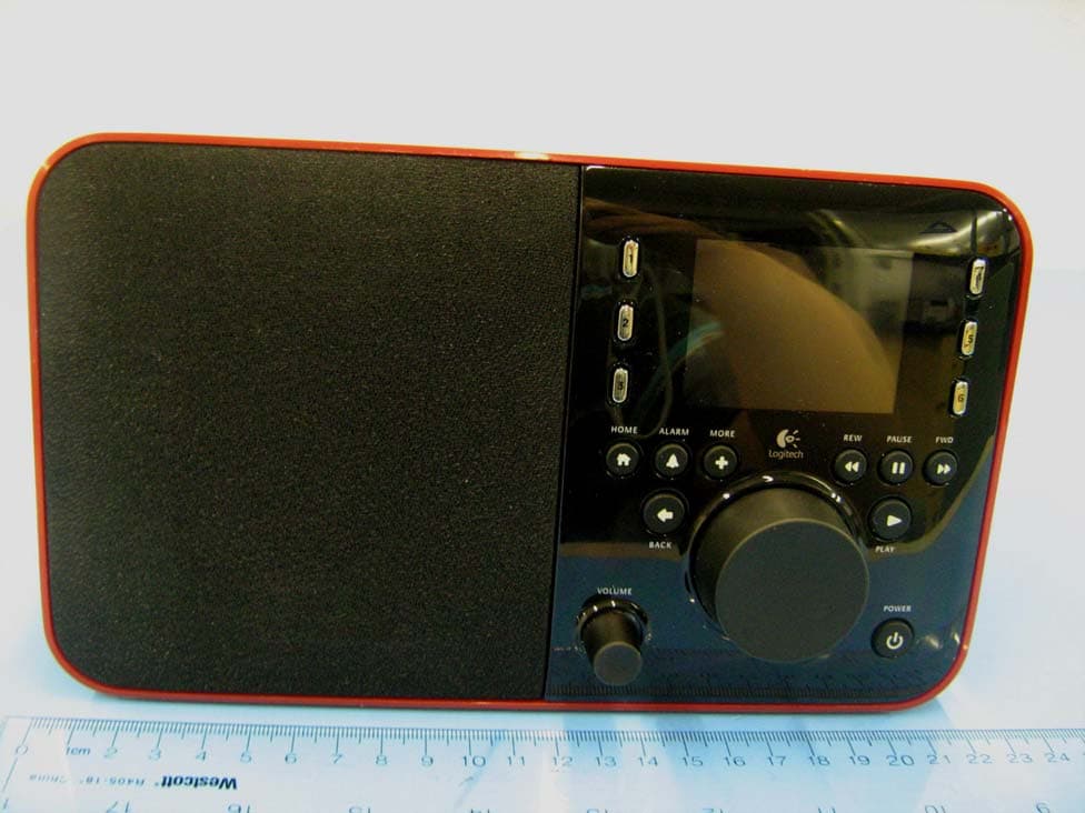
Click to zoom
Application Details
- Equipment Class
- DTS - Digital Transmission System
- Date of Grant
- Aug 19, 2009
- Application Purpose
- Original Equipment
- Date of Application
- Aug 19, 2009
- Equipment Note
- Squeezebox Radio
- Frequency Range
- 2412.00000000 - 2462.00000000
- Company
- Logitech Far East Ltd
- Country
- Taiwan
Documents & Files
Document Text
Text extracted from the exhibit documents filed with the FCC. Open a document above to read the original.
Users Manual
2 3 1 5 6 4 HOMEALARM BACK VOLUME POWER PLAY MORE Now Playing 1 of 12 REWPAUSEFWD Quick start guide 2 3 1 5 6 4 Now Playing 1 of 12 Squeezebox Radio Rechargeable battery pack Remote control Power adapter with removable plug 3.5mm audio cord – Connects your iPod® or MP3 player Opt ional Accessory Pack (www.logitech.com) If you want to use Squeezebox Radio with headphones or powered speakers. Required for wired network option only To listen to music stored on your iPod or MP3 player, connect using the included cord. Squeezebox ™ Radio Wi-Fi Internet Radio Logitech ® For more information about your Squeezebox, go to www.mysqueezebox.com. For phone support, call: • Monday through Friday, from 6:00 a.m. to 9:00 p.m. (0600-2100) Pacific time • Saturday and Sunday, from 7:00 a.m. to 5:00 p.m. (0700-1700) Pacific time At the following numbers: +1 (877) 887-8889 (Toll-free in North America) +1 (646) 454-3237 (For all other countries) Getting help Thank you for purchasing a Logitech® Squeezebox™ Radio Wi-Fi Internet radio. We hope you have as much fun using it as we did creating it for you. This guide covers basic hardware setup. Once hardware setup is complete, the Squeezebox Radio screens will guide you through the rest of the setup process. The Troubleshooting section at the end of the guide covers issues that you might encounter during the setup process. For full documentation of Squeezebox Radio functionality, a feature guide is available at www.mysqueezebox.com. What you need to get started To start using your Squeezebox Radio, you will need: • A broadband Internet connection (for example, DSL or cable modem) • The name and password of your wireless network; or a wired Ethernet connection Package contents Find a good location The compact size of the Squeezebox Radio makes it very easy to enjoy music anywhere in your home or office. Just make sure the location has Wi-Fi coverage or an Ethernet connection and a power outlet (not required if you have the optional rechargeable battery pack). * Ethernet cable not included If you will be adding Squeezebox Radio to a wireless network, make sure that your Squeezebox is within range of your wireless network. If you will be setting up a wired connection, locate Squeezebox Radio within reach of an Ethernet jack. A typical Squeezebox Radio setup Plug in Squeezebox Connect Squeezebox Radio After plugging in your Squeezebox Radio, it will automatically turn on after a few seconds. Squeezebox Radio startup screen Squeezebox Radio at a glance Squeezebox Front ETHERNET Squeezebox Back POWER RECHARGEABLE BATTERY COMPARTMENT HEADPHONE BACK HOME MORE ALARM 3.5 mm LINE-IN VOLUME PLAY POWER PUSHBUTTON KNOB FORWARD PAUSE/STOP REWIND PRESET BUTTONS PRESET BUTTONS 2 1
External Photos
1.2 Product Under Test Photo Figure 8: External Photo of X-R0001 with AC Adapter Figure 9: External Photo of X-R0001 – Front View Figure 10: External Photo of X-R0001 – Rear View
Internal Photos
Figure 11: Part Photo of X-R0001 Figure 12: Internal Photo of X-R0001 - PCB Board (Front Side) Figure 13: Internal Photo of X-R0001 - PCB Board (Rear Side) TX Antenna Figure 14: Internal Photo of X-R0001 – I/O Connector (Top Side) Figure 15: Internal Photo of X-R0001 – I/O Connector (Bottom Side)
RF Exposure Info
1.1 Maximum Permissible Exposure 1.1.1 Test Methodology In this document, we try to prove the safety of radiation harmfulness to the human body for our product. The limit for Maximum Permissible Exposure (MPE) specified in FCC 1.1310 is followed. The Gain of the antenna used in this product is measured in a Semi-Anechoic Chamber, and also the maximum total power input to the antenna is measured. Through the Friis transmission formula and the maximum gain of the antenna, we can calculate the distance, away from the product, where the limit of MPE is reached. Although the Friis transmission formula is a far field assumption, the calculated result of that is an over-prediction for near field power density. We will take that as the worst case to specify the safety range. 1.1.2 RF Exposure Limit According to FCC 1.1310 table 1: The criteria listed in the following table shall be used to evaluate the environmental impact of human exposure to radio-frequency (RF) radiation as specified in 1.1307(b) LIMITS FOR MAXIMUM PERMISSIBLE EXPOSURE (MPE) Frequency Range (MHz) Electric Field Strength (V/m) Magnetic Field Strength (A/m) Power Density (mW/cm 2) Average Time (minutes) (A)Limits For Occupational / Control Exposures 300-1500 ... ... F/300 6 1500-100,000 ... ... 5 6 (B)Limits For General Population / Uncontrolled Exposure 300-1500 ... ... F/1500 6 1500-100,000 ... ... 1.0 30 F = Frequency in MHz 1.1.3 EUT Operating Condition The software provided by Manufacturer enabled the EUT to transmit data at lowest, middle and highest channel individually. 1.1.4 Classification The antenna of the product, under normal use condition, is at least 20cm away from the body of the user. Warning statement to the user for keeping at least 20cm or more separation distance with the antenna should be included in users manual. So, this device is classified as a Mobile Device. 1.1.5 Test Results 1.1.5.1 Antenna Gain The transmitting antenna was integrated. The antenna gain was -0.86dBi or 0.82 (numeric). 1.1.5.2 Output Power into Antenna & RF Exposure value at distance 20cm: Calculations for this report are based on highest power measurement. Limit for MPE (from FCC part 1.1310 table1) is 1.0 mW/cm 2 The highest measured EIRP power is +22.08dBm or 161.44mW Using the Friss transmission formula, the EIRP is Pout*G, and R is 20cm. Pd = 161.44 / (1600π) = 0.321mW/cm 2 , which is 0.6788 mW/cm 2 below to the limit. As originally tested, the EUT was found to be compliant to the requirements of the test standard(s). 1.1.6 Sample Calculation The Friis transmission formula: Pd = (Pout*G) / (4*π*R 2 ) Where; Pd = power density in mW/cm 2 Pout = output power to antenna in mW G = gain of antenna in linear scale π ≈ 3.1416 R = distance between observation point and center of the radiator in cm Ref. : David K. Cheng, Field and Wave Electromagnetics, Second Edition, Page 640, Eq. (11- 133).
Test Report
Report Number: 30981128.001 Page 1 of 97 EUT: Squeezebox Radio Model: X-R0001 EMC / Rev 8/20/2009 Emissions Test Report EUT Name: Squeezebox Radio Model No.: X-R0001 CFR 47 Part 15.247 2008 and RSS 210: 2007 Prepared for: Diane Lee Logitech Far East Ltd. Science Based Industrial Park (No. 2 Creation Road IV) Hsinchu, Taiwan Tel: (011) 886-35778241 Fax: (011) 886-35772146 Prepared by: TUV Rheinland of North America, Inc. 1279 Quarry Lane Pleasanton, CA 94566 Tel: (925) 249-9123 Fax: (925) 249-9124 http://www.tuv.com/ Report/Issue Date: 28 July 2009 Report Number: 30981128.001 Statement of Compliance Report Number: 30981128.001 Page 2 of 97 EUT: Squeezebox Radio Model: X-R0001 EMC / Rev 8/20/2009 Manufacturer: Logitech Far East Ltd. Science Based Industrial Park (No. 2 Creation Road IV) Hsinchu, Taiwan (011) 886-35778241 Requester / Applicant: Diane Lee Name of Equipment: Squeezebox Radio Model No. X-R0001 Type of Equipment: Intentional Radiator Application of Regulations: CFR 47 Part 15.247 2008 and RSS 210: 2007 Test Dates: 15 July 2009 to 24 July 2009 Guidance Documents: Emissions: AN C63.4: 2003 Test Methods: Emissions: AN C63.4: 2003 The electromagnetic compatibility test and documented data described in this report has been performed and recorded by TUV Rheinland, in accordance with the standards and procedures listed herein. As the responsible authorized agent of the EMC laboratory, I hereby declare that the equipment described above has been shown to be compliant with the EMC requirements of the stated regulations and standards based on these results. If any special accessories and/or modifications were required for compliance, they are listed in the Executive Summary of this report. This report must not be used to claim product endorsement by NVLAP or any agency of the U.S. Government. This report contains data that are not covered by NVLAP accreditation. This report shall not be reproduced except in full, without the written authorization of TUV Rheinland of North America. Jeremy Luong 24 July 2009 Conan Boyle 24 July 2009 Test Engineer Date NVLAP Signatory Date Industry Canada 500011-0 US5251 2932D-1 Table of Contents Report Number: 30981128.001 Page 3 of 97 EUT: Squeezebox Radio Model: X-R0001 EMC / Rev 8/20/2009 1 Executive Summary _______________________________________________________ 6 1.1 Scope______________________________________________________________________ 6 1.2 Purpose____________________________________________________________________ 6 1.3 Summary of Test Results _____________________________________________________ 6 1.4 Special Accessories __________________________________________________________ 7 1.5 Equipment Modifications _____________________________________________________ 7 2 Laboratory Information ____________________________________________________ 8 2.1 Accreditations & Endorsements _______________________________________________ 8 2.1.1 US Federal Communications Commission _______________________________________________8 2.1.2 NIST / NVLAP ____________________________________________________________________8 2.1.3 Canada – Industry Canada ___________________________________________________________8 2.1.4 Japan – VCCI _____________________________________________________________________8 2.1.5 Acceptance by Mutual Recognition Arrangement _________________________________________8 2.2 Test Facilities _______________________________________________________________ 9 2.2.1 Emission Test Facility______________________________________________________________9 2.2.2 Immunity Test Facility______________________________________________________________9 2.3 Measurement Uncertainty ____________________________________________________ 9 2.4 Calibration Traceability _____________________________________________________ 10 3 Product Information______________________________________________________ 11 3.1 Product Description ________________________________________________________ 11 3.2 Equipment Configuration ___________________________________________________ 11 3.3 Operating Mode ___________________________________________________________ 11 3.4 Unique Antenna Connector __________________________________________________ 12 3.4.1 Results _________________________________________________________________________12 4 Emissions ______________________________________________________________ 13 4.1 Output Power Requirements _________________________________________________ 13 4.1.1 Test Method _____________________________________________________________________13 4.1.2 Results _________________________________________________________________________14 4.2 Occupied Bandwidth________________________________________________________ 21 4.2.1 Test Method _____________________________________________________________________21 4.2.2 Results _________________________________________________________________________22 4.3 Band-edge Requirements ____________________________________________________ 35 4.4 Peak Power Spectral Density _________________________________________________ 59 4.4.1 Test Method _____________________________________________________________________59 4.4.2 Results _________________________________________________________________________60 4.5 Maximum Permissible Exposure ______________________________________________ 67 4.5.1 Test Methodology _________________________________________________________________67 4.5.2 RF Exposure Limit ________________________________________________________________67 4.5.3 EUT Operating Condition___________________________________________________________67 4.5.4 Classification ____________________________________________________________________68 4.5.5 Test Results__________________________________________________________________68 Table of Contents Report Number: 30981128.001 Page 4 of 97 EUT: Squeezebox Radio Model: X-R0001 EMC / Rev 8/20/2009 4.5.6 Sample Calculation ______________________________________________________…
Text truncated - open the document above for the full version.
Test Setup Photos
1 Photo 1.1 Test Setup Photo Figure 1: Photo of Test Setup for X-R0001, 30 MHz to 1000MHz (Front View) Figure 2: Photo of Test Setup for X-R0001, 30 to 1000 MHz (Rear View) Figure 3: Photo of Test Setup for X-R0001, 1GHz to 18GHz (Front View) Figure 4: Photo of Test Setup for X-R0001, 1GHz to 18GHz (Rear View) Figure 5: Photo of Test Setup for X-R0001, 18 GHz to 26GHz (Front View) Figure 6: Photo of Test Setup for X-R0001, 18 GHz to 26GHz (Rear View) Figure 7: Photo of Test Setup for X-R0001, AC Conducted Emission (Front View)
Contact Information
Applicant
Rick Lien(Head of Product Compliance)
Technical Contact
Logitech, Inc.Maurice Alou
[email protected]650-210-5730
Streaming Media Business Unit, 455 National Ave. · Mountain View, California
Test Firm
TUV Rheinland of North America Inc.Kent Chesley
Technical Specifications
| # | Rule Parts | Frequency Range | Power Output |
|---|---|---|---|
| 1 | 15C | 2.41 GHz - 2.46 GHz | 200.00 mW |
Other Applications from Logitech Far East Ltd
JNZYR0126
Jul 30, 2026Wireless Keyboard
Equipment Class
DTS - Digital Transmission SystemJNZYR0116
Jul 30, 2026Wireless Keyboard
Equipment Class
DTS - Digital Transmission SystemJNZYR0115
Jul 30, 2026Wireless Keyboard
Equipment Class
DTS - Digital Transmission SystemJNZMR0143
Jul 21, 2026Wireless Mouse
Equipment Class
DTS - Digital Transmission SystemJNZMR0136
Jul 09, 2026Wireless Mouse
Equipment Class
DTS - Digital Transmission System