JOK2257DTPDUAL TECH PENDANT (DTP)
Lifeline Systems, Inc.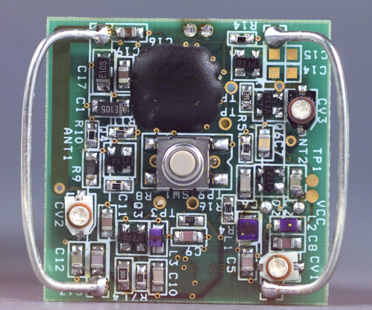
Click to zoom
Application Details
- Equipment Class
- DSC - Part 15 Security/Remote Control Transmitter
- Date of Grant
- Jun 08, 1999
- Application Purpose
- Original Equipment
- Date of Application
- Apr 20, 1999
- Equipment Note
- DUAL TECH PENDANT (DTP)
- Frequency Range
- 173.22500000 - 173.22500000
- Company
- Lifeline Systems, Inc.
- Country
- United States
Documents & Files

Document Text
Text extracted from the exhibit documents filed with the FCC. Open a document above to read the original.
Users Manual
Elcombe Systems Limited • 359 Terry Fox Drive Kanata • Ontario • Canada • K2K 2E7 Sales Phone 800.563.5564 • Support Phone 800.267.9004 DUAL TECH PENDANT USER’S MANUAL Elcombe Systems Limited • 359 Terry Fox Drive Kanata • Ontario • Canada • K2K 2E7 Sales Phone 800.563.5564 • Support Phone 800.267.9004 Dual Tech Pendant (DTP) A long life battery, designed to last for approximately five years powers the Elcombe Dual Tech Pendant (DTP) contained herein. When the battery runs low, or it is damaged, the entire pendant needs to be replaced. For a replacement pendant contact your dealer or Elcombe Systems Limited. Warning:There are no user-serviceable parts in the pendant. Do not try to replace batteries in the pendant. Do not dispose of the pendant in fire or expose it to temperatures in excess of 60° C (140° F). Do not crush, puncture, open, dismantle, or mechanically interfere with the pendant. Replacement In the event that repairs are needed to this equipment, contact your authorized dealer or Elcombe Systems Limited using one of the addresses listed below: Elcombe Systems Limited (USA) c/o Cole International Inc. 812 Proctor Avenue Ogdensburg, New York 13669 (315) 393-9981 Toll Free: 1 800 267-9004 (Technical Support) Elcombe Systems Limited (Canada) 359 Terry Fox Drive P.O. Box 72088 Kanata, Ontario K2K 2P4 (613) 591-5678 Toll Free: 1 800 267-9004 (Technical Support) Elcombe Systems Limited • 359 Terry Fox Drive Kanata • Ontario • Canada • K2K 2E7 Sales Phone 800.563.5564 • Support Phone 800.267.9004 Regulations This equipment generates, uses, and can radiate radio frequency energy and, if not installed and used in accordance with the instructions, may cause harmful interference to radio communications. This equipment has been tested and found to comply with the limits for a Class B Computing Device, pursuant to part 15 of FCC Rules. These limits are designed to provide reasonable protection against harmful interference in a residential installation. However, there is no guarantee that interference will not occur in a particular installation. This equipment has been tested and found to comply with the limits for a “Class B” digital device, pursuant to Part 15 of the FCC rules. These limits are designed to provide reasonable protection against harmful interference in a residential installation. This equipment generates, uses and can radiate radio frequency energy and, of not installed and used in accordance with the instructions, may cause harmful interference to radio communications. However, there is no guarantee that interference will not occur in a particular installation. If this equipment does cause harmful interference to radio or television reception, which can be determined by turning the equipment off and on, the user is encourage to try to correct the interference by one or more of the following measures: • reorient or relocate the receiving antenna • increase the separation between the equipment and receiver • connect the equipment into an outlet on a circuit different from that to which the receiver is connected • consult the dealer or an experience radio/TV technician for help Changes or modifications not expressly approved by Elcombe Systems Limited could void the user’s authority to operate the equipment. Operation is subject to the following two conditions: (1) This device may not cause interference, and (2) this device must accept any interference, including interference that may cause undesired operation in the device. L’utilisation de ce dispositif est autorisee seulement aux conditions suivants: (1) il ne doit pas produir de brouillage, et (2) l’utilisateur du dispositif doit etre pret a accepter tout brouillage radioelectrrique recu, meme si ce brouillage est susceptible de compromettre le fonctionnement du dispositif.
Operational Description
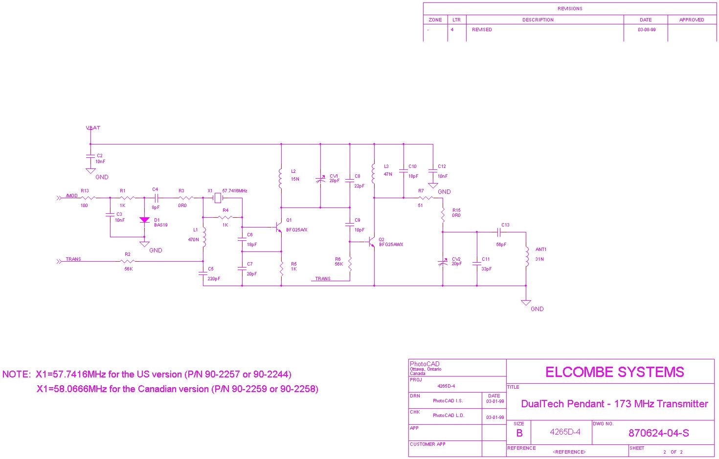
Dual Tech Pendant Short technical description The Dual Tech Pendant (DTP) is an emergency device which is intended to be carried by persons under risk. It is activated by a momentarily button depression. Once activated it sends a FM signal which lasts for 2 seconds which will be received by the nearest base station receiver in the area. The modulation signal is a data stream having the base- band frequency in the range of 500-700Hz. The DTP basically consist of three main blocks. The first one is a 900MHz active AM detector which acts like a receiver. The output of the detector provides a demodulated data stream that is fed to the second block. The second block is the processing unit. It is made by means of a low speed, low power microcontroller. This device interprets the incoming data and takes action accordingly; sometimes, transmission is part of the action. The third block is a VHF transmitter. The transmitter is crystal driven, it operates in VHF band (173.225 or 174.2 MHz) and it is frequency modulated. The role played by the pendant is a locating device one. The built in microcontroller stores one ID number as well as the Location Code, meaning the last well known location the pendant went through. If the button is depressed, the pendant will send a data stream including ID, Location information as well as data related to its functional status. The DTP is part of a small area Locating System. It works close to a number of beacons implemented using the 900MHz Wall Transmitter.
Parts List/Tune Up Info
DualTech Pendant - 900MHz Receiver Revised: Wednesday, April 07, 1999 Revision: ELCOMBE SYSTEMS Bill Of Materials April 13,1999 9:24:06Page1 ItemQuantity ReferencePart ______________________________________________ 11ANT131N 21ANT228N 31BT13V 43CV1,CV2,C720pF 52CV3,C9 10pF 62C17,C1 1uF 73C2,C3,C1210nF 81C48pF 91C5220pF 102C6,C10 18pF 112C18,C8 22pF 121C1133pF 131C1356pF 142C16,C19.1uF 151D1BAS19 161L1470N 171L215N 181L347N 191Q1BFG25A/X 204Q2,Q3,Q4,Q5BFG25AWX 213R1,R4,R51K 222R2,R656K 232R3,R15 0R0 241R751 251R8475K 261R915K 271R10182K 281R11681K 291R123.9M 301R13100 311R14340K 321R16100K 331R1710K 341SW1SW SPST 355TP1,TP2,TP3,TP4,TP5TEST POINT 361U1MSM6545 371X157.7416MHz 381X232KHz
Test Report
Master: ktlPT15231 Date: February 23, 1999 KTL Test Report:9R01440.1 Applicant:Elcombe Systems Limited PO Box 72088 359 Terry Fox Drive Kanata, Ontario K2K 2P4 Equipment Under Test:DUAL TECH PENDANT (DTP) (E.U.T.) FCC ID:J0K2257DTP In Accordance With:FCC Part 15, Subpart C For Low Power Transmitters Operating Periodically In The Band 40.66 - 40.77 MHz And Above 70 MHz Tested By:KTL Ottawa Inc. 3325 River Road, R.R. 5 Ottawa, Ontario K1V 1H2 Authorized By: T. Tidwell, Laboratory Manager Date: Total Number of Pages:29 KTL Ottawa FCC PART 15, SUBPART C FOR LOW POWER TRANSMITTERS PROJECT NO.: 9R01440.1 EQUIPMENT: DUAL TECH PENDANT (DTP) FCC ID: JOK2257DTP Page 2 of 27 Table of Contents Section 1. Summary of Test Results General Summary of Test Data Section 2. Equipment Under Test General Equipment Information Description of E.U.T. Modifications Incorporated in E.U.T. Theory of Operation Exercise Program Section 3. Equipment Configuration Equipment Configuration List Inter-Connection Cables Configuration of E.U.T. Section 4. Transmission Requirements Test Conditions Test Results Test Data Rationale for Compliance Graphs Section 5. Radiated Emissions Test Conditions Test Results Test Data - Radiated Emissions Radiated Photographs Pre-Scan Data Section 6. Occupied Bandwidth Test Conditions Test Results Test Data Graphs KTL Ottawa FCC PART 15, SUBPART C FOR LOW POWER TRANSMITTERS PROJECT NO.: 9R01440.1 EQUIPMENT: DUAL TECH PENDANT (DTP) FCC ID: JOK2257DTP Page 3 of 27 Table of Contents, continued Section 7. Frequency Tolerance Test Conditions Test Results Test Data Section 8. Periodic Alternate Field Strength Requirements Test Conditions Test Results Test Data Section 9. Powerline Conducted Emissions Test Conditions Test Results Test Data Section 10. Block Diagrams Conducted Emissions Radiated Prescan Outdoor Test Site for Radiated Emissions Occupied Bandwidth Section 11. Test Equipment List Annex A - Restricted Bands KTL Ottawa FCC PART 15, SUBPART C FOR LOW POWER TRANSMITTERS PROJECT NO.: 9R01440.1 EQUIPMENT: DUAL TECH PENDANT (DTP) FCC ID: JOK2257DTP Page 4 of 27 Section 1.Summary of Test Results Manufacturer:Elcombe Systems Limited Model No.:DTP Serial No.:001 General: All measurements are traceable to national standards. These tests were conducted on a sample of the equipment for the purpose of demonstrating compliance with Part 15, Subpart C, Paragraph 15.231. All tests were conducted using measurement procedure ANSI C63.4-1992. Radiated emissions are made on an open area test site. A description of the test facility is on file with the FCC. New SubmissionProduction Unit Class II Permissive ChangePre-Production Unit DS C Equipment Code THIS TEST REPORT RELATES ONLY TO THE ITEM(S) TESTED. THE FOLLOWING DEVIATIONS FROM, ADDITIONS TO, OR EXCLUSIONS FROM THE TEST SPECIFICATIONS HAVE BEEN MADE. See “ Summary of Test Data”. NVLAP LAB CODE: 100351-0 TESTED BY: _____________________________________ DATE: ___________________ Russell Grant, Technologist KTL Ottawa Inc. authorizes the above named company to reproduce this report provided it is reproduced in its entirety and for use by the company’s employees only. Any use which a third party makes of this report, or any reliance on or decisions to be made based on it, are the responsibility of such third parties. KTL Ottawa Inc. accepts no responsibility for damages, if any, suffered by any third party as a result of decisions made or actions based on this report. This report applies only to the items tested. KTL Ottawa FCC PART 15, SUBPART C FOR LOW POWER TRANSMITTERS PROJECT NO.: 9R01440.1 EQUIPMENT: DUAL TECH PENDANT (DTP) FCC ID: JOK2257DTP Page 5 of 27 Summary Of Test Data Name of TestParagraph NumberResults Transmission Requirements15.231(a)Complies Radiated Emissions15.231(b)Complies Occupied Bandwidth15.231(c)Complies Frequency Tolerance15.231(d)Not Applicable Periodic Alternate Field Strength Requirements15.231(e)Not Applicable Powerline Conducted Emissions15.207Not Applicable Footnotes For N/A’s: Test Conditions: Indoor Temperature: 20 °C Humidity:20 °C Outdoor Temperature: 20 °C Humidity:20 % KTL Ottawa FCC PART 15, SUBPART C FOR LOW POWER TRANSMITTERS PROJECT NO.: 9R01440.1 EQUIPMENT: DUAL TECH PENDANT (DTP) FCC ID: JOK2257DTP Page 6 of 27 Section 2.Equipment Under Test (E.U.T.) General Equipment Information Frequency Range: 173.225 MHz Operating Frequency(ies) of Sample: 173.225 MHz Type of Emission: Narrow Band FM Emission Designator: 5K92F1D Supply Power Requirement: Batteries Duty Cycle Calculation: Not applicable. The pendant emits one 3.1 second pulse when the push button is pressed. KTL Ottawa FCC PART 15, SUBPART C FOR LOW POWER TRANSMITTERS PROJECT NO.: 9R01440.1 EQUIPMENT: DUAL TECH PENDANT (DTP) FCC ID: JOK2257DTP Page 7 of 27 KTL Ottawa FCC PART 15, SUBPART C FOR LOW POWER TRANSMITTERS PROJECT NO.: 9R01440.1 EQUIPMENT: DUAL TECH PENDANT (DTP) FCC ID: JOK2257DTP Page 8 of 27 KTL Ottawa FCC PART 15, SUBPART C FOR LOW POWER TRANSMITTERS PROJECT NO.: 9R01440.1 EQUIPMENT: DUAL TECH PENDANT (DTP) FCC ID: JOK2257DTP Page 9 of 27 Description of E.U.T. The DUAL TECH Pendant (DTP) is an emergency device which is intended to be carried by persons at risk. It is activated by a momentary button depression. Once activated it sends an FM signal which lasts for 3.2 seconds which will be received by the nearest base station receiver in the area. Modifications Incorporated in E.U.T. The EUT has not been modified from what is described by the brand name and unique type identification stated above. KTL Ottawa FCC PART 15, SUBPART C FOR LOW POWER TRANSMITTERS PROJECT NO.: 9R01440.1 EQUIPMENT: DUAL TECH PENDANT (DTP) FCC ID: JOK2257DTP Page 10 of 27 Theory of Operation The E.U.T. is a narrow band FM transmitter. KTL Ottawa FCC PART 15, SUBPART C FOR LOW POWER TRANSMITTERS PROJECT NO.: 9R01440.1 EQUIPMENT: DUAL TECH PENDANT (DTP) FCC ID: JOK2257DTP Page 11 of 27 Justification The E.U.T. was configured for testing as per typical installation. The fol…
Text truncated - open the document above for the full version.
Contact Information
Applicant
Clyde Dottin(Manager, Engineering Services)
Technical Contact
ELCOMBE SYSTEMS LTD.GABRIEL PATULEA
[email protected]613-591-5678
359 TERRY FOX DRIVE · KANATA · Canada
Non-Technical Contact
ELCOMBE SYSTEMS LTD.KORY NEIL
[email protected]613-591-5678
Test Firm
Nemko Canada Inc.Stuart Beck
Technical Specifications
| # | Rule Parts | Frequency Range | Power Output |
|---|---|---|---|
| 1 | 15C | 173.225 MHz - 173.225 MHz | - |
Other Applications from Lifeline Systems, Inc.

JOK90-2359
Sep 07, 2000Smoke Alarm
Equipment Class
DSC - Part 15 Security/Remote Control TransmitterJOK90-2015-01
Jan 12, 1994CYY - Communications Receiver used w/Pt 15 Transmitter
Equipment Class
CYY - Communications Receiver used w/Pt 15 TransmitterJOK902023UTX
Dec 07, 1992Universal Transmitter
Equipment Class
DSC - Part 15 Security/Remote Control TransmitterJOK90-1311
Apr 13, 1992Security System Transmitter
Equipment Class
DSC - Part 15 Security/Remote Control TransmitterJOK90-1532
Apr 13, 1992Security System Transmitter
Equipment Class
EST - Unkown (From ALTOS)