JOZWHF430-PWireless Duplex Voice Transmitter
Automatic Manufacturing Ltd
Click to zoom
Application Details
- Equipment Class
- DXX - Part 15 Low Power Communication Device Transmitter
- Date of Grant
- Aug 18, 2002
- Application Purpose
- Original Equipment
- Date of Application
- Aug 18, 2002
- Equipment Note
- Wireless Duplex Voice Transmitter
- Frequency Range
- 925.00000000 - 928.00000000
- Company
- Automatic Manufacturing Ltd
- Country
- Hong Kong
Documents & Files
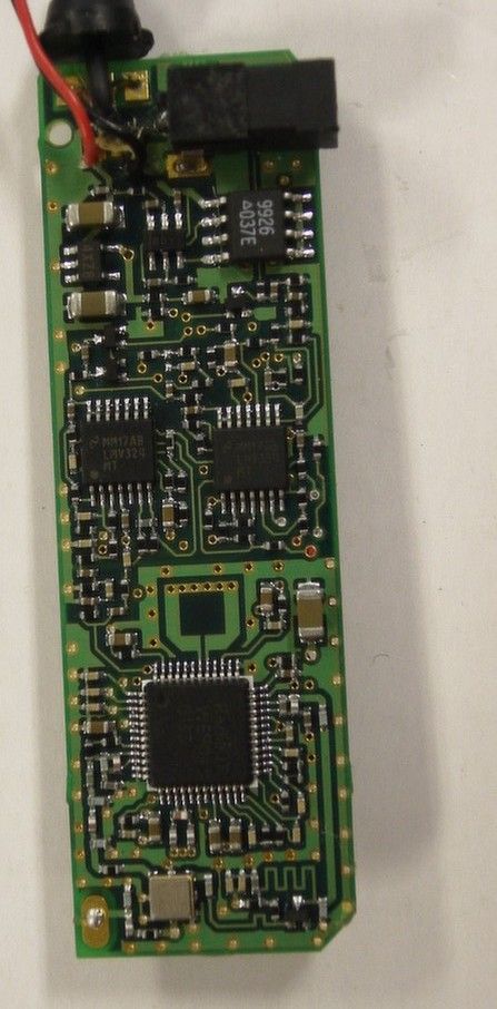
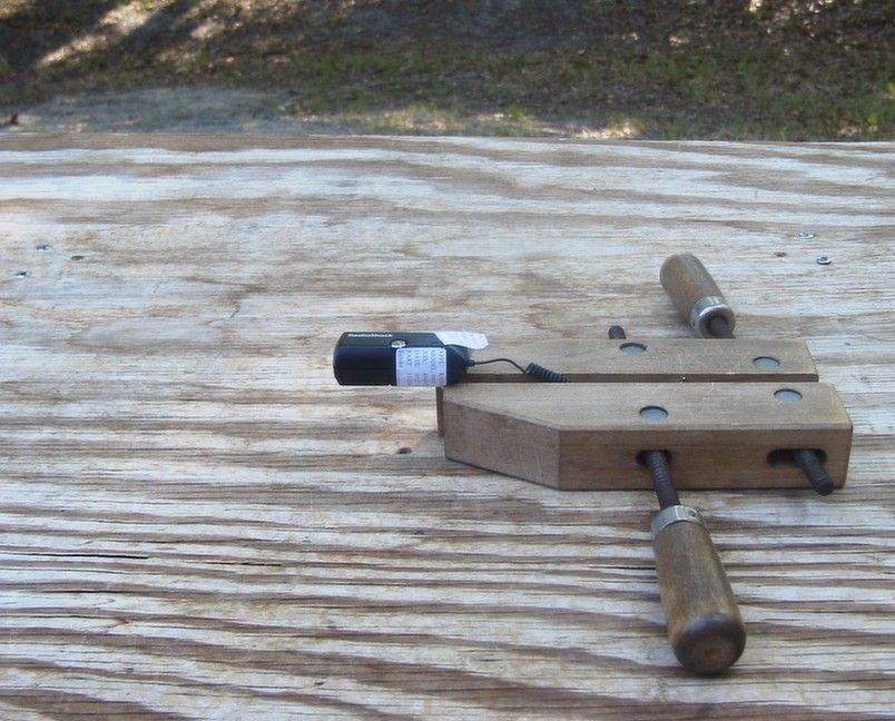
Document Text
Text extracted from the exhibit documents filed with the FCC. Open a document above to read the original.
Users Manual
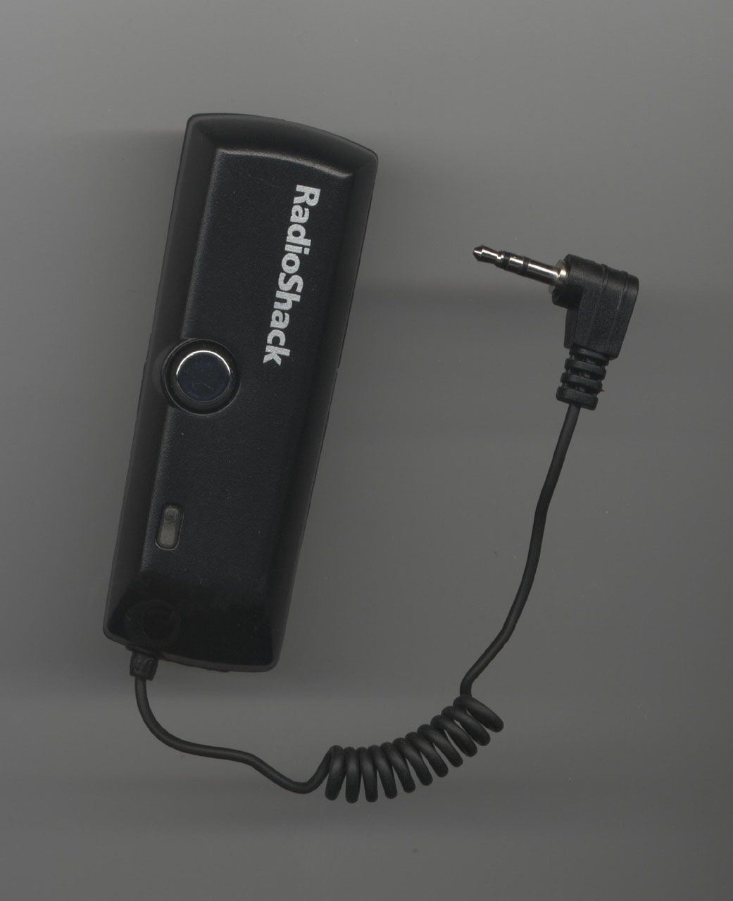
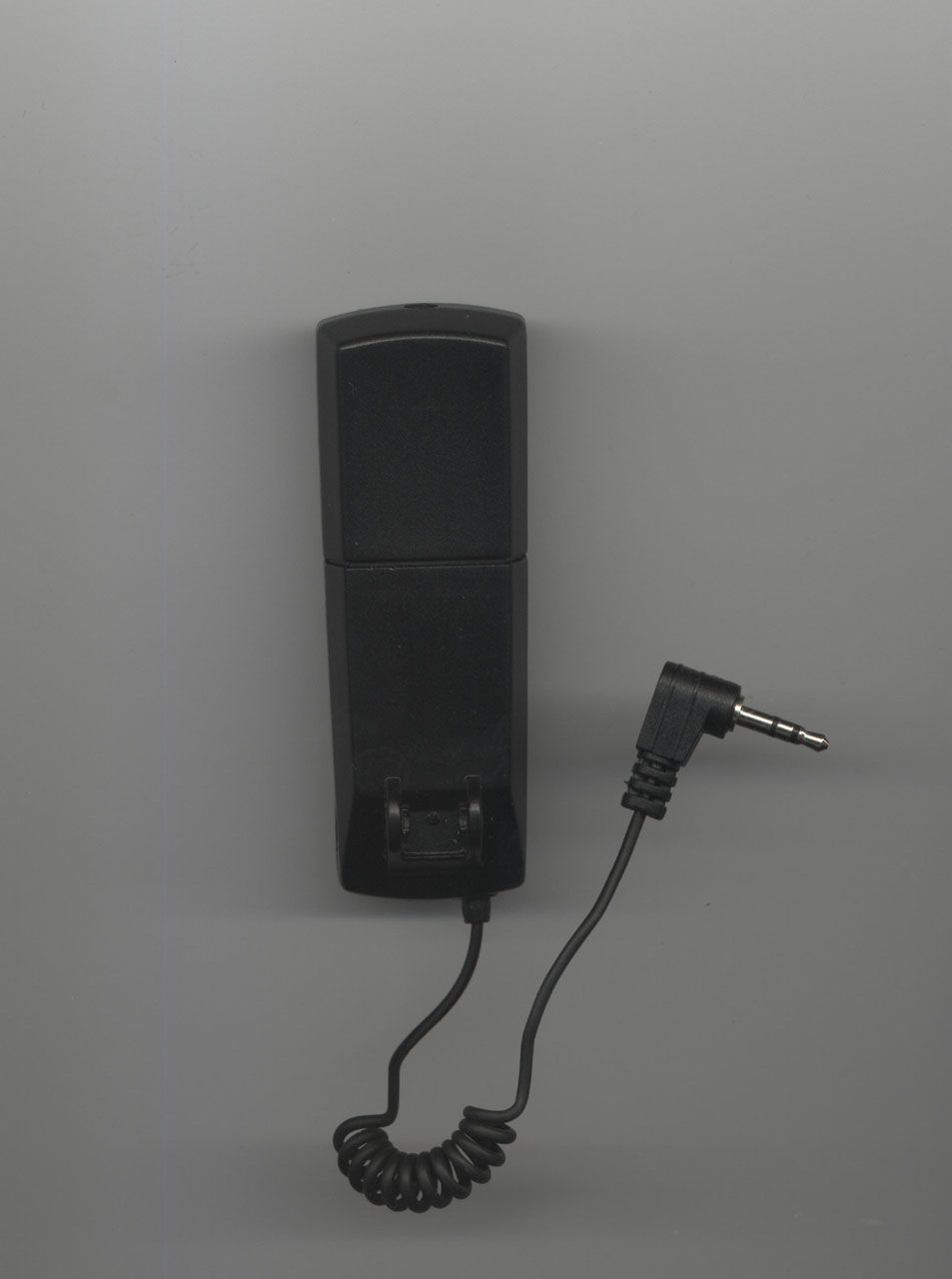
WARNING: 1. This device complies with Part 15 of the FCC Rules. Operation is subject to the following two conditions: • This device may not cause harmful interference, and • This device must accept any interference received, including interference that may cause undesired operation. 2. The Manufacturer is not responsible for any radio or TV interference caused by unauthorized modifications to this equipment. Such modifications could void the User’s authority to operate the equipment. _________________________________________________________________________________ 5 USER GUIDE PREPARATIONS • CHARGE THE HANDSFREE Plug the car adapter into the DC supply & connect the car adapter into DC jack of both Earset and Phoneset. Earset and Phoneset LED will flash once a second during charging. LED will flash twice a second upon charging completion. • CONNECT HANDSFREE TO PHONE Plug the 2.5mm audio plug of the Phoneset into audio jack of the phone. Different audio jack adapter may be required for different phone models. Check with your suppliers for adapter availability for your phone model. MODE OF OPERATION There are three operation modes for handsfree: • OFF MODE is a power down off mode. LED STATUS: Off. • STANDBY MODE is the operating mode readies for user to pick/drop a call. LED STATUS: Flashes. • TALK MODE means a link is established for user to talk over the handsfree system. LED STATUS: On. TURN ON/OFF THE HANDSFREE • TURN ON – Press the key over 6 second until LED flashes rapidly for 3 sec. Stop pressing when flash stops and LED will continue to flash once every second. • TURN OFF - Press the key over 6 second until LED flashes rapidly for 3 sec. Stop pressing when flash stops and the LED will stop flashing completely.. _________________________________________________________________________________ 6 PICK & DROP A CALL • Make sure that Phoneset and Earset is in turned on & within 20m distance. • TO PICK-UP A CALL press the Earset button once – line will be connected within at an average time of 1.5-sec (3 sec max). If connection fails, user will hear two beeps tone and need to reconnect the link again. • TO DROP A CALL, just press the earset button once further. OUT OF RANGE REMINDER • Earset generates a warning tone (1 beep per second for 15-sec) when distance between Earset & Phoneset exceed communication distance, approximately 20m. BATTERY-LOW REMINDER Earset will remind user of low battery by: • 4 beep & 4 LED flash every 5 seconds if Earset battery is low • 2 beep & 2 LED flash every 5 seconds if Phoneset battery is low • The Handsfree will terminate the communication link after 1-minute warning. No new calls will be allowed in low battery status before battery recharge. RESET Users can reset the earset or Phoneset by plugging the provided car cigarette charger into its DC socket if the unit does not work properly. ID CODE MATCHING _________________________________________________________________________________ 7 All pair is factory programmed and user IS NOT REQUIRED TO DO ANY ID CODE MATCHING. Users are suggested to use this mechanism only that Earset & Phoneset are from the different package. To program a Phoneset to work with another Earset, user shall: • Put the pair close to each other and press the button on both units continuously for 3 seconds. LEDs will be continuously fast flashing. • If the code matches successfully, LEDs will flash 4 times slowly and Earset will generate 4-beep tone. • If the code matches fails, the Earset will generate 2 beep-tone. PRECAUTIONS • Use ONLY provided car cigarette charger to charge the Handsfree. • DO NOT CHARGE both Units outside the temperature range of 0 to +45 degree Celsius. • DO NOT USE the both Units outside the temperature range of –5 to +50 degree Celsius. • DO NOT STORE the Units outside the allowable temperature range of –10 to +60 degree Celsius. • DO NOT TEMPER OR REMOVE THE LITHIUM ION BATTERIES • SHALL DISPOSE WITH EXTREME CARE. DISPOSE IN FIRE MAY HIGH POTENTIAL RISK OF EXPLOSION.
Operational Description
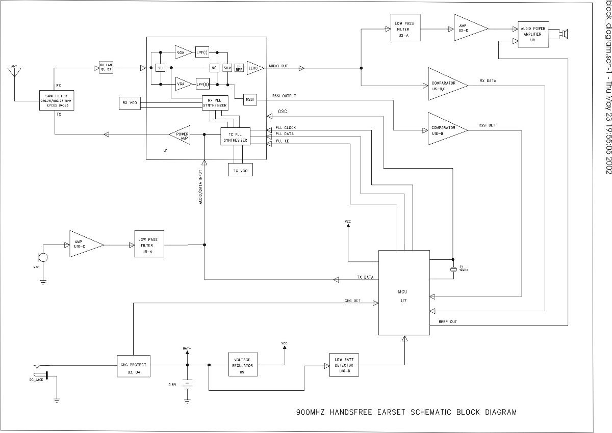
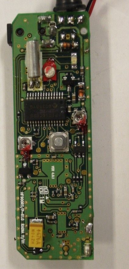
_________________________________________________________________________________ 3 THEORY OF OPERATION This part is to describe the operation theory of our handsfree device. Basically, our handsfree device can be divided into four sub-systems: 1) RF transceiver unit. 2) Baseband and digital control unit. 3) Audio unit. 4) Power management unit RF TRANSCEIVER UNIT This unit is used to convert the RF signal from/to the digital or audio signal at the baseband side. The RF unit is composed of a antenna, duplexer, LNA and a RADIA01 RFIC and to perform true full duplex operation. The duplexer in the RF unit is used to isolate the transmitting and receiving path to improve overall performance. • Incoming signal goes through duplexer that increase isolation from TX noise and get amplified by LNA before going through receiver section of Radia01 via a quadrature mixer in a direct-conversion, zero-intermediate frequency (zero-IF) approach. After quadrature down-conversion and baseband filtering, a quadrature mixer up-converts the complex baseband signal to an intermediate frequency (IF) for demodulation. There is no image frequencies as the IF is zero. • Radia01 transmitter section is comprised of a modulation-input circuit, a PLL synthesizer /VCO and a RF power amplifier providing a maximum of +3.0 dBm into a 50-Ohm load. It directly modulate the digital data or audio signal from the baseband part - such modulated signal will then be power amplified and transmitted through the duplexer and antenna. • The RFIC have also a built-in RSSI function (Receiving Signal Strength Indication) to indicate the existing noise level in order to achieve auto channel scanning and out-of-range detection features. • The existing antenna is a quarter wavelength AWG wire matched to the front end. _________________________________________________________________________________ 4 BASEBAND, AUDIO & DIGITAL CONTROL UNIT • This baseband and digital control unit is a central controller of the handsfree device. The audio circuit including microphone input amplifier and ID active filter and modulation input parts, receive audio filter amplifier, audio and ID code split circuit, and audio power amplifier circuit as well as a data slicer. • The main functions of the baseband and digital control unit include to control the operation mode and channel of the RFIC and all features of the handsfree device, such as ON/OFF control, out-of-range detection, battery-low alarm, etc.. are also controlled by this control unit. • MCU is also used as the data IN/OUT to the RFIC to make a connection between the Earset and Phoneset. • The audio unit is mainly used to amplify the audio from the mic. IN / to the speaker out for the earset and the audio IN/OUT from the mobile phone for phoneset. The audio unit can also provide the filter function to band limit the audio signal in order to improve the sound quality. POWER MANAGEMENT UNIT The power management unit comprises of 2 sub-systems: • 2 voltage regulating circuits supplying power to relevant RF block and rest of the device – these are controlled by the MCU for power conservation in different mode of operation i.e. Sleep Mode, Standby Mode & Active Mode; • A battery charging & discharging protection circuit as well as charging status indication.
Test Report
APPLICANT: AUTOMATIC MANUFACTURING LTD. FCC ID: JOZWHF430-P REPORT #: T:\A\Automatic_JOZ\717BHT2\717BHT2TestReport.doc TABLE OF CONTENTS LIST TABLE OF CONTENTS APPLICANT: AUTOMATIC MANUFACTURING LTD. FCC ID: JOZWHF430-P TEST REPORT CONTAINING: PAGE 1-5...........TEST EQUIPMENT LIST PAGE 6.............TEST PROCEDURE PAGE 7.............RADIATION INTERFERENCE TEST DATA PAGE 8.............OCCUPIED BANDWIDTH PAGE 9.............OCCUPIED BANDWIDTH PLOT PAGE 10............BANDEDGE CALCULATION PAGE 11............BANDEDGE PLOT PAGE 12............POWERLINE CONDUCTED PAGE 13-14.........POWERLINE CONDUCTED PLOTS EXHIBIT ATTACHMENTS: EXHIBIT 1...........FCC ID LABEL SAMPLE EXHIBIT 2...........SKETCH OF FCC ID LABEL LOCATION EXHIBIT 3...........BLOCK DIAGRAM EXHIBIT 4...........SCHEMATICS EXHIBIT 5...........INSTRUCTION MANUAL EXHIBIT 6...........OPERATIONAL DESCRIPTION EXHIBIT 7...........EXTERNAL FRONT VIEW EXHIBIT 8...........EXTERNAL REAR VIEW EXHIBIT 9...........COMPONENT SIDE INTERNAL PHOTOS EXHIBIT 10..........COPPER SIDE INTERNAL PHOTOS EXHIBIT 11..........TEST SET UP PHOTO APPLICANT: AUTOMATIC MANUFACTURING LTD. FCC ID: JOZWHF430-P REPORT #: T:\A\Automatic_JOZ\717BHT2\717BHT2TestReport.doc Page 1 of 14 Equipment List DEVICE MFGR MODEL SERNO CAL/CHAR DATE DUE DATE or STATUS X 3-Meter OATS TEI N/A N/A Listed 12/22/99 12/22/02 3/10-Meter OATS TEI N/A N/A Listed 3/26/01 3/26/04 X Receiver, Beige Tower X Spectrum Analyzer (Tan) HP 8566B Opt 462 3138A07786 3144A20661 CAL 8/31/01 8/31/02 X RF Preselector (Tan) HP 85685A 3221A01400 CAL 8/31/01 8/31/02 X Quasi-Peak Adapter (Tan) HP 85650A 3303A01690 CAL 8/31/01 8/31/02 Receiver, Blue Tower Spectrum Analyzer (Blue) HP 8568B 2928A04729 2848A18049 CHAR 10/22/01 10/22/02 RF Preselector (Blue) HP 85685A 2926A00983 CHAR 10/22/01 10/22/02 Quasi-Peak Adapter (Blue) HP 85650A 2811A01279 CHAR 10/22/01 10/22/02 Biconnical Antenna Electro-Metrics BIA-25 1171 CAL 4/26/01 4/26/03 X Biconnical Antenna Eaton 94455-1 1096 CAL 10/1/01 10/1/02 Biconnical Antenna Eaton 94455-1 1057 CHAR 3/15/00 3/15/01 BiconiLog Antenna EMCO 3143 9409-1043 X Log-Periodic Antenna Electro-Metrics LPA-25 1122 CAL 10/2/01 10/2/02 Log-Periodic Antenna Electro-Metrics EM-6950 632 CHAR 10/15/01 10/15/02 Log-Periodic Antenna Electro-Metrics LPA-30 409 CHAR 10/16/01 10/16/02 Dipole Antenna Kit Electro-Metrics TDA-30/1-4 152 CAL 3/21/01 3/21/02 APPLICANT: AUTOMATIC MANUFACTURING LTD. FCC ID: JOZWHF430-P REPORT #: T:\A\Automatic_JOZ\717BHT2\717BHT2TestReport.doc Page 2 of 14 Dipole Antenna Kit Electro-Metrics TDA-30/1-4 153 CHAR 11/24/00 11/24/01 Double-Ridged Horn Antenna Electro-Metrics RGA-180 2319 CAL 12/19/01 12/19/02 Horn Antenna Electro-Metrics EM-6961 6246 CAL 3/21/01 3/21/02 Horn Antenna ATM 19-443-6R None No Cal Required Passive Loop Antenna EMC Test Systems EMCO 6512 9706-1211 CHAR 7/10/01 7/10/02 Line Impedance Stabilization . . . Electro-Metrics ANS-25/2 2604 CAL 10/9/01 10/9/02 Line Impedance Stabilization . . . Electro-Metrics EM-7820 2682 CAL 3/16/01 3/16/02 Termaline Wattmeter Bird Electronic Corporation 611 16405 CAL 5/25/99 (5/25/00) Termaline Wattmeter Bird Electronic Corporation 6104 1926 CAL 12/12/01 12/12/02 Oscilloscope Tektronix 2230 300572 CHAR 2/1/01 2/1/02 Temperature Chamber Tenney Engineering TTRC 11717-7 CHAR 1/22/02 1/22/03 AC Voltmeter HP 400FL 2213A14499 CAL 10/9/01 10/9/02 AC Voltmeter HP 400FL 2213A14261 CHAR 10/15/01 10/15/02 AC Voltmeter HP 400FL 2213A14728 CHAR 10/15/01 10/15/02 Digital Multimeter Fluke 77 35053830 CHAR 1/8/02 1/8/03 Digital Multimeter Fluke 77 43850817 CHAR 1/8/02 1/8/03 Digital Multimeter HP E2377A 2927J05849 CHAR 1/8/02 1/8/03 Multimeter Fluke FLUKE-77-3 79510405 CAL 9/26/01 9/26/02 APPLICANT: AUTOMATIC MANUFACTURING LTD. FCC ID: JOZWHF430-P REPORT #: T:\A\Automatic_JOZ\717BHT2\717BHT2TestReport.doc Page 3 of 14 Peak Power Meter HP 8900C 2131A00545 CHAR 1/26/01 1/26/02 Digital Thermometer Fluke 2166A 42032 CAL 1/16/02 1/16/03 Thermometer Traulsen SK-128 CHAR 1/22/02 1/22/03 Temp/Humidity gauge EXTech 44577F E000901 CHAR 1/22/02 1/22/03 Frequency Counter HP 5352B 2632A00165 CAL 11/28/01 11/28/02 Power Sensor Agilent Technologies 84811A 2551A02705 CAL 1/26/01 1/26/02 Injection Probe Fischer Custom Communications F-120-9A 270 CAL 6/1/01 6/1/02 Service Monitor IFR FM/AM 500A 5182 CAL 11/22/00 11/22/01 Comm. Serv. Monitor IFR FM/AM 1200S 6593 CAL 11/12/99 11/12/00 Signal Generator HP 8640B 2308A21464 CAL 11/15/01 11/15/02 Modulation Analyzer HP 8901A 3435A06868 CAL 9/5/01 9/5/02 Power Line Coupling/ Decoupling Network Fischer Custom Communications FCC-801-M2- 16A 01048 CAL 8/29/01 8/29/02 Power Line Coupling/ Decoupling Network Fischer Custom Communications FCC-801-M3- 16A 01060 CAL 8/29/01 8/29/02 VHF/UHF Current Probe Fischer Custom Communications F-52 130 CAL 8/30/01 8/30/02 Passive Impedance Adapter Fischer Custom Communications FCC-801-150- 50-CDN 01117 & 01118 CAL 8/29/01 8/29/02 Radiating Field Coil Fischer Custom Communications F-1000-4- 8/9/10-L-1M 9859 CAL 10/15/98 10/15/99 Near Field Probe HP HP11940A 2650A02748 CHAR 2/1/01 2/1/02 APPLICANT: AUTOMATIC MANUFACTURING LTD. FCC ID: JOZWHF430-P REPORT #: T:\A\Automatic_JOZ\717BHT2\717BHT2TestReport.doc Page 4 of 14 BandReject Filter Lorch Microwave 5BR4-2400/ 60-N Z1 CHAR 3/2/01 3/2/02 BandReject Filter Lorch Microwave 6BR6-2442/ 300-N Z1 CHAR 3/2/01 3/2/02 BandReject Filter Lorch Microwave 5BR4-10525/ 900-S Z1 CHAR 3/2/01 3/2/02 High Pas Filter Microlab HA-10N CHAR 10/4/01 10/4/02 Audio Oscillator HP 653A 832-00260 CHAR 3/1/01 3/1/02 Frequency Counter HP 5382A 1620A03535 CHAR 3/2/01 3/2/02 Frequency Counter HP 5385A 3242A07460 CHAR 12/11/01 12/11/02 Preamplifier HP 8449B-H02 3008A00372 CHAR 3/4/01 3/4/02 Amplifier HP 11975A 2738A01969 CHAR 3/1/01 3/1/02 Egg Timer Unk CHAR 2/28/01 2/28/02 Measuring Tape, 20M Kraftixx 0631-20 CHAR 2/28/01 2/28/02 Measuring Tape, 7.5M Kraftixx 7.5M PROFI CHAR 2/28/01 2/28/02 EMC Immunity Test System Keytek CEMASTER 9810210 AC Power Source California Instrumen…
Text truncated - open the document above for the full version.
Contact Information
Applicant
Mok Kin Lun(Managing Director)
Test Firm
Timco Engineering, Inc.S Sanders
Technical Specifications
| # | Rule Parts | Frequency Range | Power Output |
|---|---|---|---|
| 1 | 15C | 925 MHz - 928 MHz | - |
Other Applications from Automatic Manufacturing Ltd

JOZWHF430-E
Aug 18, 2002Wireless Duplex Voice Transmitter
Equipment Class
DXX - Part 15 Low Power Communication Device TransmitterJOZAML-804RXA
Sep 14, 1993Wireless Doorbell Transmitter
Equipment Class
CRR - Superregenerative Receiver