JPZ0010Tabletop Light Dimmer
Lutron Electronics Company Inc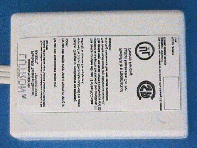
Click to zoom
Application Details
- Equipment Class
- DXT - Part 15 Low Power Transceiver, Rx Verified
- Date of Grant
- May 28, 2003
- Application Purpose
- Original Equipment
- Date of Application
- Apr 13, 1999
- Equipment Note
- Tabletop Light Dimmer
- Frequency Range
- 418.00000000 - 418.00000000
- Country
- United States
Documents & Files
Document Text
Text extracted from the exhibit documents filed with the FCC. Open a document above to read the original.
Block Diagram
FCC ID: JPZ0010 RAX-300TL Block Diagram
Cover Letter(s)
April 12, 1999 Federal Communications Commission Equipment Approval Services P.O. Box 358315 Pittsburgh, PA 15251-5315 Dear Sir / Madam, This submittal is in support of an Application for Certification in accordance with Part 2, Subpart J and Part 15, Subpart C of the Federal Communications Commission’s Rules and Regulations. The equipment is identified as the Lutron Tabletop Light Dimmer, RAX-300TL (FCC ID: JPZ0010). The submitted model number, RAX-300TL, is being used for brevity, and encompasses the following Lutron model numbers: RA-300TL RAS-300TL RALV-300TL Respectfully Submitted, Chris Rogan Design & Development Engineer
External Photos
FCC ID: JPZ0010 Top of RAX-300TL Bottom of RAX-300TL
ID Label/Location Info
FCC ID: JPZ0010 Proposed FCC ID Label
Internal Photos
FCC ID: JPZ0010 Internal Photographs Front side of PCB with Antenna Front side of PCB with Antenna removed FCC ID: JPZ0010 Internal Photographs Backside of PCB with Heat Sink Back side of PCB with Heat Sink removed
Test Report
FCC ID: JPZ0010 Average Factor Calculation ∴ 20dB Average Factor will be used.
Test Report
FCC ID: JPZ0010 i TABLE OF CONTENTS SECTIONTITLEPAGE Table of Contentsi List of Figuresi Administrative Dataii Summary of Test Resultsiii 1.0INDTRODUCTION1 2.0DESCRIPTION OF THE TEST SAMPLE2 3.0TEST INSTRUMENTATION3 4.0TEST RESULTS4 4.1Conducted Power Line Measurements4 4.2Radiated Emission Measurements5 5.0CONCLUSIONS9 APPENDIX ADATA SHEETS10-13 LIST OF FIGURES FIGURE 1 Conducted Test Setup Photograph6 2Radiated Test Setup Photograph7 3Photograph of Fundamental Frequency Bandwidth8 4Conducted Emission Data Sheet (Phase)11 5Conducted Emission Data Sheet (Neutral)12 6RE for Unintentional Radiators Data Sheet13 7RE for Intentional Radiators Data Sheet14 8Bandwidth of Fundamental Frequency Data Sheet15 FCC ID: JPZ0010 ii ADMINISTRATIVE DATA TEST PERFORMED: Measurements of radiated RF and conducted emissions.. PURPOSE OF TEST: To evaluate the ElectroMagnetic Emission (EME) characteristics of the Equipment Under Test with respect to Subpart B and C of Part 15 of the Federal Communications Commission (FCC) Rules for intentional and unintentional radiators. EQUIPMENT UNDER TEST (EUT): Model Number: RAX-300TL Unit Numbers: 18 and 21 CONTRACT: Purchase Order Number: NP-987661 TEST PERIOD: 01 April 1999 TEST FACILITY: Radiation Sciences Incorporated (RSI) , EMC Test Laboratory, located at: 651 North Cannon Avenue, Lansdale, PA 19446. TEST PERSONNEL AND COORDINATORS: Radiation Sciences Inc.Lutron Electronics Thomas KoesterRichard Black D. SignoreChris Rogan FCC ID: JPZ0010 iii SUMMARY OF TEST RESULTS The Model # RAX-300TL, configured as described herein, FULLY COMPLIES WITH THE REQUIREMENTS SET FORTH IN SUBPART B AND C OF PART 15 OF THE FEDERAL COMMUNICATIONS COMMISSION (FCC) RULES FOR INTENTIONAL AND UNINTENTIONAL RADIATORS. FCC ID: JPZ0010 1 1.0 INTRODUCTION This document is a report of tests to determine the EME characteristics of the Model # RAX- 300TL presented by Lutron Electronics of Coopersburg, Pennsylvania. The purpose of the testing was to evaluate the EMC characteristics of the test sample with respect to Subpart B and C of Part 15 of the FCC Rules for intentional and unintentional radiators. Test setups and procedures are described in RSI's Test Procedures 4963E (see Appendix B) and test results are summarized herein on graphs. All test procedures used meet the requirements of the American National Standards Institute Procedure C63.4: "Methods of Measurement of Radio-Noise Emissions from Low-Voltage Electrical and Electronic Equipment in the Range of 9kHz to 40GHz", dated 17 July 1992. FCC ID: JPZ0010 2 2.0 DESCRIPTION OF THE TEST SAMPLE: Device Function: The RAX-300TL is a table top mounted dimmer with attached power cord. The RAX-300TL contains a super-heterodyne receiver, a transmitter, and an antenna. It is used to control table lamps as part of an integrated lighting control system. The purpose of the RF communication is to transmit and receive command signals. Recieved command signals allow the RAX-300TL to turn ON or OFF in response to commands from the Lutron RAMC-XX master control keypads and the Lutron RA-REP. Transmitted command signals acknowledge the state of the RAX-300TL to the rest of the RadioRA system in response to manual button presses on a master control keypad. RF Function: The receiver down converts a 418MHz carrier frequency using a 407.3MHz local oscillator producing a 10.7MHz IF signal. The signal is further processed to decode data. The transmitter uses a SAW oscillator and power amplifier, which is keyed ON/OFF to produce the modulated carrier. Each RAX-300TL contains a micro controller running at 4MHz to ensure that all transmissions stop within 5 seconds of the button release or within 5 seconds on the beginning of the transmission or a transmission actuated automatically shall cease transmission within 5 seconds after activation. Modulation is AM, specifically ON/OFF Keyed (OOK) or sometimes called Amplitude Shift Keyed (ASK) data at 15.625kbps. The antenna cannot be modified or easily replaced by the user. Analog Function: The RAX-300TL derives power from the AC power line through the attached power cord. The device power supply and linear voltage regulator produce a 5V DC output which is used to power all analog and micro controller activities. FCC ID: JPZ0010 3 3.0 TEST INSTRUMENTATION C YT RSICALCY INVDUELP # DESCRIPTION MANUFACTURER MODEL # SERIAL # DATE E E 31SPEC ANALYZER ADVANTESTR3271J0035834/10/1999 12C 75ANTENNATENSOR41082041/6/200012C 80ANTENNAAMP.RES.Assoc. AT10004094-0251/6/200012C 91ANTENNAEMCO311520236/18/1999 6 V 245 LISNSOLAR8028-50-TS-24-BNC 8305255/18/1999 12C 260 LISN SOLAR8028-50-TS-24-BNC 97462912/21/1999 12C 390 RECEIVERRohde & Schwarz ESH 3861742/012 3/30/2000 12C 391 RECEIVERRohde & Schwarz ESVP 861744/015 3/30/2000 12C FCC ID: JPZ0010 4 4.0 TEST RESULTS 4.1 Conducted Power Line Measurements, Paragraphs § 15.107 Conducted power line measurements were recorded for the Model RAX-300TL. A test setup photograph is shown in Figure 1. The results of the line-to-ground radio noise voltage measurements are shown in Figures 4 and 5. Measurements were conducted on both the phase and neutral lines. ALL LEVELS ARE BELOW THE APPLICABLE LIMITS. FCC ID: JPZ0010 5 4.2 Radiated Emission Measurements, Paragraphs §15.33, §15.35, §15.109, §15.205, §15.209 and §15.231 See Figure 2 for a test setup photograph and Figure 3 for a photograph of the fundamental frequency bandwidth. Radiated emission measurements were recorded for the test sample at a distance of 3 meters, unless otherwise stated. The results of field strength measurements are illustrated on Figures 6 for unintentional radiators and Figures 7 and 8 for intentional radiators. Radiated emissions were measured with the antenna in both the horizontal and vertical polarizations. The antenna was raised 1 to 4 meters in height and the equipment under test (EUT) was rotated 360° to maximize the emission. For unintentional radiators, the emissions from the EUT were scanned from 30MHz to 2000MHz sin…
Text truncated - open the document above for the full version.
Test Report
FCC ID: JPZ0010 FCC ID: JPZ0010 FCC ID: JPZ0010 FIGURE1OATS EXTERIOR FIGURE 2OATS INTERIOR FCC ID: JPZ0010 FCC ID: JPZ0010 FCC ID: JPZ0010 FCC ID: JPZ0010 FCC ID: JPZ0010 FCC ID: JPZ0010 FCC ID: JPZ0010 FCC ID: JPZ0010 FCC ID: JPZ0010 FCC ID: JPZ0010 FCC ID: JPZ0010 FCC ID: JPZ0010
Test Report
FCC ID: JPZ0010 FCC ID: JPZ0010 FCC ID: JPZ0010 FCC ID: JPZ0010 FCC ID: JPZ0010 FCC ID: JPZ0010 FCC ID: JPZ0010 FCC ID: JPZ0010 FCC ID: JPZ0010
Contact Information
Applicant
Daniel Schlegel(Standards Compliance Supervisor)
Test Firm
Radiation Sciences IncorporatedDaniel Signore
215-256-4133Fax: 215-256-0775
Technical Specifications
| # | Rule Parts | Frequency Range | Power Output |
|---|---|---|---|
| 1 | 15C | 418 MHz - 418 MHz | - |
Other Applications from Lutron Electronics Company Inc
JPZ0161
Sep 03, 2026Wireless Interface
Equipment Class
DTS - Digital Transmission SystemJPZ0159
Aug 12, 2026Wireless Processor
Equipment Class
DTS - Digital Transmission SystemJPZ0158
Jul 27, 2026Copy of Wireless Processor
Equipment Class
DTS - Digital Transmission SystemJPZ0157
Mar 26, 2026LED Downlight
Equipment Class
DTS - Digital Transmission SystemJPZ0155
Sep 30, 2024LED Lighting Controller
Equipment Class
DTS - Digital Transmission System