JPZ0017Car Visor Control
Lutron Electronics Company Inc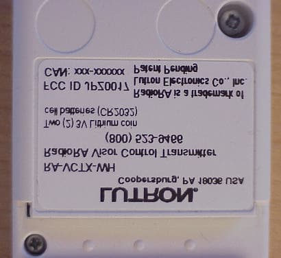
Click to zoom
Application Details
- Equipment Class
- DSC - Part 15 Security/Remote Control Transmitter
- Date of Grant
- Sep 20, 2001
- Application Purpose
- Original Equipment
- Date of Application
- Sep 20, 2001
- Equipment Note
- Car Visor Control
- Frequency Range
- 390.00000000 - 390.00000000
- Country
- United States
Documents & Files
Document Text
Text extracted from the exhibit documents filed with the FCC. Open a document above to read the original.
Users Manual
Preliminary RadioRA Car Visor Control Instructions 09/19/01 Page 1 of 10 Adding a Car Visor Control The Car Visor Control is a special type of Master Control. The System can have a maximum of 12 Master Controls. For every 1 Master Control NOT used, a Car Visor Control may be used in its place. NOTE: This equipment has been tested and found to comply with the limits for a Class B digital device, pursuant to Part 15 of the FCC Rules. These limits are designed to provide reasonable protection against harmful interference in a residential installation. This equipment generates, uses and can radiate radio frequency energy and, if not installed and used in accordance with the instructions, may cause harmful interference to radio communications. However, there is no guarantee that interference will not occur in a particular installation. If this equipment does cause harmful interference to radio or television reception, which can be determined by turning the equipment off and on, the user is encouraged to try to correct the interference by one or more of the following measures: Reorient or relocate the receiving antenna. Increase the separation between the equipment and receiver. Connect the equipment into an outlet on a circuit different from that to which the receiver is connected. Consult the dealer or an experienced radio/TV technician for help. CAUTION: Changes or modifications not expressly approved by Lutron Electronics could void the user’s authority to operate this equipment. Step 1 Begin Control Activation Press and hold the ACTIVATE CONTROLS button on any Repeater until the green ACTIVATE CONTROLS LED turns ON (approximately 3 seconds). Step 2 Activate Controls To add a Car Visor Control Press any button. • All LEDs will flash, then • Top and bottom row will flash alternately Middle row of LEDs will turn ON when the Master Control has been activated. Car Visor Receiver Step 3 Complete Car Visor Control Activation Press and hold the ACTIVATE CONTROLS button on any Repeater until the green ACTIVATE CONTROLS LED turns OFF (approximately 3 seconds). The green ACTIVATE CONTROLS LED on ALL Repeaters will turn OFF. The MAIN or AUXILIARY LED will remain on. Preliminary RadioRA Car Visor Instructions 09/19/01 Page 2 of 10 Programming Preparations Assigning the Lights Column of Buttons as ROOMS or SCENES on your Car Visor Control The right most column of buttons on a Car Visor Control can be programmed to be either ROOM or SCENE buttons. Step 1 Begin ROOM/SCENE Assignment Simultaneously press and hold the 3rd,5th, and ALL OFF buttons in the right most column until an LED in the right most column of the Car Visor Control which you are programming begins to flash (approximately 3 seconds). Step 2 Changing ROOM/SCENE Assignments Press the 1st button in a column to make that column a ROOM column, or press the 2nd button to make it a SCENE column. Step 3 Changing the closure type for the Input buttons Both CCI’s can be independently selected as Momentary or Maintained closures. Continued on next page. Preliminary RadioRA Car Visor Instructions 09/19/01 Page 3 of 10 Step 3 Changing the closure type for the Input buttons (continued) If a CCI is set as Momentary (default setting), its LED will be OFF. If a CCI is set as Maintained, its LEDs will be ON. To change the setting to Maintained, press and hold the CCI button until the LED turns ON. To change the setting to Momentary, press and hold the CCI button until the LED turns off. Step 4 Complete ROOM/SCENE Assignment Simultaneously press and hold the 3rd, 5th, and ALL OFF buttons in the right most column until the LEDs stop flashing (approximately 3 seconds). Step 5 Label columns Apply the supplied ROOMS or SCENES labels to the space provided over the right most button column. Preliminary RadioRA Car Visor Instructions 09/19/01 Page 4 of 10 Assigning Dimmers, Switches, or GRAFIK Eye Control Units to Car Visor Control Buttons Step 1 Begin assigning Dimmers, Switches, or GRAFIK Eye® Control Units to buttons Simultaneously press and hold the 2nd and 4th buttons in the right most column until the upper right LED begins to flash (approximately 3 seconds). Upper right LED flashes. Step 2 Select a Button Press the button that you want to program. Its LED will begin to flash. Valid Car Visor buttons that can to be programmed are the right most column buttons, ALL ON, ALL OFF, Inputs, or Security FULL and FLASH buttons. Preliminary RadioRA Car Visor Instructions 09/19/01 Page 5 of 10 Step 3 Assign a Dimmer, Switch, or GRAFIK Eye Control Unit to the button. Notes: • Multiple Dimmers, Switches, or GRAFIK Eye ® Control Units can be assigned to a button. • Controls must be assigned to a Car Visor Control button while its LED is flashing. Assign Dimmers or Switches to the Car Visor Control button by turning the Controls ON. Assign a GRAFIK Eye ® Control Unit to the Car Visor Control button by changing the selected GRAFIK Eye ® scene. If you assign the wrong Dimmer, Switch, or GRAFIK Eye ® Control Unit to the Car Visor Control button, turn the Dimmer, Switch, or GRAFIK Eye ® Control Unit OFF to unassign it. Note: GRAFIK Eye ® Control Units will automatically turn on to scene 1 once assigned. Step 4 Select a Button 2-3 until all buttons are programmed. When finished, proceed to Step 5. Step 5 Complete assigning Dimmers, Switches, or GRAFIK Eye® Control Units to buttons Simultaneously press and hold the 2nd and 4th buttons in the right most column until all LEDs begin to flutter (approximately 3 seconds). Preliminary RadioRA Car Visor Instructions 09/19/01 Page 6 of 10 Setting Light Levels/Grafik Eye Scene Selection for ROOM Buttons Setting Light Levels/ Levels/Grafik Eye Scene for SCENE Buttons This section is not complete yet... For this option, refer to the “Setting Light Levels” section of the RadioRA Setup Guide - Use Pages 1-11 and 1-12 for ROOM Buttons - Use Pages 1-15 and 1-16 for SCENE Buttons Preliminary RadioRA Car Visor Instructions 09/19/01 Page 7 of…
Text truncated - open the document above for the full version.
Block Diagram
Car Visor Block Diagram and Frequency Paths Overall System Block Diagram Transmitter Block Diagram
External Photos
Lutron – RadioRA Car Visor Transmitter Internal and External Photos Internal PCB Photo (Button Side) (Not real size) Internal PCB (Battery Side) (Not real size) External Transmitter (Top Button Side) (Not real size) External Transmitter (Bottom Side) (Not real size) External Transmitter – Zoom in on Labels (Not real size) (Not real size)
Internal Photos
Lutron – RadioRA Car Visor Transmitter Internal and External Photos Internal PCB Photo (Button Side) (Not real size) Internal PCB (Battery Side) (Not real size) External Transmitter (Top Button Side) (Not real size) External Transmitter (Bottom Side) (Not real size) External Transmitter – Zoom in on Labels (Not real size) (Not real size)
Test Report
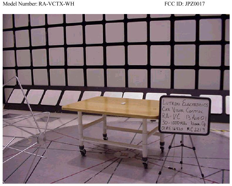
Page 1 of 20 Underwriters Laboratories Inc. 1285 Walt Whitman Rd. Melville, New York 11747 USA Tel.: 631 271-6200 Fax: 631 439-6095 Rev. No 1.0 Underwriters Laboratories Inc. 1285 Walt Whitman Road Melville, New York 11747-3081 (631) 271-6200 Report of Measurements of Electromagnetic Compatibility Testing Test Report File No.:MC2219Date of issue: 09/06/2001 Applicant:Lutron Electronics Co. Inc. Model / Serial No.:RA-VCTX-WH / Product Type:Car Visor Control Power Supply:2 - 3VDC lithium cell batteries Manufacturer:Same As Applicant License holder:Same As Applicant Address:7200 Suter Road :Coopersburg, PA 18036 Test Type: Compliance Investigation Manufacturer’s Specification Test Project Number:01ME16420 References(s)FCC ID: JPZ0017 Underwriters Laboratories Inc. authorizes the above-named company to reproduce this Report provided it is reproduced in its entirety. Underwriters Laboratories Inc. reports apply only to the specific samples tested under stated test conditions. It is the manufacturer's responsibility to assure that additional production units of this model are manufactured with identical electrical and mechanical components. Underwriters Laboratories Inc. shall have no liability for any deductions, inferences or generalizations drawn by the client or others from Underwriters Laboratories Inc. issued reports. This report is the confidential property of the client. As a mutual protection to our clients, the public and ourselves, extracts from the test report shall not be reproduced except in full without our written approval. This report shall not be used by the client to claim product endorsement by NVLAP or any agency of the US government. File Number: MC2219Issued: 09/06/2001 Project Number: 01ME16420 Model Number: RA-VCTX-WH FCC ID: JPZ0017 Page 2 of 20 Underwriters Laboratories Inc. 1285 Walt Whitman Rd. Melville, New York 11747 USA Tel.: 631 271-6200 Fax: 631 439-6095 Rev. No 1.0 Report Directory 1.0G E N E R A L - Product Description..........................................................................................3 1.1Device Configuration During Test......................................................................................................3 1.2Deviations from ANSI C63.4.............................................................................................................3 1.3Device Modifications Necessary for Compliance.................................................................................4 1.4Test Summary...................................................................................................................................4 1.5Immunity Performance Criteria..........................................................................................................5 2.0EMISSIONS TEST REGULATIONS.........................................................................................6 2.1EUT OPERATION MODE - EMISSIONS TESTS............................................................................6 2.1.1Radiated Emissions Test (10 Meter Semi-Anechoic Chamber)......................................................7 3.0SUMMARY:.................................................................................................................................20 File Number: MC2219Issued: 09/06/2001 Project Number: 01ME16420 Model Number: RA-VCTX-WH FCC ID: JPZ0017 Page 3 of 20 Underwriters Laboratories Inc. 1285 Walt Whitman Rd. Melville, New York 11747 USA Tel.: 631 271-6200 Fax: 631 439-6095 Rev. No 1.0 1.0 G E N E R A L - Product Description The EUT (equipment under test) is a device that intentionally transmits a Radio frequency (RF) communication to a receiver that control various devices manufactured by the customer. The device remains in a sleep mode until a switch is closed. When a switch is closed the circuit encodes a custom protocol to be repetitively sent out. The overall specification of the device is as follows: • 3 switch inputs for 7 possible functions • Baud rate is 2.5kbps – 86bit packets with 400us bit widths • Minimum of 4 transmitted packets per switch enclosure The antenna is not removable because it is an actual trace on the PCB. 1.1 Device Configuration During Test The device under test was modified by the manufacturer to continuously transmit data packets. The device operates on (2) 3VDC Lithium coin cell batteries The device was tested lying flat. This represents the worst-case orthogonal orientation. A new (fresh) battery was installed prior to each test. "The results contained in this report reflect the results for this particular model and serial number. It is the responsibility of the manufacturer to ensure that all production models meet the intent of the requirements detailed within this report" 1.2 Deviations from ANSI C63.4 Not Applicable As described below: File Number: MC2219Issued: 09/06/2001 Project Number: 01ME16420 Model Number: RA-VCTX-WH FCC ID: JPZ0017 Page 4 of 20 Underwriters Laboratories Inc. 1285 Walt Whitman Rd. Melville, New York 11747 USA Tel.: 631 271-6200 Fax: 631 439-6095 Rev. No 1.0 1.3 Device Modifications Necessary for Compliance N/A As described below: Resistor R18 was changed from 6.8ohms to 39ohms 1.4 Test Summary TestBasic Standard ConsideredTestedIn Compliance Conducted Voltage Emissions Discontinuous Interference (Click) Emissions Conducted Current Emissions Radiated EmissionsFCC Part 15 ̧ ̧ ̧ RFI Power Harmonic DistortionEN61000-3-2 Immunity to Voltage Fluctuations and Flicker EN51000-3-3 Magnetic Field Emissions Immunity to Electrostatic DischargeEN61000-4-2 Immunity to Continuous Radiated Disturbances EN61000-4-3 Immunity to Electrical Fast transientsEN61000-4-4 Immunity to SurgesEN61000-4-5 Immunity to Continuous Conducted Disturbances EN61000-4-6 Immunity to Power-Frequency Magnetic Fields EN61000-4-8 Immunity to Voltage Dips and Interruptions EN61000-4-11 File Number: MC2219Issued: 09/06/2001 Project Number: 01ME16420 Model Number: RA-VCTX-WH FCC ID: JPZ0017 Page 5 of 20 U…
Text truncated - open the document above for the full version.
Contact Information
Applicant
Daniel Schlegel(Standards Compliance Supervisor)
Technical Contact
Underwriters Laboratories Inc.James R Marley
[email protected](919) 549-1408
12 Laboratory Drive · Research Triangle Park, North Carolina · United States
Non-Technical Contact
Underwriters Laboratories Inc.James R Marley
[email protected](919) 549-1408
Test Firm
UL LLCBob Delisi
Technical Specifications
| # | Rule Parts | Frequency Range | Power Output |
|---|---|---|---|
| 1 | 15.231(e) | 390 MHz - 390 MHz | - |
Other Applications from Lutron Electronics Company Inc
JPZ0161
Sep 03, 2026Wireless Interface
Equipment Class
DTS - Digital Transmission SystemJPZ0159
Aug 12, 2026Wireless Processor
Equipment Class
DTS - Digital Transmission SystemJPZ0158
Jul 27, 2026Copy of Wireless Processor
Equipment Class
DTS - Digital Transmission SystemJPZ0157
Mar 26, 2026LED Downlight
Equipment Class
DTS - Digital Transmission SystemJPZ0155
Sep 30, 2024LED Lighting Controller
Equipment Class
DTS - Digital Transmission System