JPZ0021HRT-10KP
Lutron Electronics Company Inc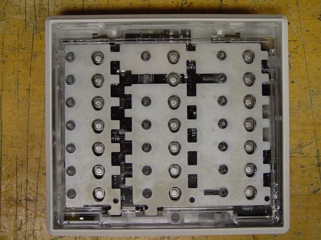
Click to zoom
Application Details
- Equipment Class
- DXT - Part 15 Low Power Transceiver, Rx Verified
- Date of Grant
- Nov 17, 2002
- Application Purpose
- Original Equipment
- Date of Application
- Nov 17, 2002
- Equipment Note
- HRT-10KP
- Frequency Range
- 431.00000000 - 437.00000000
- Country
- United States
Documents & Files
Document Text
Text extracted from the exhibit documents filed with the FCC. Open a document above to read the original.
Users Manual
1 Please Read Before Installing Installation Instructions Description The RF Tabletop Keypads are for use with HomeWorks Interactive systems. The keypad buttons are pro- grammed with a personal computer using the HomeWorks Interactive Programming Utility. Up to 32 keypads, each with a unique address, can be assigned to each HomeWorks Interactive RF Processor. HRT-5KP Important Notes Battery Models (-C only): Use only high quality alkaline batteries, two (2) size AAA, 1.5V. Caution - Do notuse rechargeable batteries. Using improperly rated batteries could damage the RF Tabletop Keypad. All Models (-A and -C): 1. Use only the DC adapter provided by Lutron with your Tabletop RF Keypad. Caution - Using a DC adapter not rated for the following specifications could damage the con- trol and possibly overheat the DC adapter. • Input: AC 120/127V, 50/60Hz • Output: DC 9V/300mA Class 2 2. Clean control with a soft damp cloth only. Do not use any chemical or abrasive cleaners. 3. Operate in ambient temperatures between 0°C (32°F) and 40°C (104°F). 4. Do not paint controls. 5. RF Keypads must be located within 30 feet (9m) of an RF Signal Repeater or an RF Processor. Multiple repeaters may be necessary to provide adequate coverage. 6.RF Keypads do not function until they are addressed and programmed. See the HomeWorks Interactive Programming Utility online help. HRT-5RL HRT-10KP HRT-10RL HRT-15KP HRT-15RL HRT-6LKP HRT-6LRL Tabletop Keypads HRT- 5KP-A, -C 10KP-A, -C 15KP-A, -C 6LKP-A, -C 5RL-A, -C 10RL-A, -C 15RL-A, -C 6LRL-A, -C 2 Battery Installation (-C Models) 1.Remove battery cover. 2.Install batteries as shown. Use two, 1.5V AAA Alkaline batteries only. 3. Replace battery cover. DC Adapter Installation (All Models) 1.Find a suitable location for the RF Tabletop Keypad.Place the Keypad in a convenient and accessible location. Note:RF Keypads should be located within 30 feet of an RF Signal Repeater or an RF Processor. 2. Apply power to the RF Tabletop Keypad. If the LEDs do not flash when powered, ensure that the DC adapter is installed properly and that there is power at the receptacle. If problem persists, call the Lutron Technical Support Center at (800) 523-9466. ? Optional Wall Mounting RF Tabletop Keypads may be wall mounted using the supplied wall bracket. Verify LEDs flash when pow- ered Plug in power cord and DC adapter Attach wall bracket to wall using the supplied screws and wall anchors. Wrap excess DC Adapter cord (if using) around the cord holder. Align Keypad and snap onto wall bracket. Note: (Battery-operated models only) • The RF Tabletop Keypad goes to “sleep” after a short period of inactivity. • Press any button to “wake up” the Keypad. 3 SymptomCause and Action • Keypad is not programmed into the system. See the RF Processor Instructions for setup details. • Keypad is out of system communications range. Move the keypad to within 30 feet of an RF Repeater or RF Processor. • Button being pressed has not been programmed. See the Programming Utility online help for programming details. • Dead, low, or no batteries in keypad. Replace the batter- ies. • Batteries are incorrectly installed. Install batteries as indi- cated inside the keypad. • Batteries are not making contact with the battery termi- nals. Adjust the batteries so they make contact with the terminals. • Batteries are low. Replace the batteries. • No power available to keypad. Plug in power supply. • Faulty power supply. Replace power supply. • Keypad is not programmed. See the RF Processor Instructions for setup details. After a Tabletop RF Keypad “wakes up”, additional button presses cause the control to flash all its LEDs simultane- ously. A Tabletop RF Keypad’s LEDs cycle up and down during “wake up”, but the system lights do not respond to button presses. A battery-operated Tabletop RF Keypad will not “wake up” when a button is pressed. A battery-operated Tabletop RF Keypad “wakes up” but goes to “sleep” quickly after a button press. Nothing happens when a Tabletop RF Keypad’s buttons are pressed. HomeWorks InteractiveTMKeypad Troubleshooting Keypad is working properly when LEDs light up and loads respond as buttons are pressed. RF Keypads do not function until they are addressed and programmed. See the HomeWorks Interactive Programming Utility online help. LIMITED WARRANTY Lutron will, at its option, repair or replace any unit that is defective in materials or manufac- ture within two years after purchase. After the two year period, a pro-rated warranty applies to this product until eight years after the purchase. For warranty service, return unit to place of purchase or mail to Lutron at 7200 Suter Rd., Coopersburg, PA 18036-1299, postage pre- paid. Telephone the Lutron Technical Support Center toll free at 800-523-9466. For more information regarding this warranty contact your Lutron representative. THIS WARRANTY IS IN LIEU OF ALL OTHER EXPRESS WARRANTIES, AND THE IMPLIED WARRANTY OF MERCHANTABILITY IS LIMITED TO TWO YEARS FROM PUR- CHASE. THIS WARRANTY DOES NOT COVER THE COST OF INSTALLATION, REMOVAL OR REINSTALLATION, OR DAMAGE RESULTING FROM MISUSE, ABUSE, OR IMPROPER OR INCORRECT REPAIR, OR DAMAGE FROM IMPROPER WIRING OR INSTALLATION. THIS WARRANTY DOES NOT COVER INCIDENTAL OR CONSEQUEN- TIAL DAMAGES. LUTRON’S LIABILITY ON ANY CLAIM FOR DAMAGES ARISING OUT OF OR IN CONNECTION WITH THE MANUFACTURE, SALE, INSTALLATION, DELIVERY, OR USE OF THE UNIT SHALL NEVER EXCEED THE PURCHASE PRICE OF THE UNIT. This warranty gives you specific legal rights, and you may also have other rights which vary from state to state. Some states do not allow limitations on how long an implied warranty lasts, so the above limitation may not apply to you. Some states do not allow the exclusion or limi- tation of incidental or consequential damages, so the above limitation or exclusion may not apply to you.This product may be covered by one or more of the following U.S. patents: 5,248,919; 5,736,965; 5,838,226; 5,905,442; D389,461; D39…
Text truncated - open the document above for the full version.
Users Manual
1 Please Read Before Installing Installation Instructions Description The RF Tabletop Keypads are for use with HomeWorks Interactive systems. The keypad buttons are pro- grammed with a personal computer using the HomeWorks Interactive Programming Utility. Up to 32 keypads, each with a unique address, can be assigned to each HomeWorks Interactive RF Processor. HRT-5KP Important Notes Battery Models (-C only): Use only high quality alkaline batteries, two (2) size AAA, 1.5V. Caution - Do notuse rechargeable batteries. Using improperly rated batteries could damage the RF Tabletop Keypad. All Models (-A and -C): 1. Use only the DC adapter provided by Lutron with your Tabletop RF Keypad. Caution - Using a DC adapter not rated for the following specifications could damage the con- trol and possibly overheat the DC adapter. • Input: AC 120/127V, 50/60Hz • Output: DC 9V/300mA Class 2 2. Clean control with a soft damp cloth only. Do not use any chemical or abrasive cleaners. 3. Operate in ambient temperatures between 0°C (32°F) and 40°C (104°F). 4. Do not paint controls. 5. RF Keypads must be located within 30 feet (9m) of an RF Signal Repeater or an RF Processor. Multiple repeaters may be necessary to provide adequate coverage. 6.RF Keypads do not function until they are addressed and programmed. See the HomeWorks Interactive Programming Utility online help. HRT-5RL HRT-10KP HRT-10RL HRT-15KP HRT-15RL HRT-6LKP HRT-6LRL Tabletop Keypads HRT- 5KP-A, -C 10KP-A, -C 15KP-A, -C 6LKP-A, -C 5RL-A, -C 10RL-A, -C 15RL-A, -C 6LRL-A, -C 2 Battery Installation (-C Models) 1.Remove battery cover. 2.Install batteries as shown. Use two, 1.5V AAA Alkaline batteries only. 3. Replace battery cover. DC Adapter Installation (All Models) 1.Find a suitable location for the RF Tabletop Keypad.Place the Keypad in a convenient and accessible location. Note:RF Keypads should be located within 30 feet of an RF Signal Repeater or an RF Processor. 2. Apply power to the RF Tabletop Keypad. If the LEDs do not flash when powered, ensure that the DC adapter is installed properly and that there is power at the receptacle. If problem persists, call the Lutron Technical Support Center at (800) 523-9466. ? Optional Wall Mounting RF Tabletop Keypads may be wall mounted using the supplied wall bracket. Verify LEDs flash when pow- ered Plug in power cord and DC adapter Attach wall bracket to wall using the supplied screws and wall anchors. Wrap excess DC Adapter cord (if using) around the cord holder. Align Keypad and snap onto wall bracket. Note: (Battery-operated models only) • The RF Tabletop Keypad goes to “sleep” after a short period of inactivity. • Press any button to “wake up” the Keypad. 3 SymptomCause and Action • Keypad is not programmed into the system. See the RF Processor Instructions for setup details. • Keypad is out of system communications range. Move the keypad to within 30 feet of an RF Repeater or RF Processor. • Button being pressed has not been programmed. See the Programming Utility online help for programming details. • Dead, low, or no batteries in keypad. Replace the batter- ies. • Batteries are incorrectly installed. Install batteries as indi- cated inside the keypad. • Batteries are not making contact with the battery termi- nals. Adjust the batteries so they make contact with the terminals. • Batteries are low. Replace the batteries. • No power available to keypad. Plug in power supply. • Faulty power supply. Replace power supply. • Keypad is not programmed. See the RF Processor Instructions for setup details. After a Tabletop RF Keypad “wakes up”, additional button presses cause the control to flash all its LEDs simultane- ously. A Tabletop RF Keypad’s LEDs cycle up and down during “wake up”, but the system lights do not respond to button presses. A battery-operated Tabletop RF Keypad will not “wake up” when a button is pressed. A battery-operated Tabletop RF Keypad “wakes up” but goes to “sleep” quickly after a button press. Nothing happens when a Tabletop RF Keypad’s buttons are pressed. HomeWorks InteractiveTMKeypad Troubleshooting Keypad is working properly when LEDs light up and loads respond as buttons are pressed. RF Keypads do not function until they are addressed and programmed. See the HomeWorks Interactive Programming Utility online help. LIMITED WARRANTY Lutron will, at its option, repair or replace any unit that is defective in materials or manufac- ture within two years after purchase. After the two year period, a pro-rated warranty applies to this product until eight years after the purchase. For warranty service, return unit to place of purchase or mail to Lutron at 7200 Suter Rd., Coopersburg, PA 18036-1299, postage pre- paid. Telephone the Lutron Technical Support Center toll free at 800-523-9466. For more information regarding this warranty contact your Lutron representative. THIS WARRANTY IS IN LIEU OF ALL OTHER EXPRESS WARRANTIES, AND THE IMPLIED WARRANTY OF MERCHANTABILITY IS LIMITED TO TWO YEARS FROM PUR- CHASE. THIS WARRANTY DOES NOT COVER THE COST OF INSTALLATION, REMOVAL OR REINSTALLATION, OR DAMAGE RESULTING FROM MISUSE, ABUSE, OR IMPROPER OR INCORRECT REPAIR, OR DAMAGE FROM IMPROPER WIRING OR INSTALLATION. THIS WARRANTY DOES NOT COVER INCIDENTAL OR CONSEQUEN- TIAL DAMAGES. LUTRON’S LIABILITY ON ANY CLAIM FOR DAMAGES ARISING OUT OF OR IN CONNECTION WITH THE MANUFACTURE, SALE, INSTALLATION, DELIVERY, OR USE OF THE UNIT SHALL NEVER EXCEED THE PURCHASE PRICE OF THE UNIT. This warranty gives you specific legal rights, and you may also have other rights which vary from state to state. Some states do not allow limitations on how long an implied warranty lasts, so the above limitation may not apply to you. Some states do not allow the exclusion or limi- tation of incidental or consequential damages, so the above limitation or exclusion may not apply to you.This product may be covered by one or more of the following U.S. patents: 5,248,919; 5,736,965; 5,838,226; 5,905,442; D389,461; D39…
Text truncated - open the document above for the full version.
External Photos
1 External Photos (top view) FCC ID: JPZ0021 HRT-10KP 2 External Photos (bottom view) FCC ID: JPZ0021 HRT-10KP 3 External Photos (antenna) FCC ID: JPZ0021 HRT-10KP
ID Label/Location Info
Proposed Unit Label (with JPZ number) FCC ID: JPZ0021 HRT-10KP Proposed location of unit label (left side view) FCC ID: JPZ0021 HRT-10KP Proposed FCC Warning Label FCC ID: JPZ0021 HRD-10KP
Internal Photos
1 Internal Photos (PCB top side) FCC ID: JPZ0021 HRT-10KP 2 Internal Photos (PCB bottom side) FCC ID: JPZ0021 HRT-10KP
Test Report
Underwriters Laboratories Inc. 1285 Walt Whitman Road Melville, New York 11747-3081 (631) 271-6200 Report of Measurements of Electromagnetic Compatibility Testing Test Report File No.: NC2219 Date of issue: 11/5/02 Applicant: Lutron Electronics Co. Inc. Model: HRT-10KP Product Type: Wireless Tabletop Keypad Power Supply: 120Vac, 60Hz Manufacturer: Same As Applicant License holder: Same As Applicant Address: 7200 Sutron Road Coopersburg, PA 18036 Test Type: ⌧ Compliance Investigation Manufacturer’s Specification Test Project Number: 02ME20017 References(s) FCC ID: JPZ0021 Underwriters Laboratories Inc. authorizes the above-named company to reproduce this Report provided it is reproduced in its entirety. Underwriters Laboratories Inc. reports apply only to the specific samples tested under stated test conditions. It is the manufacturer's responsibility to assure that additional production units of this model are manufactured with identical electrical and mechanical components. Underwriters Laboratories Inc. shall have no liability for any deductions, inferences or generalizations drawn by the client or others from Underwriters Laboratories Inc. issued reports. This report is the confidential property of the client. As a mutual protection to our clients, the public and ourselves, extracts from the test report shall not be reproduced except in full without our written approval. This report shall not be used by the client to claim product endorsement by NVLAP or any agency of the US government. Page 1 of 53 Underwriters Laboratories Inc. 1285 Walt Whitman Rd. Melville, New York 11747 USA Tel.: 631 271-6200 Fax: 631 439-6095 Rev. No 1.0 File Number: NC2219 Issued: 11/5/02 Project Number: 02ME20017 Model Number: HRT-10KP FCC ID: JPZ0021 Report Directory 1.0 G E N E R A L - Product Description.........................................................................................3 1.1 Device Configuration During Test............................................................................................................4 1.2 Deviations from ANSI C63.4....................................................................................................................4 1.3 Device Modifications Necessary for Compliance..................................................................................... 5 1.4 Test Summary............................................................................................................................................5 2.0 EMISSIONS TEST REGULATIONS........................................................................................6 2.1 EUT OPERATION MODE - EMISSIONS TESTS..................................................................................6 2.1.1 Conducted Emissions Tests................................................................................................................7 2.1.2 Cease Operation Within 5 Seconds.................................................................................................. 13 2.1.3 Radiated Emissions Test (10 Meter Semi-Anechoic Chamber).......................................................16 2.1.4 Occupied Bandwidth........................................................................................................................48 2.1.5 Fundamental Frequency and Spurious Emissions Measurement Limit Calculations.....................52 3.0 SUMMARY:...............................................................................................................................53 Page 2 of 53 Underwriters Laboratories Inc. 1285 Walt Whitman Rd. Melville, New York 11747 USA Tel.: 631 271-6200 Fax: 631 439-6095 Rev. No 1.0 File Number: NC2219 Issued: 11/5/02 Project Number: 02ME20017 Model Number: HRT-10KP FCC ID: JPZ0021 1.0 G E N E R A L - Product Description Device Function: The HRT-10KP is a tabletop keypad. It contains a FM transceiver and an antenna. It is used as part of an integrated lighting control system. The purpose of the RF communication is to transmit and receive command signals. Transmitted commands allow the triggering of system events. Received commands allow for updating of control indicator status. RF Function: The receiver down converts a 431-437MHz-carrier frequency using a 420.3-426.3MHz voltage-controlled oscillator producing a 10.7MHz IF signal. The signal is further processed to decode data. The transmitter uses the voltage-controlled oscillator, which is frequency modulated, and power amplifier to produce the modulated carrier. The HRT-10KP contains a micro controller running at 32MHz to ensure that all transmissions stop within 5 seconds of a button release or within 5 seconds on the beginning of a transmission. A transmission shall automatically cease within 5 seconds after activation. The ceasing of the transmission is accomplished via the micro controller. Modulation is FM, sometimes referred to as Frequency Shift Keyed (FSK), data at 62.5kbps. The antenna is permanently attached and cannot be modified or easily replaced by the user since it is underneath the plastic enclosure. The unit label permanently seals the plastic enclosure and snap features in the plastic. Analog Function: The HRT-10KP obtains power through a 120Vac to 9Vdc Class 2 transformer. The voltage is then linearly regulated down to a 5Vdc output, which is used to power all analog and micro controller activities. Page 3 of 53 Underwriters Laboratories Inc. 1285 Walt Whitman Rd. Melville, New York 11747 USA Tel.: 631 271-6200 Fax: 631 439-6095 Rev. No 1.0 File Number: NC2219 Issued: 11/5/02 Project Number: 02ME20017 Model Number: HRT-10KP FCC ID: JPZ0021 1.1 Device Configuration During Test The device under test was tested in normal orientation that represents the worst-case orientation. The device was tested in two modes of operation: 1. Continuously transmitting an intentional radio frequency in Continuous Wave (CW). 2. Standby mode (Receive). The device is waiting to receive a signal source. The …
Text truncated - open the document above for the full version.
Test Setup Photos
File Number: NC2219 Issued: 11/5/02 Project Number: 02ME20017 Model Number: HRT-10KP FCC ID: JPZ0021 Conducted Emission Test Set-Up 0.150 to 30MHz Page 12 of 53 Underwriters Laboratories Inc. 1285 Walt Whitman Rd. Melville, New York 11747 USA Tel.: 631 271-6200 Fax: 631 439-6095 Rev. No 1.0 File Number: NC2219 Issued: 11/5/02 Project Number: 02ME20017 Model Number: HRT-10KP FCC ID: JPZ0021 HRT-10 KP < 5 Seconds (total activation time 37.042ms) Page 14 of 53 Underwriters Laboratories Inc. 1285 Walt Whitman Rd. Melville, New York 11747 USA Tel.: 631 271-6200 Fax: 631 439-6095 Rev. No 1.0 File Number: NC2219 Issued: 11/5/02 Project Number: 02ME20017 Model Number: HRT-10KP FCC ID: JPZ0021 Test Set-Up Cease Operation < 5 seconds Page 15 of 53 Underwriters Laboratories Inc. 1285 Walt Whitman Rd. Melville, New York 11747 USA Tel.: 631 271-6200 Fax: 631 439-6095 Rev. No 1.0 File Number: NC2219 Issued: 11/5/02 Project Number: 02ME20017 Model Number: HRT-10KP FCC ID: JPZ0021 Pulse Train Test Set-Up Page 42 of 53 Underwriters Laboratories Inc. 1285 Walt Whitman Rd. Melville, New York 11747 USA Tel.: 631 271-6200 Fax: 631 439-6095 Rev. No 1.0 File Number: NC2219 Issued: 11/5/02 Project Number: 02ME20017 Model Number: HRT-10KP FCC ID: JPZ0021 Radiated Emission Test Set-Up 30-1000MHz Front View Page 43 of 53 Underwriters Laboratories Inc. 1285 Walt Whitman Rd. Melville, New York 11747 USA Tel.: 631 271-6200 Fax: 631 439-6095 Rev. No 1.0 File Number: NC2219 Issued: 11/5/02 Project Number: 02ME20017 Model Number: HRT-10KP FCC ID: JPZ0021 Radiated Emission Test Set-Up 30-1000MHz Front View Page 44 of 53 Underwriters Laboratories Inc. 1285 Walt Whitman Rd. Melville, New York 11747 USA Tel.: 631 271-6200 Fax: 631 439-6095 Rev. No 1.0 File Number: NC2219 Issued: 11/5/02 Project Number: 02ME20017 Model Number: HRT-10KP FCC ID: JPZ0021 Radiated Emission Test Set-Up 30-1000MHz Front View Page 45 of 53 Underwriters Laboratories Inc. 1285 Walt Whitman Rd. Melville, New York 11747 USA Tel.: 631 271-6200 Fax: 631 439-6095 Rev. No 1.0 File Number: NC2219 Issued: 11/5/02 Project Number: 02ME20017 Model Number: HRT-10KP FCC ID: JPZ0021 Radiated Emission Test Set-Up 1 to 2GHz Page 46 of 53 Underwriters Laboratories Inc. 1285 Walt Whitman Rd. Melville, New York 11747 USA Tel.: 631 271-6200 Fax: 631 439-6095 Rev. No 1.0 File Number: NC2219 Issued: 11/5/02 Project Number: 02ME20017 Model Number: HRT-10KP FCC ID: JPZ0021 Radiated Emission Test Set-Up 1 to 5GHz Page 47 of 53 Underwriters Laboratories Inc. 1285 Walt Whitman Rd. Melville, New York 11747 USA Tel.: 631 271-6200 Fax: 631 439-6095 Rev. No 1.0 File Number: NC2219 Issued: 11/5/02 Project Number: 02ME20017 Model Number: HRT-10KP FCC ID: JPZ0021 Occupied Bandwidth Test Set-Up HRT-10KP Page 51 of 53 Underwriters Laboratories Inc. 1285 Walt Whitman Rd. Melville, New York 11747 USA Tel.: 631 271-6200 Fax: 631 439-6095 Rev. No 1.0
Test Setup Photos
File Number: NC2219 Issued: 11/5/02 Project Number: 02ME20017 Model Number: HRT-10KP FCC ID: JPZ0021 Conducted Emission Test Set-Up 0.150 to 30MHz Page 12 of 53 Underwriters Laboratories Inc. 1285 Walt Whitman Rd. Melville, New York 11747 USA Tel.: 631 271-6200 Fax: 631 439-6095 Rev. No 1.0 File Number: NC2219 Issued: 11/5/02 Project Number: 02ME20017 Model Number: HRT-10KP FCC ID: JPZ0021 HRT-10 KP < 5 Seconds (total activation time 37.042ms) Page 14 of 53 Underwriters Laboratories Inc. 1285 Walt Whitman Rd. Melville, New York 11747 USA Tel.: 631 271-6200 Fax: 631 439-6095 Rev. No 1.0 File Number: NC2219 Issued: 11/5/02 Project Number: 02ME20017 Model Number: HRT-10KP FCC ID: JPZ0021 Test Set-Up Cease Operation < 5 seconds Page 15 of 53 Underwriters Laboratories Inc. 1285 Walt Whitman Rd. Melville, New York 11747 USA Tel.: 631 271-6200 Fax: 631 439-6095 Rev. No 1.0 File Number: NC2219 Issued: 11/5/02 Project Number: 02ME20017 Model Number: HRT-10KP FCC ID: JPZ0021 Pulse Train Test Set-Up Page 42 of 53 Underwriters Laboratories Inc. 1285 Walt Whitman Rd. Melville, New York 11747 USA Tel.: 631 271-6200 Fax: 631 439-6095 Rev. No 1.0 File Number: NC2219 Issued: 11/5/02 Project Number: 02ME20017 Model Number: HRT-10KP FCC ID: JPZ0021 Radiated Emission Test Set-Up 30-1000MHz Front View Page 43 of 53 Underwriters Laboratories Inc. 1285 Walt Whitman Rd. Melville, New York 11747 USA Tel.: 631 271-6200 Fax: 631 439-6095 Rev. No 1.0 File Number: NC2219 Issued: 11/5/02 Project Number: 02ME20017 Model Number: HRT-10KP FCC ID: JPZ0021 Radiated Emission Test Set-Up 30-1000MHz Front View Page 44 of 53 Underwriters Laboratories Inc. 1285 Walt Whitman Rd. Melville, New York 11747 USA Tel.: 631 271-6200 Fax: 631 439-6095 Rev. No 1.0 File Number: NC2219 Issued: 11/5/02 Project Number: 02ME20017 Model Number: HRT-10KP FCC ID: JPZ0021 Radiated Emission Test Set-Up 30-1000MHz Front View Page 45 of 53 Underwriters Laboratories Inc. 1285 Walt Whitman Rd. Melville, New York 11747 USA Tel.: 631 271-6200 Fax: 631 439-6095 Rev. No 1.0 File Number: NC2219 Issued: 11/5/02 Project Number: 02ME20017 Model Number: HRT-10KP FCC ID: JPZ0021 Radiated Emission Test Set-Up 1 to 2GHz Page 46 of 53 Underwriters Laboratories Inc. 1285 Walt Whitman Rd. Melville, New York 11747 USA Tel.: 631 271-6200 Fax: 631 439-6095 Rev. No 1.0 File Number: NC2219 Issued: 11/5/02 Project Number: 02ME20017 Model Number: HRT-10KP FCC ID: JPZ0021 Radiated Emission Test Set-Up 1 to 5GHz Page 47 of 53 Underwriters Laboratories Inc. 1285 Walt Whitman Rd. Melville, New York 11747 USA Tel.: 631 271-6200 Fax: 631 439-6095 Rev. No 1.0 File Number: NC2219 Issued: 11/5/02 Project Number: 02ME20017 Model Number: HRT-10KP FCC ID: JPZ0021 Occupied Bandwidth Test Set-Up HRT-10KP Page 51 of 53 Underwriters Laboratories Inc. 1285 Walt Whitman Rd. Melville, New York 11747 USA Tel.: 631 271-6200 Fax: 631 439-6095 Rev. No 1.0
Contact Information
Applicant
Daniel Schlegel(Standards Compliance Supervisor)
Technical Contact
LUTRON ELECTRONICS INCROBERT BOLLINGER
[email protected]610-282-6457
7200 SUTER ROAD · COOPERSBURG, Pennsylvania · United States
Non-Technical Contact
LUTRON ELECTRONICS INCROBERT SPEHALSKI
[email protected]610-282-7424
Test Firm
UL LLCBob Delisi
Technical Specifications
| # | Rule Parts | Frequency Range | Power Output |
|---|---|---|---|
| 1 | 15C | 431 MHz - 437 MHz | - |
Other Applications from Lutron Electronics Company Inc
JPZ0161
Sep 03, 2026Wireless Interface
Equipment Class
DTS - Digital Transmission SystemJPZ0159
Aug 12, 2026Wireless Processor
Equipment Class
DTS - Digital Transmission SystemJPZ0158
Jul 27, 2026Copy of Wireless Processor
Equipment Class
DTS - Digital Transmission SystemJPZ0157
Mar 26, 2026LED Downlight
Equipment Class
DTS - Digital Transmission SystemJPZ0155
Sep 30, 2024LED Lighting Controller
Equipment Class
DTS - Digital Transmission System