JPZ0025STRD-7B Transceiver (Keypad)
Lutron Electronics Company Inc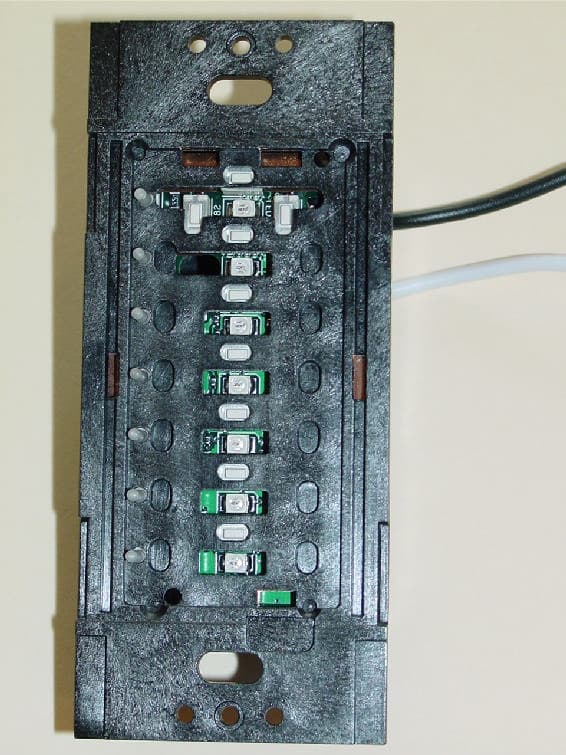
Click to zoom
Application Details
- Equipment Class
- DSR - Part 15 Remote Control/Security Device Transceiver
- Date of Grant
- Jul 21, 2003
- Application Purpose
- Original Equipment
- Date of Application
- Jul 21, 2003
- Equipment Note
- STRD-7B Transceiver (Keypad)
- Frequency Range
- 431.00000000 - 437.00000000
- Country
- United States
Documents & Files
Document Text
Text extracted from the exhibit documents filed with the FCC. Open a document above to read the original.
Users Manual
LEDs don't light up when buttons arepressed.Button presses on keypad cause the key-pad to quickly flash all its LEDs simultane- ously.Button presses on keypad cause the key-pad to slowly flash all its LEDs simultane- ously.Keypad cannot be addressed.LEDs light when button is pressed, but thesystem response is not correct. Designer-style RF seeTouch TM KeypadsSTRD-1B, -2B, -3B, -3BRL, -4B, -4FS, -4S,-4SIR, -5B, -5FS, -5BRL, -6B, -6BRL, -7B120 V ~, 50/60 Hz, 0.2 A Installation Instructions Please Read Before Installing Lutron Electronics Co., Inc. 7200 Suter RoadCoopersburg, PA 18036-1299Made and printed in the U.S.A. 02/03 P/N 043-146 Rev. A LIMITED WARRANTYLutron will, at its option, repair or replace any unit that is defective in materials or manufacture within two years after purchase. For warranty serv-ice, return unit to place of purchase or mail to Lutron at 7200 Suter Rd., Coopersburg, PA 18036-1299, postage pre-paid. Telephone the LutronTechnical Support Center toll free at 800-523-9466. After the two year period, a pro-rated warranty applies to this product until eight years afterthe purchase. For more information regarding this warranty contact your Lutron representative.THIS WARRANTY IS IN LIEU OF ALL OTHER EXPRESS WARRANTIES, AND THE IMPLIED WARRANTY OF MERCHANTABILITY IS LIM-ITED TO TWO YEARS FROM PURCHASE. THIS WARRANTY DOES NOT COVER THE COST OF INSTALLATION, REMOVAL OR REIN-STALLATION, OR DAMAGE RESULTING FROM MISUSE, ABUSE, OR IMPROPER OR INCORRECT REPAIR, OR DAMAGE FROM IMPROP-ER WIRING OR INSTALLATION. THIS WARRANTY DOES NOT COVER INCIDENTAL OR CONSEQUENTIAL DAMAGES. LUTRON’S LIA-BILITY ON ANY CLAIM FOR DAMAGES ARISING OUT OF OR IN CONNECTION WITH THE MANUFACTURE, SALE, INSTALLATION,DELIVERY, OR USE OF THE UNIT SHALL NEVER EXCEED THE PURCHASE PRICE OF THE UNIT.This warranty gives you specific legal rights, and you may also have other rights which vary from state to state. Some states do not allow limita-tions on how long an implied warranty lasts, so the above limitation may not apply to you. Some states do not allow the exclusion or limitation ofincidental or consequential damages, so the above limitation or exclusion may not apply to you.These products may be covered under one or more of the following U.S. patents: 4,835,343; 4,889,999; 5,170,068; 5,237,207; 5,73 6,965; 5,838,226; 5,848,054; 5,905,442; 5,982,103; D436,930; D453,742; D456,783; D461,782; D465,460; D465,770; D466,090; D466,091; D46 6,484 and corresponding foreign patents. U.S. and foreign patents pending. Lutron, Claro and HomeWorks are registered trademarks and Satin Colors, seeTouch and the HomeWorks Logo are trademarks of Lutron Electronics Co., Inc.© 2003 Lutron Electronics Co., Inc.Technical and Sales AssistanceIf you need assistance, call the toll-free Lutron Technical Support Center . Please provide exact model number when calling.(800) 523-9466 (U.S.A., Canada and the Caribbean)Other countries call:Tel: (610) 282-3800 Fax: (610) 282-3090Visit our Web site at www.lutron.com FCC InformationNote: This equipment has been tested and found to comply with the limits for a Class B digital device, pursuant to Part 15 of the FCC rules. These limits are designed to provide reasonable protection against harmful interference in a resi-dential installation. This equipment generates, uses and can radiate radio frequency energy and, if not installed inaccordance with the instructions, may cause harmful interference to radio communications. However, there is no guar-antee that interference will not occur in a particular installation. If this equipment does cause harmful interference toradio or television reception, which can be determined by turning the equipment off and on, the user is encouraged totry to correct the interference by one or more of the following measures: • Reorient or relocate the receiving antenna.• Increase the seperation between the equipment and receiver.• Connect the equipment into an outlet on a circuit different from that to which the receiver is connected.• Consult the dealer or an experienced radio/TV technician for help. Caution: Changes or modifications not expressly approved by Lutron Electronics Co. could void the user’s authority to operate this equipment. Overview The STRD-1B, -2B, -3B, -3BRL, -4B, -4FS, -4S, -4SIR,-5B, -5FS, -5BRL, -6B, -6BRL,and -7B keypads are for usewith HomeWorks systems. The keypad buttons are pro-grammed with a personalcomputer using theHomeWork s Utility. Up to 32 keypads, each with aunique address, can beassigned to each HomeWorks RF Processor. Important NotesCodes: Install in accordance with all local and national electri- cal codes.Environment: Ambient operating temperature: 0-40°C, 32-104°F, 0-90% humidity, non-condensing. Indoor useonly.Wallplates: Lutron Claro ® and Satin Colors TM wallplates are rec- ommended for best color match and clean aesthetic appear-ance. Do not paint controls or wallplates.Cleaning: To clean, wipe with a clean damp cloth. DO NOT use any chemical cleaning solutions.Wallboxes: Lutron recommends using 3-1/2 in. (89 mm) deep wallboxes for easier installation. RF Device Placement : RF Keypads must be located within 30 ft. (9 m) of an RF Signal Repeater or an RF Processor. RF Keypads will not function until they are addressed and pro-grammed using the HomeWorks Utility. STRD-4SIR* STRD-6BRL* STRD-7B* STRD-1B* STRD-2B* STRD-3B* STRD-3BRL* STRD-4B* STRD-4FS* STRD-5B* STRD-5FS* STRD-6B* STRD-4S*STRD-5BRL* * Wallplate/Adapterpurchased separately. 1. Turn power OFF at fusebox or circuit breaker. Danger - Locate and remove fuse or lock circuit breaker in the OFF position before proceeding. Wiring withpower ON may result in personal injury. 2. Prepare wires. When making wire connections, follow therecommended strip lengths and combinations for the sup-plied wire connectors. Note: Wire connectors provided aresuitable for copper wire only . Small: Strip insulation 3/8 in. (10 mm) for 14 AWG (2.5 mm 2 ). Strip insulation 1/2 in. (13 mm) for…
Text truncated - open the document above for the full version.
Attestation Statements
July 17, 2003 Underwriters Laboratories, Inc. 1285 Walt Whitman Road Melville, NY 11747-3081 Attn: Mr. Joe Danisi Subject: Request for Confidentiality – STRD-7B JPZ0025 Dear Joe, This letter is to formally request confidentiality per the FCC Rules 47 CFR Chapter 1, subpart C, section 0.459 - requests that materials or information submitted to the Commission be withheld from public inspection. For model STRD-7B, Wall Keypad Transceiver, the following items are Lutron Electronics Co., Inc. confidential information that must be withheld from public inspection by potential competitors to protect our business. 1. Schematics 2. Theory of operation Thank you for your cooperation. Sincerely, R. S. Spehalski Engineering Leader
External Photos
JPZ0025 Lutron project 487STRD-7B External Photos (front view with buttons) JPZ0025 Lutron project 487STRD-7B External Photos (front view without buttons) JPZ0025 Lutron project 487STRD-7B External Photos (rear view)
ID Label/Location Info
JPZ0025 Lutron project 487STRD-7B ID label/location info (FCC ID) JPZ0025 Lutron project 487STRD-7B ID label/location info (FCC part 15 label)
Internal Photos
JPZ0025 Lutron project 487STRD-7B Internal Photos (PCB front/top) JPZ0025 Lutron project 487STRD-7B Internal Photos (PCB bottom/rear) JPZ0025 Lutron project 487STRD-7B Internal Photos (antenna inside housing)
Test Report
Underwriters Laboratories Inc. 1285 Walt Whitman Road Melville, New York 11747-3081 (631) 271-6200 Report of Measurements Of Electromagnetic Compatibility Testing Test Report File No.: NC2219 Date of issue: 6/18/2003 Applicant: Lutron Electronics Co. Inc. Model: STRD-7B Product Type: Transceiver (431 to 437MHz) Power Supply: 120Vac, 60Hz Manufacturer: Same As Applicant License holder: Same As Applicant Address: 7200 Suter Road Coopersburg, PA 18036 Test Type: Compliance Investigation Test Project Number: 03ME09392 References(s) FCC ID: JPZ0025 Underwriters Laboratories Inc. authorizes the above-named company to reproduce this Report provided it is reproduced in its entirety. Underwriters Laboratories Inc. reports apply only to the specific samples tested under stated test conditions. It is the manufacturer's responsibility to assure that additional production units of this model are manufactured with identical electrical and mechanical components. Underwriters Laboratories Inc. shall have no liability for any deductions, inferences or generalizations drawn by the client or others from Underwriters Laboratories Inc. issued reports. This report is the confidential property of the client. As a mutual protection to our clients, the public and ourselves, extracts from the test report shall not be reproduced except in full without our written approval. The client to claim product endorsement by NVLAP or any agency of the US government shall not use this report. File Number: NC2219 Issued: 6/18/2003 Project Number: 03ME09392 Model Number: STRD-7B FCC ID: JPZ0025 Page 2 of 58 Underwriters Laboratories Inc. 1285 Walt Whitman Rd. Melville, New York 11747 USA Tel.: 631 271-6200 Fax: 631 439-6095 Rev. No 1.0 Report Directory 1.0 G E N E R A L - Product Description.......................................................................................... 3 1.1 Device Configuration During Test .............................................................................................................. 4 1.2 Deviations from ANSI C63.4 ...................................................................................................................... 5 1.3 Device Modifications Necessary for Compliance ....................................................................................... 5 1.4 Test Summary.............................................................................................................................................. 5 1.5 FCC Labeling Information .......................................................................................................................... 6 2.0 EMISSIONS TEST REGULATIONS ......................................................................................... 6 2.1 EUT OPERATION MODE - EMISSIONS TESTS .................................................................................... 6 2.1.2 Conducted Emissions ........................................................................................................................ 17 2.1.3 Cease Operation Within 5 Seconds...........................................................................10 2.1.4 Radiated Emissions Test (10 Meter Semi-Anechoic Chamber)........................................................ 20 2.1.5 Occupied Bandwidth ......................................................................................................................... 52 2.1.6 Fundamental Frequency and Spurious Emissions Measurement Limit Calculations ....................... 57 3 SUMMARY:....................................................................................................................................... 58 File Number: NC2219 Issued: 6/18/2003 Project Number: 03ME09392 Model Number: STRD-7B FCC ID: JPZ0025 Page 3 of 58 Underwriters Laboratories Inc. 1285 Walt Whitman Rd. Melville, New York 11747 USA Tel.: 631 271-6200 Fax: 631 439-6095 Rev. No 1.0 1.0 G E N E R A L - Product Description Device Function: The STR Keypad is a wall mounted master control station. It contains an FM transceiver and an antenna, which is not accessible to the user. It is used as part of an integrated lighting control system. The purpose of the RF communication is to transmit and receive command signals. Transmitted commands allow the triggering of system events. Received commands allow for updating of control indicator status. RF Function: The receiver down converts a 431-437MHz-carrier frequency using a 420.3-426.3MHz voltage-controlled oscillator producing a 10.7MHz IF signal. The signal is further processed to decode data. The transmitter uses the voltage-controlled oscillator, which is frequency modulated, and power amplifier to produce the modulated carrier. The STR Keypad contains a micro controller running at 32MHz to ensure that all transmissions stop within 5 seconds of a button release or within 5 seconds on the beginning of a transmission. A transmission shall automatically cease within 5 seconds after activation. The ceasing of the transmission is accomplished via the micro-controller. Modulation is FM, sometimes referred to as Frequency Shift Keyed (FSK), data at 62.5kbps. The antenna cannot be easily modified or replaced by the user. Analog Function: The STR Keypad obtains power through standard household wiring. The power supply and voltage regulator produces a 5Vdc output, which is used to power all analog and micro controller activities. File Number: NC2219 Issued: 6/18/2003 Project Number: 03ME09392 Model Number: STRD-7B FCC ID: JPZ0025 Page 4 of 58 Underwriters Laboratories Inc. 1285 Walt Whitman Rd. Melville, New York 11747 USA Tel.: 631 271-6200 Fax: 631 439-6095 Rev. No 1.0 1.1 Device Configuration During Test: Device Function: The STR Keypad is a wall mounted master control station. It contains an FM transceiver and an antenna, which is not accessible to the user. It is used as part of an integrated lighting control system. The purpose of the RF communication is to transmit and receiv…
Text truncated - open the document above for the full version.
Test Setup Photos
Conducted Emissions Test Set-Up 150k-30MHz Pulse Train Test Set-Up Test Set-Up Cease Operation < 5 seconds Radiated Emission Test Set-Up 30-1000MHz Rear View Radiated Emission Test Set-Up 30-1000MHz Front View Radiated Emission Test Set-Up 1-2GHz Rear View Radiated Emission Test Set-Up 1–5GHz Rear View
Contact Information
Applicant
Daniel Schlegel(Standards Compliance Supervisor)
Technical Contact
Lutron Electronics Co. Inc.Robert Bollinger
[email protected]610 282-6509
7200 Suter Road · Coopersburg, Pennsylvania · United States
Non-Technical Contact
Lutron Electronics Co. Inc.Mark Clouser
[email protected]610 282-6755
Test Firm
UL LLCBob Delisi
Technical Specifications
| # | Rule Parts | Frequency Range | Power Output |
|---|---|---|---|
| 1 | 15.231 | 431 MHz - 437 MHz | - |
Other Applications from Lutron Electronics Company Inc
JPZ0161
Sep 03, 2026Wireless Interface
Equipment Class
DTS - Digital Transmission SystemJPZ0159
Aug 12, 2026Wireless Processor
Equipment Class
DTS - Digital Transmission SystemJPZ0158
Jul 27, 2026Copy of Wireless Processor
Equipment Class
DTS - Digital Transmission SystemJPZ0157
Mar 26, 2026LED Downlight
Equipment Class
DTS - Digital Transmission SystemJPZ0155
Sep 30, 2024LED Lighting Controller
Equipment Class
DTS - Digital Transmission System