JPZ0030Control Unit
Lutron Electronics Company Inc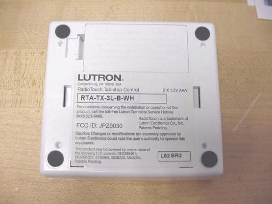
Click to zoom
Application Details
- Equipment Class
- DXT - Part 15 Low Power Transceiver, Rx Verified
- Date of Grant
- Feb 05, 2004
- Application Purpose
- Original Equipment
- Date of Application
- Feb 05, 2004
- Equipment Note
- Control Unit
- Frequency Range
- 418.00000000 - 418.00000000
- Country
- United States
Documents & Files
Document Text
Text extracted from the exhibit documents filed with the FCC. Open a document above to read the original.
Users Manual
Attention Contractors... Installer’s Guide Addendum for Tabletop Transmitters A Step-by-Step Guide for Installing, and Operating Tabletop Transmitters for use with a Lutron RadioTouch TM Visual Environment Control System 1234 5678 9101112 13141516 CLASS 2 LOW VOLTAGE WIRING 12345 Power Status Program Burn-In 123 Sivoia Cntrl 1Sivoia Cntrl 2 RTA-RX-F-SC Radio Frequency Controller LISTED 243C Ind. Cont. Eq. Coopersburg, PA 18036 STATUS INDICATOR OPERATION ON - Burn-in Mode Slow Blink -Normal Operation Mode Fast Blink - Program Mode Very Fast Blink - Receiving RF Data RadioTouch 12 345678910 11 12 13 14 15 16 Occ. Com Signal 15V24V Circuit Com Sw Closure 1Sw Closure 2Sw Closure 3Sw Closure 4Sw Closure 5 Closure Com 0-10 Purple 0-10 Gray Receiver Settings Terminal connections are Class 2. TM Occ. Sensor 0-10 V ShadeSwitch Closures 12345 Powered When Lit Status Indicator Program Button Burn-in Button RECEIVER SWITCH SETTINGS 1. UP-Preset LockDN.-Preset Adj. 2. UP-Occ. SensorDN.-Emerg. Set. 3. UP-FDB ModeDN.-ECO Mode 4. UP-OFFDN.-Min. Light 5. UP-Auto ONDN.-Manual ON See Installers Guide for System Addressing and Programming Instructions ® 123 Shade Settings SHADE SWITCH SETTINGS 1. UP-A/C ShadesDN.-Normal Oper. PS Signal © 2000-2002 Lutron Electronics Co., Inc. 2 RadioTouchTabletop Transmitter Addendum Hardware Installation RadioTouch 1234 5678 9101112 13141516 CLASS 2 LOW VOLTAGE WIRING 12345 Power Status Program Burn-In 123 Sivoia Cntrl 1Sivoia Cntrl 2 RTA-RX-F-SC Radio Frequency Controller LISTED 243C Ind. Cont. Eq. Coopersburg, PA 18036 STATUS INDICATOR OPERATION ON - Burn-in Mode Slow Blink -Normal Operation Mode Fast Blink - Program Mode Very Fast Blink - Receiving RF Data RadioTouch 12 345678910 11 12 13 14 15 16 Occ. Com Signal 15V24V Circuit Com Sw Closure 1Sw Closure 2Sw Closure 3Sw Closure 4Sw Closure 5 Closure Com 0-10 Purple 0-10 Gray Receiver Settings Terminal connections are Class 2. TM Occ. Sensor 0-10 V ShadeSwitch Closures 12345 Powered When Lit Status Indicator Program Button Burn-in Button RECEIVER SWITCH SETTINGS 1. UP-Preset LockDN.-Preset Adj. 2. UP-Occ. SensorDN.-Emerg. Set. 3. UP-FDB ModeDN.-ECO Mode 4. UP-OFFDN.-Min. Light 5. UP-Auto ONDN.-Manual ON See Installers Guide for System Addressing and Programming Instructions ® 123 Shade Settings SHADE SWITCH SETTINGS 1. UP-A/C ShadesDN.-Normal Oper. PS Signal © 2000-2002 Lutron Electronics Co., Inc. Addressing a Tabletop Transmitter Each column of buttons on the tabletop transmitter must be addressed to the Controller that you wish to control with that column. Addressing Columns of Buttons Step A- Press and release the programming button on the Controller. After the button is pressed the lights will cycle up and down for 3 seconds to notify you that you are in programming mode, and settle at 50% light output. If you are using an RTA-RX-SW the lights will cycle OFF and ON. The Status LED will be in fast blink mode. Press and hold this button Step B - While in programming mode press the corresponding button in the column that you want to control the receiver and hold for 5 seconds (see Transmitter diagrams below). The Controller will flash or cycle the lights OFF and ON when the transmitter is added. If no lights are being controlled by the receiver, you will not get visual feedback. Step C - Press the programming button again to exit from programming mode. The lights will go to high end and the Status LED will return to slow blinkmode. If you are using an RTA-RX-SW the lights will cycle OFF and ON. To test the tabletop transmitter for lights, press any button in the column added on the tabletop transmitter and verify that the lights respond. For Sivoia®shades, press any button and see that the shades move. If no response return to step A and be sure to hold the buttons for 5 seconds while in step B. Step D - Repeat steps A through C for each column you need to address to a Controller. Programming button Status LED Step A & C Press and hold this button Press and hold this button Step B - Columns of buttons Two button Switch ClosureThree button Switch Closure Dimmable LightsNon-dim Lights Four button Switch ClosureFive button Switch Closure 3 RadioTouchTabletop Transmitter Addendum Hardware Installation RadioTouch Deleting a Tabletop Transmitter Each column of buttons on the tabletop transmitter must be deleted separately from the Controller that you no longer wish to control. Deleting Columns of Lights Step A- Press and release the programming button on the Controller. After the button is pressed the lights will cycle up and down for 3 seconds to notify you that you are in programming mode, and settle at 50% light output. If you are using an RTA-RX-SW the lights will cycle OFF and ON. The Status LED will be in fast blink mode. Step B - While in programming mode press the corresponding buttons in the column that you want to delete from the Controller and hold for 5 seconds (see Transmitter diagrams below). The Controller will flash the lights when the transmitter is deleted. If no lights are being controlled by the Controller, you will not get visual feedback. Step C - Press the programming button again to exit from programming mode. The lights will go to high end or turn ON, and the Status LED will return to slow blink mode. To test the Tabletop Transmitter press any button on the transmitter in the column that has been deleted and verify that the lights or shades do not respond. Step D - Repeat for each row you need to delete from a Controller. 1234 5678 9101112 13141516 CLASS 2 LOW VOLTAGE WIRING 12345 Power Status Program Burn-In 123 Sivoia Cntrl 1Sivoia Cntrl 2 RTA-RX-F-SC Radio Frequency Controller LISTED 243C Ind. Cont. Eq. Coopersburg, PA 18036 STATUS INDICATOR OPERATION ON - Burn-in Mode Slow Blink -Normal Operation Mode Fast Blink - Program Mode Very Fast Blink - Receiving RF Data RadioTouch 12 345678910 11 12 13 14 15 16 Occ. Com Signal 15V24V Circuit Com Sw Closure 1Sw Closure 2Sw Closure 3Sw Closure 4Sw Closure …
Text truncated - open the document above for the full version.
Attestation Statements
6 th February, 2004 Underwriters Laboratories, Inc. 1285 Walt Whitman Road Melville, NY 11747-3081 Attn: Mr. Joe Danisi Subject: Request for Confidentiality for RTA-TX JPZ0030 Dear Joe, This letter is to formally request confidentiality per the FCC Rules 47 CFR Chapter 1, subpart C, section 0.459 - requests that materials or information submitted to the Commission be withheld from public inspection. For base models RTA-TX, the following items are Lutron Electronics Co., Inc. confidential information that must be withheld from public inspection by potential competitors to protect our business. 1. Schematics 2. Operational Description Thank you for your cooperation. Sincerely, R. S. Spehalski Engineering Leader
Block Diagram
JPZ0030 Lutron project 701 RTA-TX Block Diagram 2 x 1.5 VDC AAA alkaline b atteries DC-DC Converter Up to 500 kHz +5V Circuit Common Microcontroller LED and Switch Matrix +5V Reset Controller +5V Receive Data Transmit Data +5V antenna T/R switch Low Noise Amplifier filter X Local Oscillator 407.3MHz mixer IF strip 10.7MHz Data slicer Receive Data Transmit Enable Power Amplifier Transmit Oscillator 418MHz Transmit Enable Transmit Data 32 MHz OSC
External Photos
Exterior Photos Lutron Electronics Co., Inc. Project # 701, RTA-TX JPZ0030 12/29/03
ID Label/Location Info
ID location Lutron Electronics Co., Inc. Project # 701, RTA-TX JPZ0030 12/29/03
Internal Photos
Interior Photos Lutron Electronics Co., Inc. Project # 701, RTA-TX JPZ0030 01/09/04 CONFIDENTIAL INFORMATION
Test Report
Project: 03ME16541 File: NC2219 Date: 1/13/2004 Model: RTA-TX FCC ID: JPZ0030 Test Report On Electromagnetic Compatibility Testing Copyright 2003 Underwriters Laboratories Inc. Underwriters Laboratories Inc. authorizes the above-named company to reproduce this Report provided it is reproduced in its entirety. Underwriters Laboratories Inc. A not-for-profit organization dedicated to public safety and committed to quality service for over 100 years 1285 Walt Whitman Rd. Melville, NY 11747 Tel: (631) 271-6200 Fax: (631) 439-6095 File Number: NC2219 Issued: 1/13/2004 Project Number: 03ME16541 Model Number: RTA-TX FCC ID: JPZ0030 ____________________________________________________________________________________________________ Test Report Details Tests Performed By: Underwriters Laboratories Inc. 1285 Walt Whitman Rd. Melville, NY 11747 Tests Performed For: Lutron Electronics Co. Inc. 7200 Suter Road Coopersburg, PA 18036 Applicant Contact: Mark Clouser Title: Field Application Specialist Phone: 610-282-3800 Fax: 610-282-0298 E-mail: [email protected] Test Report Date: 1/13/2004 Product Type: Control Unit Model Number: RTA-TX Sample Serial Number: Not Provided Sample Tag Number: 0546132001 Sample Receive Date: 17 December 2003 EUT Category: Radio Transmitter Testing Start Date: 17 December 2003 Date Testing Complete: 05 January 2004 Underwriters Laboratories Inc. reports apply only to the specific samples tested under stated test conditions. All samples tested were in good operating condition throughout the entire test program. It is the manufacturer's responsibility to assure that additional production units of this model are manufactured with identical electrical and mechanical components. Underwriters Laboratories Inc. shall have no liability for any deductions, inferences or generalizations drawn by the client or others from Underwriters Laboratories Inc. issued reports. This report shall not be used to claim, constitute or imply product certification, approval, or endorsement by NVLAP, A2LA, or any agency of the US government. This report may contain test results that are not covered by the NVLAP or A2LA accreditation. The scope of accreditation is limited to the specific tests that are listed on the NVLAP and/or A2LA certificates provided at the end of this report. ____________________________________________________________________________________________________ Page 2 of 39 Underwriters Laboratories Inc. 1285 Walt Whitman Rd. Melville, New York 11747 USA Tel.: 631 271- 6200 Fax: 631 439-6095 Rev. No 1.0 File Number: NC2219 Issued: 1/13/2004 Project Number: 03ME16541 Model Number: RTA-TX FCC ID: JPZ0030 ____________________________________________________________________________________________________ Report Directory 1.0 G E N E R A L - Product Description..........................................................................................4 1.1 Device Configuration During Test..............................................................................................................5 1.1.1 Equipment Used During Test:..............................................................................................................5 1.1.2 Input/Output Ports:...............................................................................................................................5 1.1.3 EUT Internal Operating Frequencies:..................................................................................................5 1.1.4 Power Interface:...................................................................................................................................6 1.2 EUT Operation Modes:...............................................................................................................................6 1.3 EUT Configuration Modes:.........................................................................................................................6 1.4 Block Diagram:...........................................................................................................................................7 1.5 Deviations from standard test methods.......................................................................................................7 1.6 Device Modifications Necessary for Compliance .......................................................................................7 1.7 Test Summary..............................................................................................................................................7 2.0 Conclusion:...................................................................................................................................8 3.0 FCC Labeling Information.......................................................................................................... 9 3.1 Identification...............................................................................................................................................9 3.2 Compliance information..............................................................................................................................9 3.3 Labeling.....................................................................................................................................................10 3.4 User information........................................................................................................................................12 4.0 Calibration of Equipment Used for Measurement....................................................................12 5.0 EMISSIONS TEST REGULATIONS.......................................................................................13 5.1.1 Conducted Emissions Tests................................................................................................................14 5.1.2 Cease Operation Within 5 Seconds...........................................................................................…
Text truncated - open the document above for the full version.
Test Setup Photos
C C e e a a s s e e O O p p e e r r a a t t i i o o n n i i n n < < 5 5 S S e e c c o o n n d d s s T T e e s s t t S S e e t t - - U U p p R R a a d d i i a a t t e e d d E E m m i i s s s s i i o o n n T T e e s s t t S S e e t t u u p p 3 3 0 0 M M H H z z t t o o 1 1 0 0 0 0 0 0 M M H H z z F F r r o o n n t t V V i i e e w w R R a a d d i i a a t t e e d d E E m m i i s s s s i i o o n n T T e e s s t t S S e e t t u u p p 3 3 0 0 M M H H z z t t o o 1 1 0 0 0 0 0 0 M M H H z z R R e e a a r r V V i i e e w w R R a a d d i i a a t t e e d d E E m m i i s s s s i i o o n n T T e e s s t t S S e e t t u u p p 1 1 G G H H z z t t o o 5 5 G G H H z z F F r r o o n n t t V V i i e e w w R R a a d d i i a a t t e e d d E E m m i i s s s s i i o o n n T T e e s s t t S S e e t t u u p p 1 1 G G H H z z t t o o 5 5 G G H H z z R R e e a a r r V V i i e e w w Occupied Bandwidth Test Set-Up
Contact Information
Applicant
Daniel Schlegel(Standards Compliance Supervisor)
Technical Contact
Lutron Electronics Co., Inc.Brian Reidy
[email protected]610-282-6509
7200 Suter Road · Coopersburg, Pennsylvania · United States
Non-Technical Contact
Lutron Electronics Co., Inc.Mark Clouser
[email protected]610-282-6755
Test Firm
Underwriters Laboratories, Inc.Rick Titus
Technical Specifications
| # | Rule Parts | Frequency Range | Power Output |
|---|---|---|---|
| 1 | 15C | 418 MHz - 418 MHz | - |
Other Applications from Lutron Electronics Company Inc
JPZ0161
Sep 03, 2026Wireless Interface
Equipment Class
DTS - Digital Transmission SystemJPZ0159
Aug 12, 2026Wireless Processor
Equipment Class
DTS - Digital Transmission SystemJPZ0158
Jul 27, 2026Copy of Wireless Processor
Equipment Class
DTS - Digital Transmission SystemJPZ0157
Mar 26, 2026LED Downlight
Equipment Class
DTS - Digital Transmission SystemJPZ0155
Sep 30, 2024LED Lighting Controller
Equipment Class
DTS - Digital Transmission System