JPZ0031Lighting Control Transceiver
Lutron Electronics Company Inc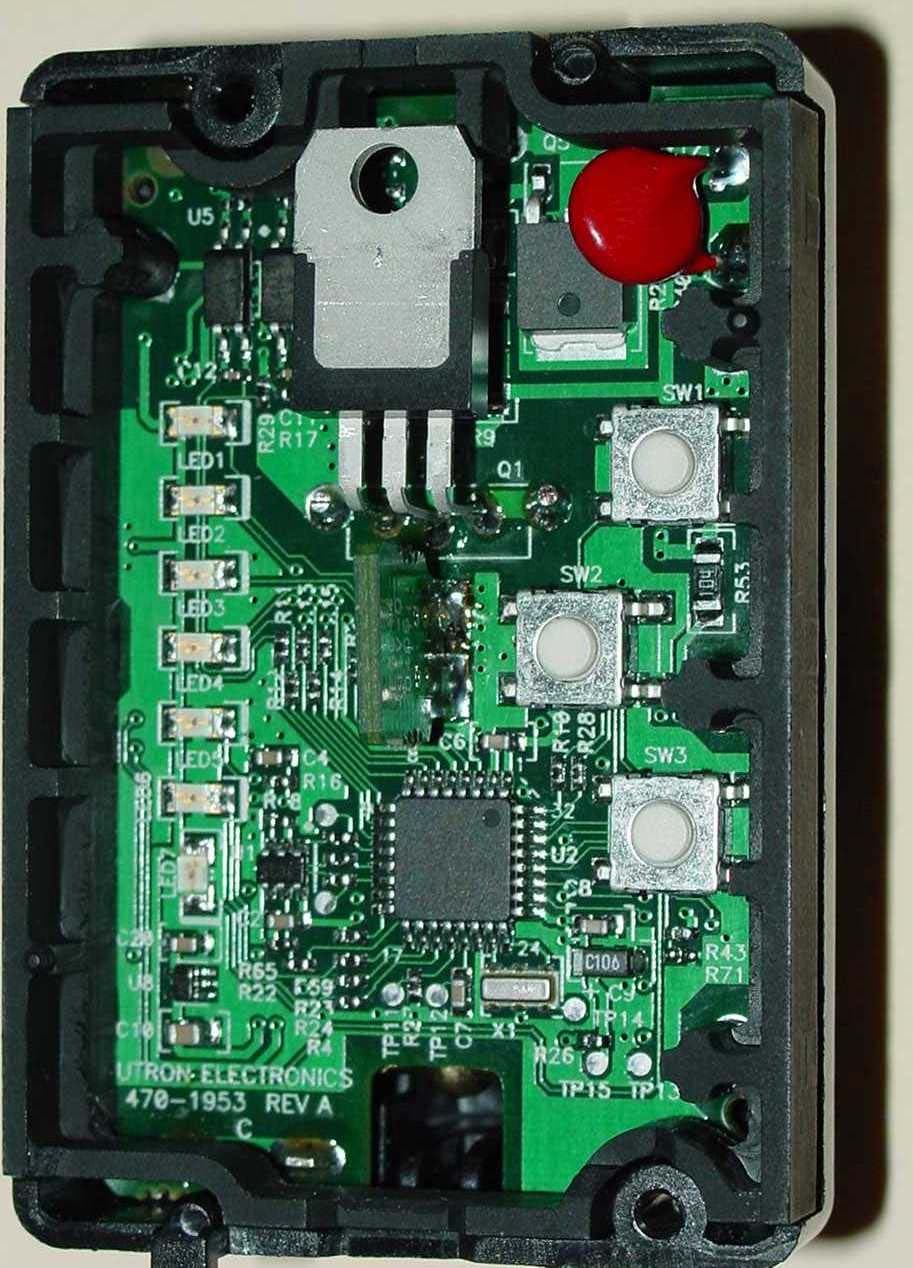
Click to zoom
Application Details
- Equipment Class
- DXT - Part 15 Low Power Transceiver, Rx Verified
- Date of Grant
- Jul 01, 2004
- Application Purpose
- Original Equipment
- Date of Application
- Jul 01, 2004
- Equipment Note
- Lighting Control Transceiver
- Frequency Range
- 418.00000000 - 418.00000000
- Country
- United States
Documents & Files
Document Text
Text extracted from the exhibit documents filed with the FCC. Open a document above to read the original.
Users Manual
Important Notes 1.Caution: To avoid overheating and possible damage to other equipment, do not use to control receptacles, fluorescent lighting fixtures, motor- operated or transformer-supplied appliances. 2.Install in accordance with all national and local electrical codes. 3.Do not paint dimmers or wallplates. 4.Clean with a soft damp cloth only. Do not use any chemical cleaners. 5.Do not use where total wattage is under recommended minimum load. 6.Do not exceed maximum load rating of dimmers. 7.In any 3-way/4-way circuit use only one Dimmer with up to 9 Accessory Dimmers. 8.Dimmer may not work with dioded lamps (Sylvania Designer 16™ or Philips PAR-16™). 9.Operate in ambient temperatures between 0°C (32°F) and 40°C (104°F). 10.Dimmer may feel warm to the touch during normal operation. 11.Recommended wallbox depth: 3 1 /2" deep recommended, 2 1 /2" deep minimum. 12.The range and performance of the RadioRA® System is highly dependent on a variety of complex factors such as: • Distance between system components • Geometry of the home • Construction of walls separating system components • Electrical equipment located near system components 13.Do not mix RadioRA®“A”(RA-) and “B” (RB-) products within the same system. “A” products and “B” products are not compatible. Installation Contents Single-Location Installation Installing one RadioRA® Dimmer to control light(s) from a single location. Two-Location Installation Installing one RadioRA® Dimmer and one Accessory Dimmer to control light(s) from two locations. Three-Location Installation Installing one RadioRA® Dimmer and two Accessory Dimmers to control light(s) from three locations. Multi-Location Installation For installations beyond Three-Location, call the Lutron Technical Support Center at 1-800-523-9466. Operation Using the RadioRA® Dimmer. Page 2 Page 4 Page 6 Page 8 Installation Instructions for Multi-Location Control Please Leave for Occupant Incandescent / 120V Halogen / Magnetic Low-Voltage RA-6D, RB-6D RA-10D, RB-10D Accessory Dimmer RA-AD, RB-AD 120 V 50/60 Hz Low-Voltage dimmers only: 14. Use models “RALV/RBLV” with only core and coil (magnetic) low-voltage transformers. Do not use to control solid-state (electronic) low-voltage transformers. 15.CAUTION: Operating a dimmed low-voltage circuit with all lamps inoperative or removed may result in current flow in excess of normal levels. To avoid possible transformer overheating and premature failure, Lutron strongly recommends the following: • Do not operate dimmed low-voltage circuits without operative lamps in place. • Replace burned-out lamps immediately. • Use transformers with thermal protection or fused primary windings to prevent transformer failure due to excess current. Before installation read instructions completely. Minimum Load Chart Dimmer Wattage Type of Load600W1000W Incandescent50 W50 W Magnetic Low-Voltage50 VA100 VA English P/N 044-050 Lutron Electronics Co., Inc. 7200 Suter Road Coopersburg, PA 18036-1299, U.S.A. Made and printed in the U.S.A. 6/04 P/N 044-050 Rev. A Operation Three-Location Installation Continued FCC Information NOTE: This equipment has been tested and found to comply with the limits for a Class B digital device, pursuant to part 15 of the FCC rules. These limits are designed to provide reasonable protection against harmful interference in a residential installation. This equipment generates, uses and can radiate radio frequency energy and, if not installed and used in accordance with the instructions, may cause harmful interference to radio or television reception, which can be determined by turning the equipment off and on, the user is encouraged to try to correct the interference by one or more of the following measures: • Reorient or relocate the receiving antenna. • Increase the separation between the equipment and receiver. • Connect the equipment into an outlet on a circuit different from that to which the receiver is connected. • Consult the dealer or an experienced radio/TV technician for help. Caution: Changes or modifications not expressly approved by Lutron Electronics Co. could void the user's authority to operate this equipment. Operation is subject to the following two conditions: (1) This device may not cause harmful interference, and (2) this device must accept any interference received, including interference that may cause undesired operation. Technical Assistance If you have questions concerning the installation or operation of this product, call the Lutron Technical Support Center. Please provide exact model number when calling. (800) 523-9466 (U.S.A., Canada, and the Caribbean) Other countries call (610) 282-3800 Fax (610) 282-3090 Visit our web site at www.lutron.com Step 7Mount and align dimmers. Attach Claro® or Satin ColorsTM wallplates (purchased separately). Step 8Turn power ON. Align dimmers. Ensure FASS TM switches are fully pushed in. Tighten screws until snug. Attach wallplates. ON OFF ON OFF ON OFF Troubleshooting Possible Cause • Front Accessible Service Switch (FASS TM) on the dimmers are switched to the left side. • Light bulb(s) burned out. • Breaker is off or tripped. • Blue wire on Accessory Dimmer not connected to the same color wire as the blue wire on Dimmer. • Black and Red wires on Dimmer are reversed. • Dimmer wired in middle of Accessory Dimmer string - must be on the line or load end of string. • Total wattage is under recommended minimum load. (See Important Note No.5.) Symptom Light does not turn on. Light turns ON and Dimmer works, but Accessory Dimmer does not work. Switch Tap on, Tap off Tap Twice Quickly - lights adjust rapidly to full. Press & Hold for 2 Seconds - Activates 10 second fade to off. Dimming Rocker Brighten Dim LEDs Indicate light level; glow softly as night light when light is off. (Not available on Accessory Dimmer.) FASS Front Accessible Service Switch For detailed instructions on programming the system, refer to the RadioRA ® Setup Guide that is included with an RF Signal…
Text truncated - open the document above for the full version.
Block Diagram
LUTRON ELECTRONICS CO., INC. Projec t: 771 June 2004 1 of 1 JPZ0031
ID Label/Location Info
LUTRON ELECTRONICS CO., INC. Project: 771 June 2004 1 of 1 JPZ0031 FCC ID JPZ0031
Internal Photos
June 2004 JPZ0031 Lutron project 771RA-6D Page 1 of 5 Internal Photo June 2004 JPZ0031 Lutron project 771RA-6D Page 2 of 5 Internal Photo June 2004 JPZ0031 Lutron project 771RA-6D Page 3 of 5 Internal Photo June 2004 JPZ0031 Lutron project 771RA-6D Page 4 of 5 Internal Photo June 2004 JPZ0031 Lutron project 771RA-6D Page 5 of 5 Internal Photo
Test Report
Underwriters Laboratories Inc. A not-for-profit organization dedicated 1285 Walt Whitman Rd. To public safety and committed to Melville, NY 11747 Quality service for over 100 years Tel: (631) 271-6200 Fax: (631) 439-6095 Project: 04ME04421 File: NC2219 Date: 6/2/04 Model: RA-6D FCC ID: JPZ0031 Test Report On Electromagnetic Compatibility Testing Copyright 2003 Underwriters Laboratories Inc. Underwriters Laboratories Inc. authorizes the above-named company to reproduce this Report provided it is reproduced in its entirety. File Number: NC2219 Issued: 6/02/04 Project Number: 04ME04421 Model Number: RA-6D FCC ID: JPZ0031 ____________________________________________________________________________________________________ Page 2 of 54 Underwriters Laboratories Inc. 1285 Walt Whitman Rd. Melville, New York 11747 USA Tel.: 631 271-6200 Fax: 631 439-6095 Rev. No 1.0 Test Report Details Tests Performed By: Underwriters Laboratories Inc. 1285 Walt Whitman Rd. Melville, NY 11747 Tests Performed For: Lutron Electronics Inc. 7200 Suter Road Coopersburg, PA 18036 Applicant Contact: Mark Clouser Title: Field Applications Specialist Phone: 610-282-3800 Fax: 610-282-0298 E-mail: [email protected] Test Report Date: 5/26/04 Product Type: Radio Frequency Controlled Dimmer Model Number: RA-6D Sample Serial Number: Not Provided Sample Tag Number: 0584944001 Sample Receive Date: 06 May 2004 EUT Category: Transceiver Testing Start Date: 14 May 2004 Date Testing Complete: 24 May 2004 Underwriters Laboratories Inc. reports apply only to the specific samples tested under stated test conditions. All samples tested were in good operating condition throughout the entire test program. It is the manufacturer's responsibility to assure that additional production units of this model are manufactured with identical electrical and mechanical components. Underwriters Laboratories Inc. shall have no liability for any deductions, inferences or generalizations drawn by the client or others from Underwriters Laboratories Inc. issued reports. This report shall not be used to claim, constitute or imply product certification, approval, or endorsement by NVLAP, A2LA, or any agency of the US government. This report may contain test results that are not covered by the NVLAP or A2LA accreditation. The scope of accreditation is limited to the specific tests that are listed on the NVLAP and/or A2LA certificates provided at the end of this report. File Number: NC2219 Issued: 6/02/04 Project Number: 04ME04421 Model Number: RA-6D FCC ID: JPZ0031 ____________________________________________________________________________________________________ Page 3 of 54 Underwriters Laboratories Inc. 1285 Walt Whitman Rd. Melville, New York 11747 USA Tel.: 631 271-6200 Fax: 631 439-6095 Rev. No 1.0 Report Directory 1.0 G E N E R A L - Product Description..........................................................................................4 1.1 Device Configuration During Test......................................................................................................5 1.1.1 Equipment Used During Test:......................................................................................................5 1.1.2 Input/Output Ports:.....................................................................................................................5 1.1.3 EUT Internal Operating Frequencies:...........................................................................................6 1.1.4 Power Interface:.........................................................................................................................6 1.2 EUT Operation Modes:......................................................................................................................6 1.3 EUT Configuration Modes:................................................................................................................6 1.4 Block Diagram:.................................................................................................................................7 1.5 Deviations from standard test methods................................................................................................7 1.6 Device Modifications Necessary for Compliance.................................................................................7 1.7 Test Summary...................................................................................................................................7 2.0 Conclusion:...................................................................................................................................8 3.0 FCC Labeling Information..........................................................................................................9 3.1 Identification.....................................................................................................................................9 3.2 Compliance information....................................................................................................................9 3.3 Labeling.........................................................................................................................................10 3.4 User information.............................................................................................................................12 4.0 Calibration of Equipment Used for Measurement....................................................................13 5.0 EMISSIONS TEST REGULATIONS........................................................................................13 5.1.1 Conducted Emissions Tests.......................................................................................................14 5.1.2 Cease Operation Within 5 Seconds............................................................................................28 5.1.3 Radiated Emissions Test (10 Meter Semi-Anechoic Chamber).....................................................31…
Text truncated - open the document above for the full version.
Test Setup Photos
C C o o n n d d u u c c t t e e d d E E m m i i s s s s i i o o n n T T e e s s t t S S e e t t - - U U p p Test Set-up Cease Operation < 5 Seconds Radiated Emission Test Set-up Front View 30 –1000MHz Radiated Emission Test Set-up Front View 1 –5GHz Radiated Emission Test Set-up Rear View 1 –5GHz P P u u l l s s e e T T r r a a i i n n T T e e s s t t S S e e t t - - U U p p O O c c c c u u p p i i e e d d B B a a n n d d w w i i d d t t h h T T e e s s t t S S e e t t - - U U p p
Contact Information
Applicant
Daniel Schlegel(Standards Compliance Supervisor)
Technical Contact
Lutron Electronics Co., Inc.Rober Bollinger
[email protected]610-282-6509
7200 Suter Road · Coopersburg, Pennsylvania · United States
Non-Technical Contact
Lutron Electronics Co., Ltd.Mark Crouser
[email protected]610-282-3800
Test Firm
Underwriters Laboratories, Inc.Rick Titus
Technical Specifications
| # | Rule Parts | Frequency Range | Power Output |
|---|---|---|---|
| 1 | 15C | 418 MHz - 418 MHz | - |
Other Applications from Lutron Electronics Company Inc
JPZ0161
Sep 03, 2026Wireless Interface
Equipment Class
DTS - Digital Transmission SystemJPZ0159
Aug 12, 2026Wireless Processor
Equipment Class
DTS - Digital Transmission SystemJPZ0158
Jul 27, 2026Copy of Wireless Processor
Equipment Class
DTS - Digital Transmission SystemJPZ0157
Mar 26, 2026LED Downlight
Equipment Class
DTS - Digital Transmission SystemJPZ0155
Sep 30, 2024LED Lighting Controller
Equipment Class
DTS - Digital Transmission System