JPZ0037Home Works tabletop radio frequency keypad control
Lutron Electronics Company Inc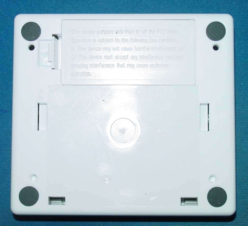
Click to zoom
Application Details
- Equipment Class
- DSC - Part 15 Security/Remote Control Transmitter
- Date of Grant
- Oct 19, 2005
- Application Purpose
- Original Equipment
- Date of Application
- Oct 19, 2005
- Equipment Note
- Home Works tabletop radio frequency keypad control
- Frequency Range
- 431.00000000 - 437.00000000
- Country
- United States
Documents & Files
Document Text
Text extracted from the exhibit documents filed with the FCC. Open a document above to read the original.
Users Manual
1 Please Read Before Installing RF Tabletop Keypads HRT- 5KP-A, -C 10KP-A, -C 15KP-A, -C 6LKP-A, -C 5RL-A, -C 10RL-A, -C 15RL-A, -C 6LRL-A, -C 120/127 V ~ , 50/60 Hz (9 V adapter, -A and -C models) Batteries: 2 AAA size, 1.5V each (-C models) Installation Instructions Overview RF Tabletop Keypads are for use with HomeWorkssys- tems. The keypad buttons are programmed with a per- sonal computer using the HomeWorksUtility. Up to 32 keypads, each with a unique address, can be assigned to each HomeWorksRF Processor. Important Notes Codes:Install in accordance with all local and national electrical codes. Power:Battery-powered models (-C only):Use only high quality alkaline batteries, two (2) size AAA, 1.5V each. Caution - Do notuse rechargeable batteries. Using improperly rated batteries could damage the RF Tabletop Keypad. All models (-A, -C):Use only the adapter provided by Lutron with your RF Tabletop Keypad. Caution - Using an adapter not rated for the following specifications could damage the key- pad and possibly overheat the adapter. • Input: 120/127 VAC, 50/60 Hz • Output: 9 VDC/300 mA Class 2 Environment:Ambient operating temperature: 32-104°F (0-40°C), 0-90% humidity, non-condensing. Indoor use only. Faceplates:Do not paint controls or faceplates. Cleaning:To clean, wipe with a clean damp cloth. DO NOTuse any chemical cleaning solutions. RF Device Placement:RF Tabletop Keypads must be located within 30 feet (10m) of an RF Signal Repeater or an RF Processor. Setup:RF Tabletop Keypads will not function until they are addressed and programmed. See the HomeWorks Utility online help. HRT-5KP HRT-5RL HRT-10KP HRT-10RL HRT-15KP HRT-15RL HRT-6LKP HRT-6LRL 2 Installation Battery Installation (-C Models) 1.Remove battery cover. 2.Install batteries as shown. Use two 1.5V AAA alkaline batteries only. 3.Replace battery cover. Adapter Installation (All Models) Mounting Diagram RF Tabletop Keypads may be wall mounted using the supplied wall bracket. Plug in power cord and adapter 1. Attach wall bracket to wall using the supplied screws and wall anchors. 2.Wrap excess adapter cord (if using) around the cord holder. Align keypad and snap onto wall bracket. Note: Battery-powered models only • The RF Tabletop Keypad goes to “sleep” after a short period of inactivity. • Press any button to “wake up” the keypad. Refer to battery installation diagram molded inside battery compartment. 1.Find a suitable location for the RF Tabletop Keypad.Place the keypad in a convenient and accessible location. Note:RF Keypads must be located within 30 feet (10m) of an RF Signal Repeater or an RF Processor. 2.Apply power to the RF Tabletop Keypad. 3 SymptomCause and Action No power available to keypad. • Verify adapter is plugged in. Faulty adapter. • Replace adapter. Dead, low, or no batteries in keypad. • Replace the batteries. Batteries are incorrectly installed. • Install batteries as indicated inside the keypad. Batteries are not making contact with the battery terminals. • Adjust the batteries so they make contact with the ter- minals. Batteries are low. • Replace the batteries. Keypad is out of system communications range. • Move the keypad to within 30 ft. (10m) of an RF Signal Repeater or RF Processor. Button being pressed has not been programmed. • See the HomeWorksUtility online help for programming details. Keypad has not been addressed. • See the HomeWorksUtility online help for setup details. Keypad has an address, but does not have a valid pro- gramming database. • See the HomeWorksUtility online help for programming details. LEDs on an adapter-powered keypad do not light. A battery-powered keypad will not “wake up” when a but- ton is pressed. A battery-powered keypad “wakes up” but goes to “sleep” quickly after a button press. A battery-powered keypad’s LEDs cycle up and down dur- ing “wake up”, but the system lights do not respond to but- ton presses. Button presses on keypad cause the keypad to quickly flash all its LEDs simultaneously. Button presses on keypad cause the keypad to slowly flash all its LEDs simultaneously. Troubleshooting Guide RF Keypads will not control other system devices until the keypads are addressed and programmed. See the HomeWorks ®Utility online help. Lutron Electronics Co., Inc. 7200 Suter Road Coopersburg, PA 18036-1299 Made and printed in the U.S.A. 02/03 P/N 043-112 Rev. B LIMITED WARRANTY Lutron will, at its option, repair or replace any unit that is defective in materials or manufac- ture within two years after purchase. For warranty service, return unit to place of purchase or mail to Lutron at 7200 Suter Rd., Coopersburg, PA 18036-1299, postage pre-paid. Telephone the Lutron Technical Support Center toll free at 800-523-9466. After the two year period, a pro-rated warranty applies to this product until eight years after the purchase. For more infor- mation regarding this warranty contact your Lutron representative. THIS WARRANTY IS IN LIEU OF ALL OTHER EXPRESS WARRANTIES, AND THE IMPLIED WARRANTY OF MERCHANTABILITY IS LIMITED TO TWO YEARS FROM PUR- CHASE. THIS WARRANTY DOES NOT COVER THE COST OF INSTALLATION, REMOVAL OR REINSTALLATION, OR DAMAGE RESULTING FROM MISUSE, ABUSE, OR IMPROPER OR INCORRECT REPAIR, OR DAMAGE FROM IMPROPER WIRING OR INSTALLATION. THIS WARRANTY DOES NOT COVER INCIDENTAL OR CONSEQUEN- TIAL DAMAGES. LUTRON’S LIABILITY ON ANY CLAIM FOR DAMAGES ARISING OUT OF OR IN CONNECTION WITH THE MANUFACTURE, SALE, INSTALLATION, DELIVERY, OR USE OF THE UNIT SHALL NEVER EXCEED THE PURCHASE PRICE OF THE UNIT. This warranty gives you specific legal rights, and you may also have other rights which vary from state to state. Some states do not allow limitations on how long an implied warranty lasts, so the above limitation may not apply to you. Some states do not allow the exclusion or limi- tation of incidental or consequential damages, so the above limitation or exclusion may not apply to you. This product may be covered by one or more of the following U.S. patents…
Text truncated - open the document above for the full version.
Block Diagram
JPZ0037 HRT-10KP Page 1 of 1 Block Diagram Sep, 2005 F 1105I 1106
Cover Letter(s)
22 nd Sep, 2005 Subject: Request for Confidentiality – HRT-10KP JPZ0037 Dear Sir or Madam: This letter is to formally request confidentiality per the FCC Rules 47 CFR Chapter 1, subpart C, section 0.459 - requests that materials or information submitted to the Commission be withheld from public inspection. For model HRT-10KP, the following items are Lutron Electronics Co., Inc. confidential information that must be withheld from public inspection by potential competitors to protect our business. 1. Schematics 2. Operational Description Thank you for your cooperation. Sincerely, R. S. Spehalski Engineering Leader
Cover Letter(s)
8th Sep, 2005 Attn: Reviewing Engineer Federal Communications Commission 7435 Oakland Mills Road Columbia, MD 21046 RE: LETTER OF AGENT AUTHORIZATION- HRT-10KP JPZ0037 Dear Sir or Madam: We, the undersigned, hereby authorize MET Laboratories, Inc. to act on our behalf in all matters relating to application for equipment authorization, including the signing of all documents relating to these matters. We also hereby certify that no party to the application authorized hereunder is subject to the denial of benefits, including FCC benefits, pursuant to Section 5301 of the Anti-Drug Abuse Act of 1988, 21 U.S.C.853(a). This agreement expires one year from the current date. Sincerely, Mark Clouser Senior Engineering Technician
Cover Letter(s)
DOC-FCC009 4/14/2005 Page 1 of 3 FEDERAL COMMUNICATIONS COMMISSION - FCC FORM 731 APPLICATION FOR EQUIPMENT AUTHORIZATION Approved by OMB 3060 - 0934 Expires 02/28/2005 Item 1. Applicant's complete, legal business name: Lutron Electronics Co., Inc. Item 2. Applicant's mailing address Line 1: 7200 Suter Road P.O.Box: 900 City: Coopersburg State: PA Country (if foreign address): Zip/Postal Code: 18036-1299 Item 3. FCC ID: JPZ0037 Grantee code: JPZ Equipment Product Code (14 characters maximum): 0037 Item 4. Person at the applicant's address to receive grant or for contact: First Name: Mark Last Name: Clouser Telephone: 610-282-3800 Ext: 6755 Title: Senior Engineering Technician E-mail: [email protected] Fax No: 610-282-6457 Item 5. Instead of Applicant, the original Grant is authorized to be mailed to: Item 6. Technical Contact: Firm Name: Lutron Electronics Co., Inc. Telephone: Ext: 6509 Fax No: First Name: Robert Middle Initial: Last Name: Bollinger Address Line 1: P.O.Box: Address Line 2: City: Country (if foreign address): Zip/Postal Code: E-mail: [email protected] Item 7. Non-Technical Contact: Firm Name: Lutron Electronics Co., Inc. Telephone: Ext: 7424 Fax No: First Name: Robert Middle Initial: Last Name: Spehalski Address Line 1: P.O.Box: Address Line 2: City: Country (if foreign address): Zip/Postal Code: E-mail: Item 8. * Does this application include a request for confidentiality for any portion(s) of the data contained in this application pursuant to 47 CFR § 0.459 of the Commission Rules? If "Yes" see instructions. (please mark as appropriate) : Yes Ο No Item 9. Does the applicant request that the Commission defer grant of this application pursuant 47 CFR § 0.457(d)(1)(ii)? (See instructions) No If so, specify date when grant may be issued (MM/DD/YYYY format): Item 10. * Equipment Class: * Description of Product as it is Marketed: (NOTE: This text will appear below the equipment class on the grant) Item 11. * Application is for: (please mark as appropriate) : Original Equipment (See instructions) Ο Change in identification of presently authorized equipment: Original FCC ID: Grant Date (MM/DD/YYYY format): Ο Class II permissive change or modification of presently authorized equipment (See instructions) Item 12. Is the equipment in this application: * (a) a composite device subject to an additional equipment authorization? * (b) part of a system that operates with, or is marketed with, another device that requires an equipment authorization? If either of the above questions is answered "Yes" complete section 12(c). Ο Yes : No : Yes Ο No DOC-FCC009 4/14/2005 Page 2 of 3 (c) The related application: : has been granted under the FCC ID listed to the right Ο is in the process of being filed under the FCC ID listed to the right Ο is pending with the FCC under the FCC ID listed to the right FCC ID JPZ0034 Item 13. Name of test firm and contact person on file with the FCC, if different from applicant or contact person: Firm Name: Last Name: Telephone Ext Fax No. E-mail: Item 14. Enter any text that you would like to appear at the bottom of the Grant of Equipment Authorization. Read each certification carefully before answering and signing this application Equipment Specifications: Rule Part Frequency Range (MHz) Power (W) Frequency Tolerance and Units Emission Designator Note Codes 15 431-437 MHz 100uW +/- 0.25% F7D WILLFUL FALSE STATEMENTS MADE ON THIS FORM ARE PUNISHABLE BY FINE AND IMPRISONMENT (U.S. CODE, TITLE 18, SECTION 1001), AND/OR REVOCATION OF ANY STATION LICENSE OR CONSTITUTION PERMIT (U.S. CODE, TITLE 47, SECTION 312(a)(1)), AND/OR FORFEITURE (U.S. CODE, TITLE 47, SECTION 503). Item 15. *SECTION 5301 (ANTI-DRUG ABUSE) CERTIFICATION: The applicant must certify that neither the applicant nor any party to the application is subject to a denial of Federal benefits, that include FCC benefits, pursuant to Section 5301 of the Anti-Drug Abuse Act of 1988, 21 U.S.C. § 862 because of a conviction for possession or distribution of a controlled substance. See 47 CFR 1.2002(b) for the definition of a "party" for these purposes. Does the applicant or authorized agent so certify? : Yes Ο No Item 16. APPLICANT/AGENT CERTIFICATION: I certify that I am authorized to sign this application. All of the statements herein and the exhibits attached hereto, are true and correct to the best of my knowledge and belief. IN accepting a Grant of Equipment Authorization issued by the FCC as a result of the representations made in this application, the applicant is responsible for (1) labeling the equipment with the exact FCC ID specified in this application, (2) compliance statement labeling pursuant to the applicable rules, and (3) compliance of the equipment with the applicable technical rules. If the applicant is not the actual manufacturer of the equipment, appropriate arrangements have been made with the manufacturer to ensure that production units of this equipment will continue to comply with the FCC's technical requirements. Authorizing an agent to sign this application, is done solely at the applicant's discretion; however, the applicant remains responsible for all statements in this application. If an agent has signed this application on behalf of the applicant, a written letter of authorization which includes information to enable the agent to respond to the above section 5301 (Anti-Drug Abuse) Certification statement has been provided by the applicant. It is understood that the letter of authorization must be submitted to the FCC upon request, and that the FCC reserves the right to contact the applicant directly at any time. * Signature of Authorized Person Filing: Marie Ann Confroy Title of authorized signature: TCB Administrator Complete items below if an agent signs the application Firm Name: Address Line 1: P.O.Box: Address Line 2: City: Country (if foreign address): Zip/Postal Code: Person at above address to receive Grant: First Name Last Name: Title: Mail Stop: NOTE: An asterisk…
Text truncated - open the document above for the full version.
External Photos
External photos Sep 2005 JPZ0037 Lutron: HRT-10KP Page 1 of 2 F 1105 I 1106 External photos Sep 2005 JPZ0037 Lutron: HRT-10KP Page 2 of 2 F 1105 I 1106
ID Label/Location Info
ID label location Sep, 2005 JPZ0037 Lutron: HRT-10KP Page 1 of 2
Internal Photos
Internal photos Sep 2005 JPZ0037 Lutron: HRT-10KP Page 1 of 2 F 1105 I 1106 Internal photos Sep 2005 JPZ0037 Lutron: HRT-10KP Page 2 of 2 F 1105 I 1106
Operational Description
17th Oct, 2005 Attn: Technical Reviewer RE: Clarifications for submission JPZ0037 Dear technical reviewer, In regards to clarify the following for Lutron submission HRT-10KP (MET 18241): (1) A manually operated transmitter shall employ a switch that will automatically deactivate the transmitter within not more than 5 seconds of being released. (2) A transmitter activated automatically shall cease transmission within 5 seconds after activation. Lutron HRT-10KP keypads incorporate a micro-processor controlled radio transceiver which terminates all transmissions less than 5 seconds after initiation. (3) Periodic transmissions at regular predetermined intervals are not permitted. However, polling or supervision transmissions to determine system integrity of transmitters used in security or safety applications are allowed if the periodic rate of transmission does not exceed one transmission of not more than one second duration per hour for each transmitter. There are no predetermined periodic transmissions. 1) The unit was tested in three orthogonal planes when applicable. The EUT is a table-top device and was placed on the FCC turn-table in its normal operating position; therefore, testing in three planes is not applicable. 2) The EUT antenna position was adjusted to maximize emissions. The EUT possesses an antenna that is fixed and cannot be adjusted. 3) The User controls were adjusted to maximize emissions. There are no user controls. 4) The Input signals were adjusted to maximize emissions. There are no input signals. Regards, Mark Clouser Senior Engineering Technician
Test Report
RADIATION SCIENCES INC. 1986.01 TEST REPORT NO. RSI-2790E ELECTROMAGNETIC EMISSION EVALUATION OF THE LUTRON ELECTRONICS MODEL #: HRT-xKP-yy FCC PART 15, SUBPART B AND C 5 OCTOBER 2005 PREPARED FOR : Lutron Electronics 7200 Suter Road Coopersburg, PA 18036 SUBMITTED BY : Radiation Sciences Inc. 3131 Detwiler Road Harleysville, PA 19438 PREPARED BY : ____________________ Ron Smith EMC Test Engineer Radiation Sciences Inc. REVIEWED BY : ____________________ Daniel J. Signore President Radiation Sciences Inc. RADIATION SCIENCES INC. RSI-2790E i TABLE OF CONTENTS SECTION TITLE PAGE Table of Contents i List of Figures ii Administrative Data iii Summary of Test Results iv 1.0 INTRODUCTION 1 2.0 DESCRIPTION OF THE EQUIPMENT UNDER TEST (EUT) 2 3.0 TEST INSTRUMENTATION 3 4.0 TEST RESULTS 4 4.1 Conducted Emissions Test Results 4 4.2 Radiated Emissions Test Results 15 4.3 Bandwidth Measurements 29 5.0 Conclusions 32 RADIATION SCIENCES INC. RSI-2790E ii LIST OF FIGURES FIGURE TITLE PAGE FIGURE 1 Conducted Emissions Test Setup Diagram 5 FIGURE 2 Conducted Emissions Test Setup Photographs 6 FIGURE 3 Conducted Emissions Test Results Phase Line, Tx431MHz 7 FIGURE 4 Conducted Emissions Test Results Neutral Line, Tx431MHz 8 FIGURE 5 Conducted Emissions Test Results Phase Line, Rx431MHz 9 FIGURE 6 Conducted Emissions Test Results Neutral Line, Rx431MHz 10 FIGURE 7 Conducted Emissions Test Results Phase Line, Tx437MHz 11 FIGURE 8 Conducted Emissions Test Results Neutral Line, Tx437MHz 12 FIGURE 9 Conducted Emissions Test Results Phase Line, Rx437MHz 13 FIGURE 10 Conducted Emissions Test Results Neutral Line, Rx437MHz 14 FIGURE 11 Duty Cycle Correction Factor 16 FIGURE 12 Radiated Emissions Test Setup Diagram 17 FIGURE 13 Radiated Emissions Test Setup Photographs 18 FIGURE 14 Radiated Emissions Test Results Data, Rx, Mode, 431MHz 19 FIGURE 15 Radiated Emissions Test Results Graph, Rx, Mode, 431MHz 20 FIGURE 16 Radiated Emissions Test Results Data, Rx, Mode, 437MHz 21 FIGURE 17 Radiated Emissions Test Results Graph, Rx, Mode, 437MHz 22 FIGURE 18 Radiated Emissions Test Results Data, CW, Tx Mode, 431MHz, Horiz. 23 FIGURE 19 Radiated Emissions Test Results Data, CW, Tx Mode, 431MHz, Vert. 24 FIGURE 20 Radiated Emissions Test Results Data, CW, Tx Mode, 437MHz, Horiz. 25 FIGURE 21 Radiated Emissions Test Results Data, CW, Tx Mode, 437MHz, Vert. 26 FIGURE 22 Intentional Radiator Test Results Data, CW, Tx Mode, 431MHz 27 FIGURE 23 Intentional Radiator Test Results Data, CW, Tx Mode, 437MHz 28 FIGURE 24 Bandwidth Test Results Data, CW, Tx Mode, 431MHz 30 FIGURE 25 Bandwidth Test Results Data, CW, Tx Mode, 437MHz 31 RADIATION SCIENCES INC. RSI-2790E iii ADMINISTRATIVE DATA TEST PERFORMED: Measurements of Radiated RF and Conducted Emissions. PURPOSE OF TEST : To evaluate the ElectroMagnetic Emission (EME) characteristics of the Equipment Under Test (EUT) with respect to Subpart B and C of Part 15 of the Federal Communications Commission (FCC) Rules for intentional and unintentional radiators. EQUIPMENT UNDER TEST (EUT) : Model Number: HRT-xKP-yy Serial Number: nsn CONTRACT : Purchase Order Number: 0047111 TEST PERIOD : TEST FACILITY: Radiation Sciences Incorporated (RSI), EMC Test Laboratory, located at: 3131 Detwiler Road, Harleysville, Pennsylvania 19438. TEST PERSONNEL AND COORDINATORS : Radiation Sciences Inc. Lutron Electronics Ron Smith Mark Clouser RADIATION SCIENCES INC. RSI-2790E iv SUMMARY OF TEST RESULTS The Model #: HRT-xKP-yy, configured as described herein, FULLY COMPLIES WITH THE REQUIREMENTS SET FORTH IN SUBPART B AND C OF PART 15 OF THE FEDERAL COMMUNICATIONS COMMISSION (FCC) RULES FOR INTENTIONAL AND UNINTENTIONAL RADIATORS. The test results contained in this report represent emission and/or immunity characteristics of only the product(s) (model and serial no.) tested. Radiation Sciences Inc. makes no claim that identical test results will be obtained for future tests of the same model/equipment. RADIATION SCIENCES INC. RSI-2790E 1 1.0 INTRODUCTION This document is a report of tests to determine the EME characteristics of the Model #: HRT- xKP-yy, presented by Lutron Electronics of Coopersburg, Pennsylvania. The purpose of the testing was to evaluate the EMC characteristics of the test sample with re- spect to Subpart B and C of Part 15 of the FCC Rules for intentional and unintentional radiators. All test procedures used meet the requirements of the American National Standards Institute Procedure C63:4: "Methods of Measurement of Radio-Noise Emissions from Low-Voltage Electrical and Electronic Equipment in the Range of 9kHz to 40GHz", 2003. RADIATION SCIENCES INC. RSI-2790E 2 2.0 DESCRIPTION OF THE TEST SAMPLE : The Model # HRT-xKP-yy, manufactured by Lutron Electronics of Coopersburg PA, is a Home Works tabletop radio frequency key pad control. Hereinafter, the Model # HRT-xKP-yy, will be referred to as the EUT (Equipment Under Test). RADIATION SCIENCES INC. RSI-2790E 3 3.0 TEST INSTRUMENTATION RSI CAL INV DUE NO. DESCRIPTION MANUFACTURER MODEL # SERIAL # DATE 31 SPEC ANALYZER ADVANTEST R3271 J003583 10/27/2005 32.1 SPEC. ANALY. H.P. 8566B 3638A08767 8/13/2006 33.1 SPEC. ANALY. DISPLY H.P. 3701A22258 8/13/2006 52 ANTENNA EMCO 3115 2425 6/10/2007 75 ANTENNA TENSOR 4108 204 6/11/2007 80 ANTENNA AMP.RES.Assoc. AT1000 4094-025 6/14/2007 391 RECEIVER R & S ESVP 861744/015 12/15/2005 501 MINI MAST EMCO 2075-2 0002-2278 502 TURNTABLE EMCO 2065-1.21 0001-2156 503 CONTROLLER EMCO 2090 0001-1489 708 40ft Cable RG-223 PASTERNACK BNC TO BNC N/A 9/23/2006 712 20ft Cable RG-223 PASTERNACK BNC TO BNC N/A 9/16/2006 IF CAL DUE DATE = BLANK FIELD Calibration is not required for this item. Equipment not used to obtain a final reading (i.e. transmitting antenna). RADIATION SCIENCES INC. RSI-2790E 4 4.0 TEST RESULTS 4.1 Conducted Power Line Measurements, Paragraph 15.107 Conducted power line measurements were recorded for the Model HRT-xKP-yy. The test setup diagram is shown in Figure 1 and a photograph is shown in Figu…
Text truncated - open the document above for the full version.
Test Setup Photos
Biconical antenna freq. 30-200MHz Log-Periodic Freq. 200-1000MHz 3115 Double Ridge wave Guide 1-18GHz EUT test configuration Radiated Emissions Test Setup Photographs Figure EUT 80cm From LISN EUT 40cm from vertical ground plane Conducted Emissions Test Setup Photographs Figure
Contact Information
Applicant
Daniel Schlegel(Standards Compliance Supervisor)
Test Firm
Radiation Sciences Inc.Daniel Signore
Technical Specifications
| # | Rule Parts | Frequency Range | Power Output | Emission | Tolerance |
|---|---|---|---|---|---|
| 2 | 15.231 | 431 MHz - 437 MHz | 100.00 µW | F7D | 0.25 % |
Other Applications from Lutron Electronics Company Inc
JPZ0161
Sep 03, 2026Wireless Interface
Equipment Class
DTS - Digital Transmission SystemJPZ0159
Aug 12, 2026Wireless Processor
Equipment Class
DTS - Digital Transmission SystemJPZ0158
Jul 27, 2026Copy of Wireless Processor
Equipment Class
DTS - Digital Transmission SystemJPZ0157
Mar 26, 2026LED Downlight
Equipment Class
DTS - Digital Transmission SystemJPZ0155
Sep 30, 2024LED Lighting Controller
Equipment Class
DTS - Digital Transmission System