JPZ0038Tabletop Radio Frequency Key Pad Control
Lutron Electronics Company Inc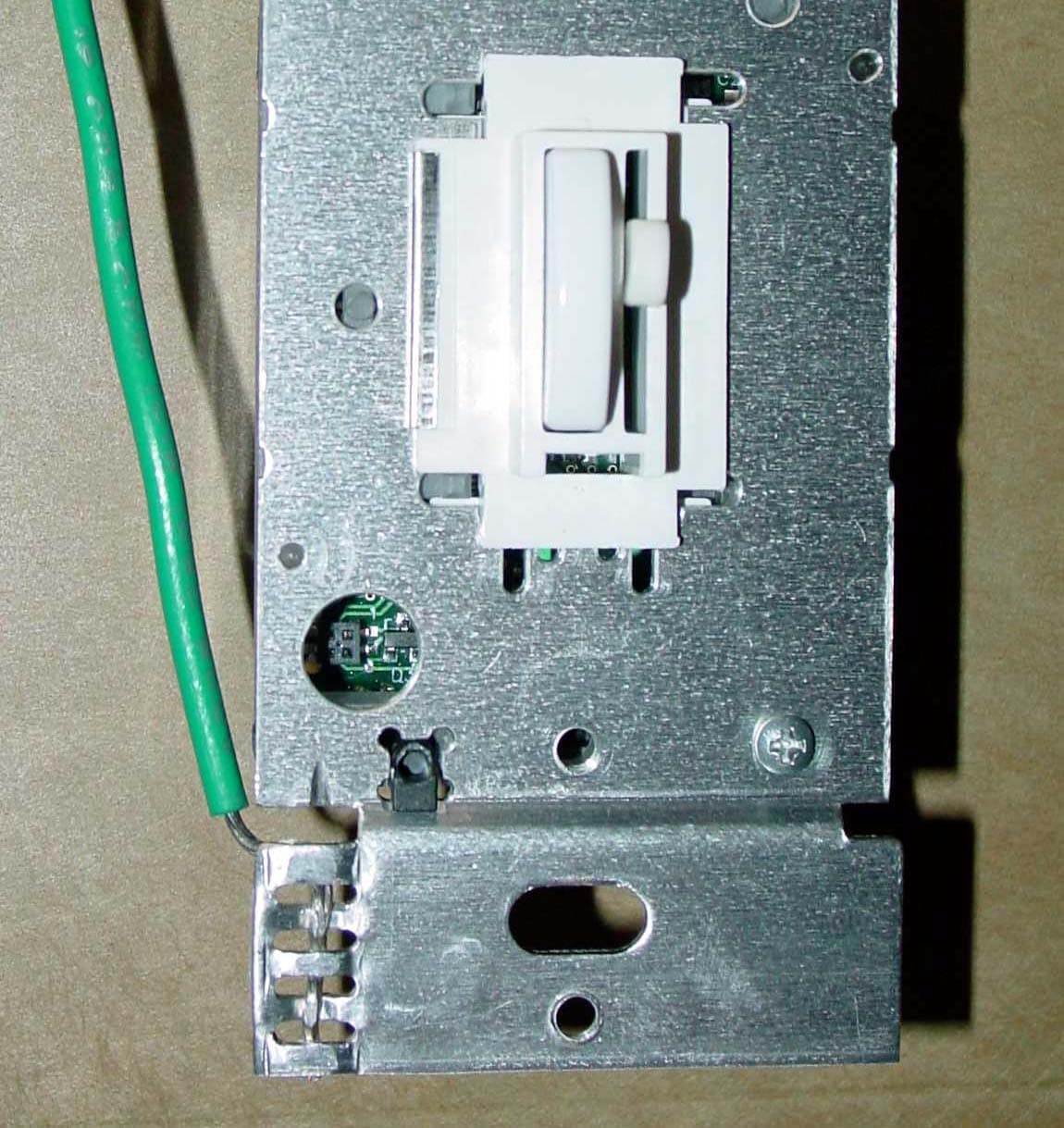
Click to zoom
Application Details
- Equipment Class
- DSC - Part 15 Security/Remote Control Transmitter
- Date of Grant
- Feb 13, 2006
- Application Purpose
- Original Equipment
- Date of Application
- Feb 13, 2006
- Equipment Note
- Tabletop Radio Frequency Key Pad Control
- Frequency Range
- 434.00000000 - 437.00000000
- Country
- United States
Documents & Files
Document Text
Text extracted from the exhibit documents filed with the FCC. Open a document above to read the original.
Users Manual
Lutron Electronics Co., Inc.7200 Suter RoadCoopersburg, PA 18036-1299, U.S.A.Made and printed in the U.S.A. 2 /06 P/N 044- 108 Rev. A FCC InformationNote: This equipment has been tested and found to comply with the limits for a Class B digital device, pursuant to Part 15 of the FCC rules. These limits aredesigned to provide reasonable protection against harmful interference in a res-idential installation. This equipment generates, uses and can radiate radio fre-quency energy and, if not installed and used in accordance with the instruc-tions, may cause harmful interference to radio or television reception. However,there is no guarantee that interference will not occur in a particular installation.If this equipment does cause harmful interference to radio or television recep-tion, which can be determined by turning the equipment off and on, the user isencouraged to try to correct the interference by one or more of the followingmeasures: • Reorient or relocate the receiving antenna.• Increase the seperation between the equipment and receiver.• Connect the equipment into an outlet on a circuit different from that to which the receiver is connected. • Consult the dealer or an experienced radio/TV technician for help. Caution: Changes or modifications not expressly approved by LutronElectronics Co. could void the user’s authority to operate this equipment.Operation is subject to the following: (1) This device may not cause harmfulinterference, and (2) this device must accept any interference received, including interference that may cause undesired operation. Limited Warranty(Valid only in the U.S., Canada, Puerto Rico, and the Caribbean.)Lutron will, at its option, repair or replace any unit that is defective in materialsor manufacture within one year after purchase. For warranty service, return unitto place of purchase or mail to Lutron at 7200 Suter Rd., Coopersburg, PA18036-1299, postage pre-paid .THIS WARRANTY IS IN LIEU OF ALL OTHER EXPRESS WARRANTIES,AND THE IMPLIED WARRANTY OF MERCHANTABILITY IS LIMITED TOONE YEAR FROM PURCHASE. THIS WARRANTY DOES NOT COVER THECOST OF INSTALLATION, REMOVAL OR REINSTALLATION, OR DAMAGERESULTING FROM MISUSE, ABUSE, OR IMPROPER OR INCORRECTREPAIR, OR DAMAGE FROM IMPROPER WIRING OR INSTALLATION.THIS WARRANTY DOES NOT COVER INOPERABILITY RESULTING FROMINTERFERENCE, INCORRECT INSTALLATION, OR ENVIRONMENTALFACTORS. THIS WARRANTY DOES NOT COVER INCIDENTAL OR CONSE-QUENTIAL DAMAGES. LUTRON’S LIABILITY ON ANY CLAIM FOR DAM-AGES ARISING OUT OF OR IN CONNECTION WITH THE MANUFACTURE,SALE, INSTALLATION, DELIVERY, OR USE OF THE UNIT SHALL NEVEREXCEED THE PURCHASE PRICE OF THE UNIT.This warranty gives you specific legal rights, and you may also have other rightswhich vary from state to state. Some states do not allow limitations on how longan implied warranty lasts, so the above limitation may not apply to you. Somestates do not allow the exclusion or limitation of incidental or consequentialdamages, so the above limitation or exclusion may not apply to you.These products may be covered under one or more of the following U.S.patents: 4,835,343; 4,954,768; 5,248,919; 5,399,940; 5,637,930; 5,736,965;5,798,581; 5,838,226; 5,848,054; 5,905,442; 5,982,103; 6,687,487; D353,798and corresponding foreign patents. U.S. and foreign patents pending. Lutron, Fassada, and the sunburst logo are registered trademarks and AuroRAis a trademark of Lutron Electronics Co., Inc.© 200 6 Lutron Electronics Co., Inc. Technical AssistanceIf you have questions concerning the installation or opera-tion of this product, call the Lutron Technical Support Center. Please provide exact model number when calling. +1.800.523.9466 (U.S.A., Canada, and the Caribbean)Other countries call +1.610.282.3800Fax +1.610.282.3090Visit our web site at www.lutron.com Important Notes 11. . Caution :: To avoid overheating and possible damage to other equipment, do not use dimmers to control recep-tacles, fluorescent lighting fixtures, motor-operated ortransformer-supplied appliances. 22. . Use dimmers with 120V incandescent lighting fixturesonly. Do not use with low-voltage transformers. 33. . Install in accordance with all national and local electricalcodes. 44. . When there is no ground wire or a way to connect thewallbox to ground within the wallbox then the NEC ® 2002, Article 404-9 allows a dimmer without a ground-ing connection to be installed as a replacement, as longas a plastic, noncombustible wallplate is used. For thistype of installation, cap or remove the green groundwire on the dimmer and use an appropriate wallplatesuch as Lutron’s Fassada ® series wallplates. 55. . Do not paint dimmers or wallplates. 66. . The total wattage of all light bulbs controlled by eachdimmer must be between 50 and 600 watts. 77. . Dimmers work with most incandescent light bulbs.Dimmers may not work with dioded light bulbs (SylvaniaCAPSYLITE DESIGNER 16 TM or Philips PAR-16 TM ). 88. . Operate system in temperatures between 0 °C (32 °F) and 40 °C (104 °F). 99. . Dimmer may feel warm to the touch during normaloperation. 110 0. . Recommended wallbox depth is 2 1/2" minimum. 111 1. . single-pole circuit three-way circuit four-way circuit 112 2. . When combining dimmers in the same wallbox, thedimmer’s load capacity must be reduced. 113 3. . Wire PreparationTrim or strip wallbox wires to the lengthindicated by the strip gauge on the backof the dimmer. Push-in: Insert wires fully. Use #14 AWGsolid copper wire only. For aluminumwire, consult an electrician. DO NOT usestranded or twisted wire.Screw Terminals: Tighten securely. Screwterminals are for use with solid copperwire only. For aluminum wire, consult anelectrician. DO NOT use stranded or twisted wire. 114 4. . Service SwitchPull service switch out to open position to replace lightbulbs. Push service switch in after new bulb isinstalled. Installation Instructions forReplacement Dimmer Read all instructions completely before installation. Incandescent / 120 V HalogenDimmerAR-6D…
Text truncated - open the document above for the full version.
External Photos
External photos December 2005 JPZ0038 Lutron: AR-6D Page 1 of 2 F 1112 I 1113 External photos December 2005 JPZ0038 Lutron: AR-6D Page 2 of 2
Internal Photos
Internal photos December 2005 JPZ0038 Lutron: AR-6D Page 1 of 2 F 1112 I 1113 Internal photos December 2005 JPZ0038 Lutron: AR-6D Page 2 of 2 F 1112 I 1113
Test Report
RADIATION SCIENCES INC. 1986.01 TEST REPORT NO. RSI-2828E ELECTROMAGNETIC EMISSION EVALUATION OF THE LUTRON ELECTRONICS MODEL #: AR-6D-yy FCC PART 15, SUBPART B AND C 24 JANUARY 2006 PREPARED FOR: Lutron Electronics 7200 Suter Road Coopersburg, PA 18036 SUBMITTED BY: Radiation Sciences Inc. 3131 Detwiler Road Harleysville, PA 19438 PREPARED BY: ____________________ Cathy J. Lattieri Q. A. Administration Radiation Sciences Inc. REVIEWED BY: ____________________ John Kavalusky EMC Test Engineer Radiation Sciences Inc. RADIATION SCIENCES INC. RSI-2828E i TABLE OF CONTENTS SECTION TITLE PAGE Table of Contents i List of Figures ii Administrative Data iii Summary of Test Results iv 1.0 INTRODUCTION 1 2.0 DESCRIPTION OF THE EQUIPMENT UNDER TEST (EUT) 2 3.0 TEST INSTRUMENTATION 3 4.0 TEST RESULTS 4 4.1 Conducted Emissions Test Results 4 4.2 Radiated Emissions Test Results 11 4.3 Bandwidth Measurements 25 5.0 Conclusions 30 RADIATION SCIENCES INC. RSI-2828E ii LIST OF FIGURES FIGURE TITLE PAGE FIGURE 1 Conducted Emissions Test Setup Diagram 5 FIGURE 2 Conducted Emissions Test Setup Photographs 6 FIGURE 3 Conducted Emissions Test Results Phase Line, Rx434MHz 7 FIGURE 4 Conducted Emissions Test Results Neutral Line, Rx434MHz 8 FIGURE 5 Conducted Emissions Test Results Phase Line, Rx437MHz 9 FIGURE 6 Conducted Emissions Test Results Neutral Line, Rx437MHz 10 FIGURE 7 Duty Cycle Correction Factor 12 FIGURE 8 Radiated Emissions Test Setup Diagram 13 FIGURE 9 Radiated Emissions Test Setup Photographs 14 FIGURE 10 Radiated Emissions Test Results Data, Rx, Mode, 434MHz 15 FIGURE 11 Radiated Emissions Test Results Graph, Rx, Mode, 434MHz 16 FIGURE 12 Radiated Emissions Test Results Data, Rx, Mode, 437MHz 17 FIGURE 13 Radiated Emissions Test Results Graph, Rx, Mode, 437MHz 18 FIGURE 14 Radiated Emissions Test Results Data, CW, Tx Mode, 434MHz, Vert. 19 FIGURE 15 Radiated Emissions Test Results Data, CW, Tx Mode, 434MHz, Horiz. 20 FIGURE 16 Radiated Emissions Test Results Data, CW, Tx Mode, 437MHz, Vert. 21 FIGURE 17 Radiated Emissions Test Results Data, CW, Tx Mode, 437MHz, Horiz. 22 FIGURE 18 Intentional Radiator Test Results Data, CW, Tx Mode, 434MHz, H & V 23 FIGURE 19 Intentional Radiator Test Results Data, CW, Tx Mode, 437MHz, H & V 24 FIGURE 20 Bandwidth Test Results Data, CW, Tx Mode, 434MHz 26 FIGURE 21 Bandwidth Test Results Waveform, CW, Tx Mode, 434MHz 27 FIGURE 22 Bandwidth Test Results Data, CW, Tx Mode, 437MHz 28 FIGURE 23 Bandwidth Test Results Waveform, CW, Tx Mode, 437MHz 29 RADIATION SCIENCES INC. RSI-2828E iii ADMINISTRATIVE DATA TEST PERFORMED: Measurements of Radiated and Conducted Emissions. PURPOSE OF TEST: To evaluate the ElectroMagnetic Emission (EME) characteristics of the Equipment Under Test (EUT) with respect to Subpart B and C of Part 15 of the Federal Communications Commission (FCC) Rules for intentional and unintentional radiators. EQUIPMENT UNDER TEST (EUT): Model Number: AR-6D-yy Serial Number: NSN CONTRACT: Purchase Order Number: 0047112 TEST PERIOD: 15 November through 20 December 2005 and 13 January 2006 TEST FACILITY: Radiation Sciences Incorporated (RSI), EMC Test Laboratory, located at: 3131 Detwiler Road, Harleysville, Pennsylvania 19438. TEST PERSONNEL AND COORDINATORS : Radiation Sciences Inc. Lutron Electronics John Kavalusky Mark Clouser Robert Bollinger RADIATION SCIENCES INC. RSI-2828E iv SUMMARY OF TEST RESULTS The Model #: AR-6D-yy, configured as described herein, FULLY COMPLIES WITH THE REQUIREMENTS SET FORTH IN SUBPART B AND C OF PART 15 OF THE FED- ERAL COMMUNICATIONS COMMISSION (FCC) RULES FOR INTENTIONAL AND UNINTENTIONAL RADIATORS. The test results contained in this report represent emission and/or immunity characteristics of only the product(s) (model and serial no.) tested. Radiation Sciences Inc. makes no claim that identical test results will be obtained for future tests of the same model/equipment. RADIATION SCIENCES INC. RSI-2828E 1 1.0 INTRODUCTION This document is a report of tests to determine the EME characteristics of the Model #: AR-6D- yy, presented by Lutron Electronics of Coopersburg, Pennsylvania. The purpose of the testing was to evaluate the EMC characteristics of the test sample with re- spect to Subpart B and C of Part 15 of the FCC Rules for intentional and unintentional radiators. All test procedures used meet the requirements of the American National Standards Institute Procedure C63:4: "Methods of Measurement of Radio-Noise Emissions from Low-Voltage Electrical and Electronic Equipment in the Range of 9kHz to 40GHz", 2003. RADIATION SCIENCES INC. RSI-2828E 2 2.0 DESCRIPTION OF THE TEST SAMPLE: The Model # AR-6D-yy, manufactured by Lutron Electronics of Coopersburg PA, is a Wall mounted radio controlled lamp dimmer. The –yy stands for the color code. Hereinafter, the Model #AR-6D-yy, will be referred to as the EUT (Equipment Under Test). RADIATION SCIENCES INC. RSI-2828E 3 3.0 TEST INSTRUMENTATION RSI CAL INV DUE NO. DESCRIPTION MANUFACTURER MODEL # SERIAL # DATE 31 SPEC ANALYZER ADVANTEST R3271 J003583 1/27/2006 32.1 SPEC. ANALY. H.P. 8566B 3638A08767 8/13/2006 33.1 SPEC. ANALY. DISPLY H.P. 3701A22258 8/13/2006 39 PRE-AMP H.P. 8349A 2403A00298 4/05/2006 52 ANTENNA EMCO 3115 2425 6/10/2007 75 ANTENNA TENSOR 4108 204 6/11/2007 80 ANTENNA AMP.RES.Assoc. AT1000 4094-025 6/14/2007 391 RECEIVER R & S ESVP 861744/015 3/15/2006 501 MINI MAST EMCO 2075-2 0002-2278 502 TURNTABLE EMCO 2065-1.21 0001-2156 503 CONTROLLER EMCO 2090 0001-1489 708 40ft Cable RG-223 PASTERNACK BNC TO BNC N/A 10/26/2006 712 20ft Cable RG-223 PASTERNACK BNC TO BNC N/A 10/26/2006 717 10ft SMA Cable MIRO COAX(blue) SMA TO SMA N/A 9/15/2006 IF CAL DUE DATE = BLANK FIELD Calibration is not required for this item. Equipment not used to obtain a final reading (i.e. transmitting antenna). RADIATION SCIENCES INC. RSI-2828E 4 4.0 TEST RESULTS 4.1 Conducted Power Line Measurements, Paragraph 15.107 Conducted power line measurements were recorded for the EUT. The EUT was pla…
Text truncated - open the document above for the full version.
Test Setup Photos
Biconical antenna freq. 30-200MHz Log-Periodic Freq. 200-1000MHz 3115 Double Ridge wave Guide 1-18GHz EUT test configuration Radiated Emissions Test Setup Photographs Figure
Contact Information
Applicant
Daniel Schlegel(Standards Compliance Supervisor)
Test Firm
Radiation Sciences Inc.Daniel Signore
Technical Specifications
| # | Rule Parts | Frequency Range | Power Output | Emission | Tolerance |
|---|---|---|---|---|---|
| 1 | 15.231 | 434 MHz - 437 MHz | 1.80 µW | F7D | 0.2500000000 % |
Other Applications from Lutron Electronics Company Inc
JPZ0161
Sep 03, 2026Wireless Interface
Equipment Class
DTS - Digital Transmission SystemJPZ0159
Aug 12, 2026Wireless Processor
Equipment Class
DTS - Digital Transmission SystemJPZ0158
Jul 27, 2026Copy of Wireless Processor
Equipment Class
DTS - Digital Transmission SystemJPZ0157
Mar 26, 2026LED Downlight
Equipment Class
DTS - Digital Transmission SystemJPZ0155
Sep 30, 2024LED Lighting Controller
Equipment Class
DTS - Digital Transmission System