JPZ0068RF Daylight Sensor
Lutron Electronics Company Inc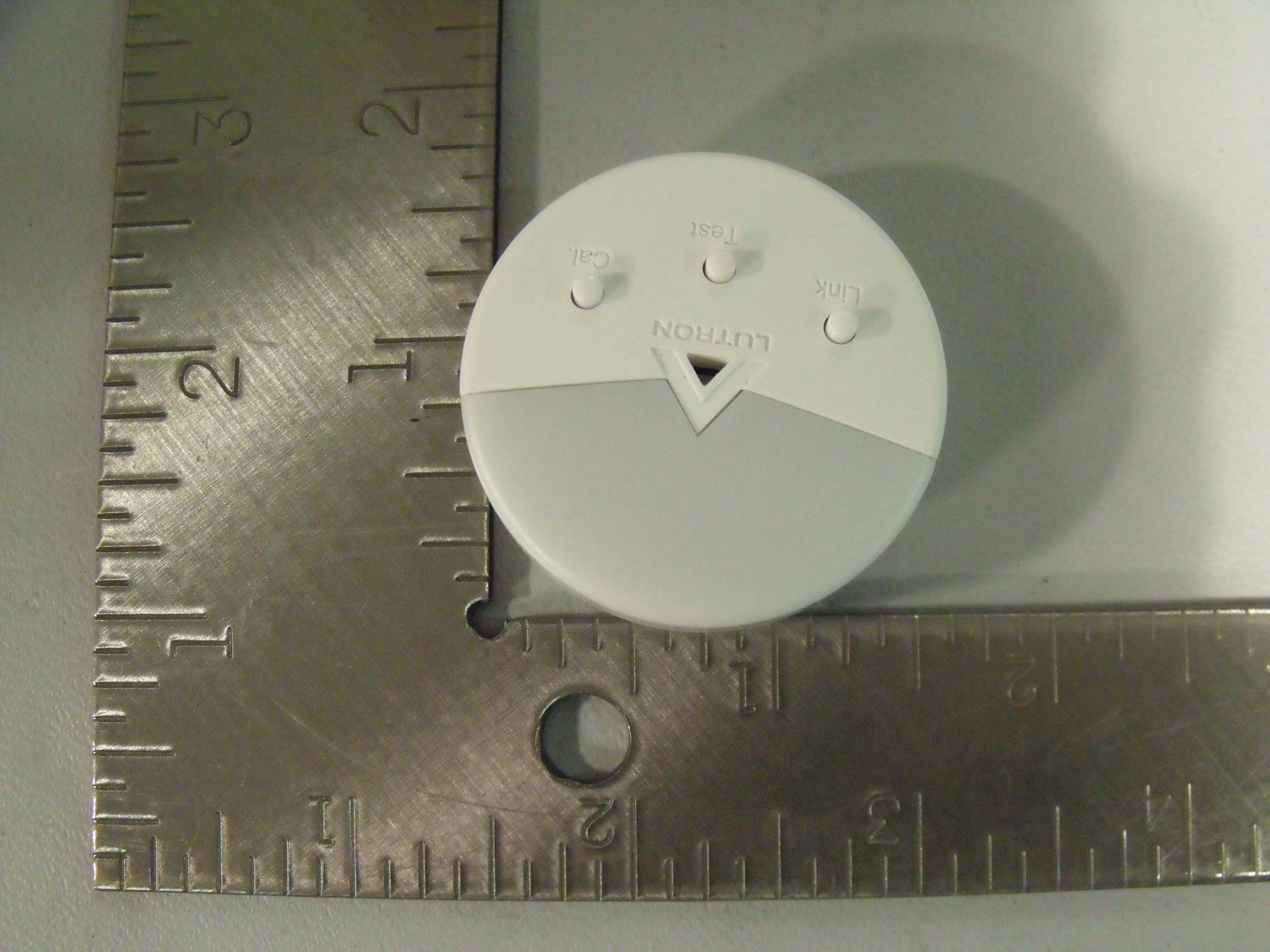
Click to zoom
Application Details
- Equipment Class
- DXX - Part 15 Low Power Communication Device Transmitter
- Date of Grant
- Jan 12, 2010
- Application Purpose
- Original Equipment
- Date of Application
- Jan 12, 2010
- Equipment Note
- RF Daylight Sensor
- Frequency Range
- 431.00000000 - 437.00000000
- Country
- United States
Documents & Files
Document Text
Text extracted from the exhibit documents filed with the FCC. Open a document above to read the original.
Users Manual
1 2 3 4 5 6 To remove the bracket from the ceiling, grasp the removal tab on the adhesive strip and pull the tab VERY SLOWLY straight across the ceiling, stretching the strip until the bracket releases from the ceiling. Discard the strip. NEVER pull the strip at an angle, as it may break or damage the ceiling surface. Identify a location for the Sensor (see section C. Sensor Placement). Remove the black “wall side” liner from the adhesive strip. Position the mounting bracket on the ceiling and press firmly for several seconds. Attach the Sensor to the mounting bracket. Perform the Calibration and Test the Sensor as described in section E. Calibration and F. Testing the Daylight Sensor. If the Sensor does not perform satisfactorily from this location, it may be moved to another location by pulling the Sensor straight down and repeating steps 2.1 – 2.7. If the Sensor’s performance is satisfactory, it should be permanently attached to the ceiling tile, as described in section H. Permanent Mounting Methods. Testing the Daylight Sensor Before testing, ensure power to the lighting circuit is ON and the lighting control system is setup and calibrated properly. The lighting circuit should be energized only when all wiring is complete and all persons are clear of fixtures/devices. Turn power ON only after checking that it is safe to do so. Activate Test mode by pressing the “Test” button on the front of the Sensor. The lens will flash indicating that the mode was entered. Select all Dimmers or Electronic Switches that you want to test by pressing the tap button. Cover the Sensor – the system should increase/switch on the lights in the room Shine light on the Sensor – the system should decrease/switch off the lights in the room With the lights on, do nothing to the Sensor – If the lights in the room cycle on and off, there is too much feedback from the lights – consider moving Sensor away from lights or re-calibrate the system (see section E. Calibration). Exit Test mode by pressing the “Test” button again. Sensor Placement Determine the Daylight Sensor Mounting Location using the diagrams below: • The arrow on the daylight sensor points toward the area viewed by the sensor. • Place the daylight sensor so its viewing area is centered on the nearest window at a distance from the window of one and two times the effective window height (H). • The effective window height (H) starts at the window sill or 3 ft (1 m) up from the floor, whichever is higher, and ends at the top of the window. • Ensure that the view of the daylight sensor is not obstructed. • Do not position the daylight sensor in the well of a skylight or above indirect lighting fixtures. • For narrow areas where the daylight sensor cannot be placed 1-2 (H) from windows, place sensor near windows facing into the space. Temporary Mounting Methods If you are uncertain about correctly positioning the Sensor, the following temporary mounting and testing procedures are recommended to verify proper performance before permanently installing the Sensor. Temporary Drop Ceiling Mounting Use this procedure if the Sensor will be mounted on a ceiling tile. The ceiling tile mounting wire is provided for both temporary and permanent mounting of the Sensor to drop ceilings composed of multiple tiles. It is designed to allow temporary mounting, testing, and repositioning (if necessary) of the Sensor without damaging a ceiling tile. Once the Sensor’s final position has been chosen, the mounting wire can be twisted to lock the Sensor in place permanently. Remove the mounting bracket from the base of the Sensor. Insert the ceiling tile mounting wire through the two smaller holes in the mounting bracket and replace the mounting bracket. Mount Sensor to a ceiling tile by inserting the wire legs through the tile making sure the Sensor is flush to the tile. Perform the Calibration and Test the Sensor as described in sections E. Calibration and F. Testing the Daylight Sensor. If the Sensor does not perform satisfactorily from this location, it may be moved to another location by pulling the Sensor straight down and repeating steps 1.3 and 1.4. If the Sensor’s performance is satisfactory, it should be permanently attached to the ceiling tile, as described in section H. Permanent Mounting Methods. A Installation The Sensor installation procedure is outlined below. Please follow these steps to ensure the Sensor will perform as intended: A. Pre-Installation F. Testing the Daylight Sensor B. Set-Up G. Tuning the System C. Sensor Placement and Coverage H. Permanent Mounting Methods D. Temporary Mounting Methods E. Calibration Pre-Installation Before setting up the Sensor, the corresponding dimming or switching device(s) should be installed. Refer to that product’s installation sheet for instructions. Pull and remove mounting bracket to insert battery with the negative (–) side up. Set-Up In order for the Sensor to operate properly, it must first be set up with a corresponding dimming or switching device. The procedure for setting up a Sensor with a Maestro Wireless ® (MRF2- only) Dimmer or Electronic Switch is detailed below. If setting up a Sensor with a different device, visit www.lutron.com/occsensors or consult the installation guide for that device for the correct set-up procedure. Setting up a Sensor with a Maestro Wireless Dimmer or Electronic Switch Place the Dimmer or Electronic Switch in set-up mode by pressing and holding the tap button for approximately 6 seconds until all LEDs on the device begin flashing. Release the tap button. Add the Sensor to the Dimmer or Electronic Switch by pressing and holding the “Link” button on the front of the Sensor for approximately 6 seconds until the lens flashes briefly. The lights in the room will also flash 3 times, indicating the Sensor has been successfully added. The Dimmer or Electronic Switch will exit set-up mode automatically. C Key Features · Easy Installation. No wiring required. · Easy Set-Up. Default settings …
Text truncated - open the document above for the full version.
Block Diagram
Micro-controller (8MHz Clock, 1MHz Bus) SX1230 RF Transmitter 1MHz SPI 32MHz Crystal ButtonsLED's Loop Antenna 431MHz-437MHz fc Photo Detector 62.5KHz Data 1MHz CLK Out
Test Report
Underwriters Laboratories Inc. A not-for-profit organization dedicated 1285 Walt Whitman Rd. to public safety and committed to Melville, NY 11747 quality service for over 100 years Tel: (631) 271-6200 Fax: (631)439-6095 Underwriters Laboratories Inc. 1285 Walt Whitman Rd. Melville, NY 11747 www.ul.com/emc (631) 271-6200 Job Number: 1001188273 Project Number: 09CA60255 File Number: MC15896 Date: January 7, 2010 Model: LRF2-DCRB FCC ID: JPZ0068 IC Number: 2851A-JPZ0068 Electromagnetic Compatibility Test Report For LUTRON ELECTRONICS INC Copyright 2007 Underwriters Laboratories Inc. Underwriters Laboratories Inc. authorizes the above-named company to reproduce this Report provided it is reproduced in its entirety. Job Number: 1001188273 File Number: MC15896 Page 2 of 51 Model Number: LRF2-DCRB Client Name: LUTRON ELECTRONICS INC FCC ID:JPZ0068 IC Number:2851A-JPZ0068 Underwriters Laboratories Inc. 1285 Walt Whitman Rd. Melville, New York 11747 USA Tel.: 631 271-6200 Fax: 631 439-6095 Rev. No 1.0 EMC Report 2007 Test Report Details Tests Performed By: Underwriters Laboratories Inc. 1285 Walt Whitman Rd. Melville, NY 11747 Tests Performed For: LUTRON ELECTRONICS INC 7200 SUTTER ROAD COOPERBURG, PA 18036 Applicant Contact: BOB SPEHALSKI Contact Signature*: Title: Engineering Manager Phone: (610) 282-7424 E-mail: [email protected] Test Report Date: January 7, 2010 Product Type: Daylight Sensor Product standards FCC Part 15, Subpart C, 15.231 Model Number: LRF2-DCRB Sample Serial Number: Non-serialized production unit EUT Category: Periodic Low Power Transmitter Testing Start Date: 16 December 2009 Date Testing Complete: 17 December 2009 Overall Results: Compliant Underwriters Laboratories Inc. reports apply only to the specific samples tested under stated test conditions. All samples tested were in good operating condition throughout the entire test program. It is the manufacturer's responsibility to assure that additional production units of this model are manufactured with identical electrical and mechanical components. Underwriters Laboratories Inc. shall have no liability for any deductions, inferences or generalizations drawn by the client or others from Underwriters Laboratories Inc. issued reports. This report shall not be used to claim, constitute or imply product certification, approval, or endorsement by NVLAP, NIST, A2LA, or any agency of the US government. This report may contain test results that are not covered by the NVLAP or A2LA accreditation. The scope of accreditation is limited to the specific tests that are listed on the NVLAP and/or A2LA websites referenced at the end of this report. *Signature required for products covered by FCC Declaration of Conformity or Verification in accordance with record retention requirements in FCC Rules 2.955(x) or 2.1057(x). Job Number: 1001188273 File Number: MC15896 Page 3 of 51 Model Number: LRF2-DCRB Client Name: LUTRON ELECTRONICS INC FCC ID:JPZ0068 IC Number:2851A-JPZ0068 Underwriters Laboratories Inc. 1285 Walt Whitman Rd. Melville, New York 11747 USA Tel.: 631 271-6200 Fax: 631 439-6095 Rev. No 1.0 EMC Report 2007 Report Directory 1.0 G E N E R A L - Product Description ..................................................................................................................4 1.1 Equipment Description ...................................................................................................................................4 1.2 Equipment Marking Plate ...............................................................................................................................4 1.3 Device Configuration During Test ..................................................................................................................5 1.3.1 Equipment Used During Test: ....................................................................................................................5 1.3.2 Input/Output Ports: .....................................................................................................................................5 1.3.3 EUT Internal Operating Frequencies: ........................................................................................................6 1.3.4 Power Interface: .........................................................................................................................................6 1.4 Block Diagram: ...............................................................................................................................................7 1.5 EUT Configurations ........................................................................................................................................8 1.6 EUT Operation Modes ....................................................................................................................................8 2.0 Summary ............................................................................................................................................................9 2.1 Deviations from standard test methods ..........................................................................................................9 2.2 Device Modifications Necessary for Compliance ...........................................................................................9 2.3 Reference Standards .................................................................................................................................. 10 2.4 Results Summary ........................................................................................................................................ 10 3.0 Calibration of Equipment Used for Measurement ........................................................................................... 11 4.0 EMISSIONS TEST RESULTS ......................................................................................................................... 11 4.1 Test Conditions and Results – OCCUP…
Text truncated - open the document above for the full version.
Test Setup Photos
Job Number: 1001188273 File Number: MC15896 Page 13 of 51 Model Number: LRF2-DCRB Client Name: LUTRON ELECTRONICS INC FCC ID:JPZ0068 IC Number:2851A-JPZ0068 Underwriters Laboratories Inc. 1285 Walt Whitman Rd. Melville, New York 11747 USA Tel.: 631 271-6200 Fax: 631 439-6095 Rev. No 1.0 EMC Report 2007 Figure 1 Test Setup for Occupied Bandwidth Job Number: 1001188273 File Number: MC15896 Page 24 of 51 Model Number: LRF2-DCRB Client Name: LUTRON ELECTRONICS INC FCC ID:JPZ0068 IC Number:2851A-JPZ0068 Underwriters Laboratories Inc. 1285 Walt Whitman Rd. Melville, New York 11747 USA Tel.: 631 271-6200 Fax: 631 439-6095 Rev. No 1.0 EMC Report 2007 Figure 8 Test setup for Radiated Emissions
Contact Information
Applicant
Daniel Schlegel(Standards Compliance Supervisor)
Technical Contact
Lutron ElectronicsMatthew Cardoni
[email protected]610-282-3800
7200 Suter Rd · Coopersburg · United States
Non-Technical Contact
Lutron ElectronicsRobert Spehalski
[email protected]610-282-3800
Test Firm
UL LLCBob Delisi
Technical Specifications
| # | Rule Parts | Frequency Range | Power Output |
|---|---|---|---|
| 1 | 15C | 431 MHz - 437 MHz | - |
Other Applications from Lutron Electronics Company Inc
JPZ0161
Sep 03, 2026Wireless Interface
Equipment Class
DTS - Digital Transmission SystemJPZ0159
Aug 12, 2026Wireless Processor
Equipment Class
DTS - Digital Transmission SystemJPZ0158
Jul 27, 2026Copy of Wireless Processor
Equipment Class
DTS - Digital Transmission SystemJPZ0157
Mar 26, 2026LED Downlight
Equipment Class
DTS - Digital Transmission SystemJPZ0155
Sep 30, 2024LED Lighting Controller
Equipment Class
DTS - Digital Transmission System