JPZ0070Electronic control with RF communication
Lutron Electronics Company Inc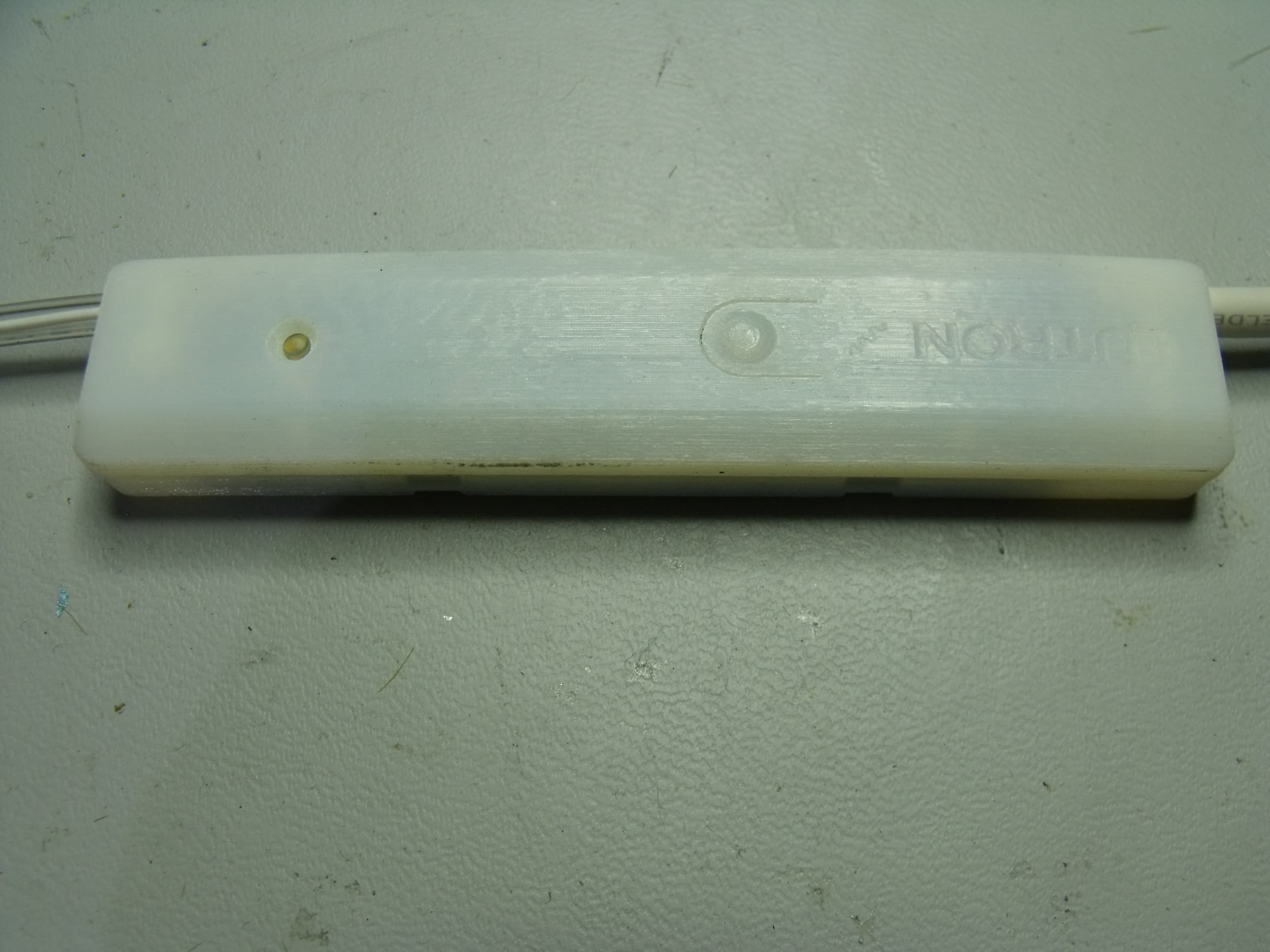
Click to zoom
Application Details
- Equipment Class
- DXT - Part 15 Low Power Transceiver, Rx Verified
- Date of Grant
- May 10, 2010
- Application Purpose
- Original Equipment
- Date of Application
- May 10, 2010
- Equipment Note
- Electronic control with RF communication
- Frequency Range
- 431.00000000 - 437.00000000
- Country
- United States
Documents & Files
Document Text
Text extracted from the exhibit documents filed with the FCC. Open a document above to read the original.
Users Manual
R Installation Instructions Occupant Copy Please Read SZ-CI-USB-CPN5138 USB Interface PELV (Class 2: USA) Device 5 V 60 mA StanzaTM Features • Integrates a Stanza guest room lighting control system with a PC or other digital equipment that supports USB devices. • Provides a basic serial string command set that allows a PC to monitor and control lighting. • Programmed and commissioned by a SZ-CI-PRG Programming Control Interface. • Should not be used in “Advanced” systems with a permanently installed SZ-CI-PRG. • Wireless connection allows easy mounting near integration device. Mounting 1. Secure the provided mounting clip to a flat, clean surface with the double-sided tape on the clip. Then secure the USB interface in the mounting clip. 2. Connect the provided USB cable from the device to the 3rd party equipment. 3. Use provided antenna clip and double-sided tape to securely mount the antenna. 4. Mount in an accessible location for convenient access to the programming button, LED, and USB cable. 5. The unit cannot be mounted in a full metal enclosure or between two metal surfaces. 6. When mounting, provide sufficient space for the antenna and USB cable. FCC Information Note: This equipment has been tested and found to comply with the limits for a Class B digital device, pursuant to Part 15 of the FCC rules. These limits are designed to provide reasonable protection against harmful interference in a residential installation. This equipment generates, uses, and can radiate radio frequency energy and, if not installed and used in accordance with the instructions, may cause harmful interference to radio or television reception. However, there is no guarantee that interference will not occur in a particular installation. If this equipment does cause harmful interference to radio or television reception, which can be determined by turning the equipment off and on, the user is encouraged to try to correct the interference by one or more of the following measures: • Reorient or relocate the receiving antenna. • Increase the separation between the equipment and receiver. • Connect the equipment into an outlet on a circuit different from that to which the receiver is connected. • Consult the dealer or an experienced radio/TV technician for help. Caution: Changes or modifications not expressly approved by Lutron Electronics Co. could void the user’s authority to operate this equipment. Operation is subject to the following: (1) This device may not cause harmful interference, and (2) this device must accept any interference received, including interference that may cause undesired operation. Dimensions Dimensions are in inches. 0.89 0.843 0.44 0.255 4.0 0.5 1.691 0.78 Antenna Clip Mounting Clip USB Mini-B Female Connector 31.5 FCC Information Changes or modifications not expressly approved by Lutron Electronics Co. could void the user’s authority to operate this equipment. NOTE: This equipment has been tested and found to comply with the limits for a Class B digital device, pursuant to Part 15 of the FCC rules. Operation is subject to the following: (1) This device may not cause harmul interference, and (2) this device must accept any interference received, including interference that may cause undesired operation. R Lutron Electronics Co., Inc. Made and printed in U.S.A. P/N 040-361 Rev. A 04.21.10 Internet: www.lutron.com/stanza e-mail: [email protected] Technical support: USA, Canada, Caribbean: 1.800.523.9466 Mexico: +1.888.235.2910 Central/South America: +1.610.282.6701 Warranty: 1-year limited warranty standard. 2-year parts and labor warranty, with 8-year pro-rated parts replacement on systems that include factory startup. For complete warranty details, see the Start-Up/Warranty document provided with your Stanza system specification submittal information. Lutron and the sunburst logo are registered trademarks and Stanza is a trademark of Lutron Electronics Co., Inc. © 2010 Lutron Electronics Co., Inc. Mounting Clip Device Operation USB Mini-B Female Connector LED Off during normal operation (unless TX / RX monitoring is enabled). Flashes Orange during programming mode. Button Used during device programming for association to Stanza system. Troubleshooting SymptomCause and Action Device does not address to system.Device not powered • Connecting equipment is not powered • USB port on connecting equipment not powered Device out of RF range • Ensure device is within 30 ft (9 m) of StanzaTM device configured as a repeater Device is programmed to another system • Contact Lutron Technical Support for details on how to factory default the device COM port cannot be established with device Device not powered • Connecting equipment is not powered • USB port on connecting equipment not powered Virtual COM port is set up incorrectly • See the Lutron Integration Protocol guide for proper COM port settings Device does not respond to integration commands Virtual COM port is set up incorrectly • See the Lutron Integration Protocol guide for proper COM port settings Device is not programmed to system • Ensure device was addressed to an existing Stanza system Incorrect integration commands • Ensure that the proper commands and integration IDs are being used StanzaTM system devices do not respond to issued integration commands Device out of RF range • Ensure device is within 30 ft (9 m) of Stanza device configured as a repeater Incorrect integration commands • Ensure that the proper commands and integration IDs are being used Device does not monitor system changesVirtual COM port is set up incorrectly • See the Lutron Integration Protocol guide for proper COM port settings Device is not programmed to system • Ensure device was addressed to an existing Stanza system Device out of RF range • Ensure device is within 30 ft (9 m) of Stanza device configured as a repeater Monitoring disabled • See the Lutron Integration Protocol guide for disabling/enabling monitoring
Block Diagram
JPZ0070 SZ-CI-USB Page 1 of 1 Block Diagram 23 April 2010 16 M hz 66 M hz 26 Mhz 5Vdc +2.8 +v +v +v +v F 961 I 831
Test Report
Underwriters Laboratories Inc. A not-for-profit organization dedicated 1285 Walt Whitman Rd. to public safety and committed to Melville, NY 11747 quality service for over 100 years Tel: (631) 271-6200 Fax: (631)439-6095 Underwriters Laboratories Inc. 1285 Walt Whitman Rd. Melville, NY 11747 www.ul.com/emc (631) 271-6200 Job Number: 1001228033 Project Number: 10CA18152 File Number: MC15832 Date: 28 April 2010 Model: SZ-CI-USB FCC ID: JPZ0070 IC Number: 2851A-JPZ0070 Electromagnetic Compatibility Test Report For LUTRON ELECTRONICS INC Copyright 2007 Underwriters Laboratories Inc. Underwriters Laboratories Inc. authorizes the above-named company to reproduce this Report provided it is reproduced in its entirety. Job Number: 1001228033 File Number: MC15832 Page 2 of 73 Model Number: SZ-CI-USB Client Name: LUTRON ELECTRONICS INC FCC ID: JPZ0070 IC Number: 2851A-JPZ0070 Underwriters Laboratories Inc. 1285 Walt Whitman Rd. Melville, New York 11747 USA Tel.: 631 271-6200 Fax: 631 439-6095 Rev. No 1.0 EMC Report 2007 Test Report Details Tests Performed By: Underwriters Laboratories Inc. 1285 Walt Whitman Rd. Melville, NY 11747 Tests Performed For: LUTRON ELECTRONICS INC 7200 SUTTER ROAD COOPERBURG, PA 18036 Applicant Contact: Dan Mitchell Phone: 610-282-5370 E-mail: [email protected] Test Report Date: 28 April 2010 Product Type: Low Power Transceiver Product standards FCC Part 15, Subpart C, 15.231 Model Number: SZ-CI-USB Sample Serial Number: Non-serialized Production Unit EUT Category: Periodic Low Power Transmitter Testing Start Date: 08 April 2010 Date Testing Complete: 12 April 2010 Overall Results: Compliant Underwriters Laboratories Inc. reports apply only to the specific samples tested under stated test conditions. All samples tested were in good operating condition throughout the entire test program. It is the manufacturer's responsibility to assure that additional production units of this model are manufactured with identical electrical and mechanical components. Underwriters Laboratories Inc. shall have no liability for any deductions, inferences or generalizations drawn by the client or others from Underwriters Laboratories Inc. issued reports. This report shall not be used to claim, constitute or imply product certification, approval, or endorsement by NVLAP, NIST, A2LA, or any agency of the US government. This report may contain test results that are not covered by the NVLAP or A2LA accreditation. The scope of accreditation is limited to the specific tests that are listed on the NVLAP and/or A2LA websites referenced at the end of this report. Job Number: 1001228033 File Number: MC15832 Page 3 of 73 Model Number: SZ-CI-USB Client Name: LUTRON ELECTRONICS INC FCC ID: JPZ0070 IC Number: 2851A-JPZ0070 Underwriters Laboratories Inc. 1285 Walt Whitman Rd. Melville, New York 11747 USA Tel.: 631 271-6200 Fax: 631 439-6095 Rev. No 1.0 EMC Report 2007 Report Directory 1.0 G E N E R A L - Product Description ..................................................................................................................4 1.1 Equipment Description ...................................................................................................................................4 1.2 Equipment Marking Plate ...............................................................................................................................4 1.3 Device Configuration During Test ..................................................................................................................5 1.3.1 Equipment Used During Test: ....................................................................................................................5 1.3.2 Input/Output Ports: .....................................................................................................................................5 1.3.3 EUT Internal Operating Frequencies: ........................................................................................................6 1.3.4 Power Interface: .........................................................................................................................................6 1.4 Block Diagram: ...............................................................................................................................................7 1.5 EUT Configurations ........................................................................................................................................8 1.6 EUT Operation Modes ....................................................................................................................................8 2.0 Summary ............................................................................................................................................................9 2.1 Deviations from standard test methods ..........................................................................................................9 2.2 Device Modifications Necessary for Compliance ...........................................................................................9 2.3 Reference Standards .................................................................................................................................. 10 2.4 Results Summary ........................................................................................................................................ 10 3.0 Calibration of Equipment Used for Measurement ........................................................................................... 11 4.0 EMISSIONS TEST RESULTS ......................................................................................................................... 11 4.1 Test Conditions and Results – MAINS TERMINAL – CONDUCTED EMISSIONS .................................... 12 4.2 Test Conditions and Results – Occupied Bandwidth .................................................................................. 25 4.3 Test Condit…
Text truncated - open the document above for the full version.
Test Setup Photos
Job Number: 1001228033 File Number: MC15832 Page 14 of 73 Model Number: SZ-CI-USB Client Name: LUTRON ELECTRONICS INC FCC ID: JPZ0070 IC Number: 2851A-JPZ0070 Underwriters Laboratories Inc. 1285 Walt Whitman Rd. Melville, New York 11747 USA Tel.: 631 271-6200 Fax: 631 439-6095 Rev. No 1.0 EMC Report 2007 Figure 1 Test Setup for Conducted Emissions Job Number: 1001228033 File Number: MC15832 Page 26 of 73 Model Number: SZ-CI-USB Client Name: LUTRON ELECTRONICS INC FCC ID: JPZ0070 IC Number: 2851A-JPZ0070 Underwriters Laboratories Inc. 1285 Walt Whitman Rd. Melville, New York 11747 USA Tel.: 631 271-6200 Fax: 631 439-6095 Rev. No 1.0 EMC Report 2007 Figure 6 Test Setup for Occupied Bandwidth Job Number: 1001228033 File Number: MC15832 Page 37 of 73 Model Number: SZ-CI-USB Client Name: LUTRON ELECTRONICS INC FCC ID: JPZ0070 IC Number: 2851A-JPZ0070 Underwriters Laboratories Inc. 1285 Walt Whitman Rd. Melville, New York 11747 USA Tel.: 631 271-6200 Fax: 631 439-6095 Rev. No 1.0 EMC Report 2007 Figure 13 Test setup for Radiated Emissions
Contact Information
Applicant
Daniel Schlegel(Standards Compliance Supervisor)
Technical Contact
Lutron Electronics CoDaniel Mitchell
[email protected]610-282-5370
7200 Suter Rd · Coopersburg, Pennsylvania · United States
Non-Technical Contact
Lutron Electronics CoBob Spehalski
[email protected]610-282-7424
Test Firm
UL LLCBob Delisi
Technical Specifications
| # | Rule Parts | Frequency Range | Power Output |
|---|---|---|---|
| 1 | 15C | 431 MHz - 437 MHz | - |
Other Applications from Lutron Electronics Company Inc
JPZ0161
Sep 03, 2026Wireless Interface
Equipment Class
DTS - Digital Transmission SystemJPZ0159
Aug 12, 2026Wireless Processor
Equipment Class
DTS - Digital Transmission SystemJPZ0158
Jul 27, 2026Copy of Wireless Processor
Equipment Class
DTS - Digital Transmission SystemJPZ0157
Mar 26, 2026LED Downlight
Equipment Class
DTS - Digital Transmission SystemJPZ0155
Sep 30, 2024LED Lighting Controller
Equipment Class
DTS - Digital Transmission System