JPZ0071Hybrid Keypad
Lutron Electronics Company Inc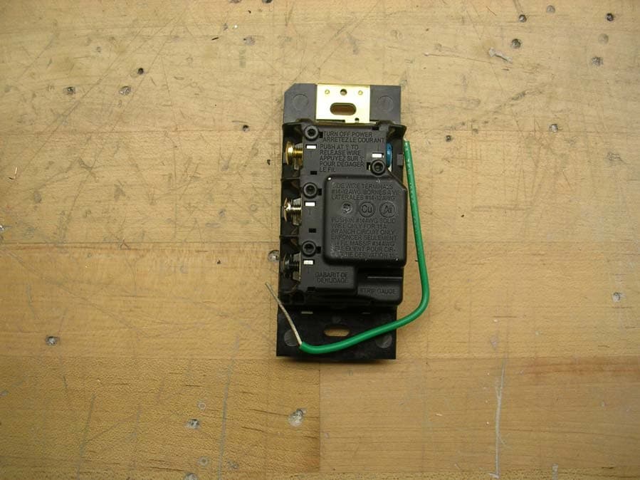
Click to zoom
Application Details
- Equipment Class
- DXT - Part 15 Low Power Transceiver, Rx Verified
- Date of Grant
- May 13, 2010
- Application Purpose
- Original Equipment
- Date of Application
- May 13, 2010
- Equipment Note
- Hybrid Keypad
- Frequency Range
- 431.00000000 - 437.00000000
- Country
- United States
Documents & Files
Document Text
Text extracted from the exhibit documents filed with the FCC. Open a document above to read the original.
Users Manual
Multi-Location Installation without Neutral 2, 3 Brass Black Blue Green Ground Lighting Load Hybrid Keypad or Remote Dimmer Brass Black Blue Green Ground Remote Dimmer or Hybrid Keypad 120 V 50 / 60 Hz Brass Black Blue Green Ground Hot/Live Neutral Remote Dimmer or Hybrid Keypad Silver Multi-Location Installation with Neutral 3, 4 Brass Silver Black Blue Green Ground Brass Black Blue Green Ground Remote Dimmer 120 V 50 / 60 Hz Brass Black Blue Green Ground Hot/Live Neutral Remote Dimmer Hybrid Keypad Wiring Diagram 1b Lighting Load Single Location Installation without Neutral 1, 2 Wiring Diagram 2a Brass Black Blue 1 Green Ground Hot/Live Neutral Lighting Load Hybrid Keypad 120 V 50 / 60 Hz Silver Single Location Installation with Neutral 1 Wiring Diagram 1a 120 V 50 / 60 Hz Brass Silver Black Blue 1 Green Ground Hot/Live Neutral Hybrid Keypad Lighting Load Load Specifications: 1 Load Type: Hybrid Keypads are designed for use with permanently installed incandescent, magnetic low-voltage, or tungsten halogen only. To reduce the risk of overheating and possible damage to other equipment, do not install Hybrid Keypads to control receptacles or motor-operated appliances. 2 Low-Voltage Applications: Use Hybrid Keypads with magnetic (core and coil) low-voltage transformers only. Not for use with electronic (solid-state) low-voltage transformers. Operation of a low-voltage circuit with lamps inoperative or removed may result in transformer overheating and premature failure. Lutron strongly recommends the following: • Do not operate low-voltage circuits without operative lamps in place. • Replace burned-out lamps as quickly as possible. • Use transformers that incorporate thermal protection or fused transformer primary windings to prevent transformer failure due to overcurrent. Important Notes WARNING - Entrapment hazard - To avoid the risk of entrapment, serious injury, or death, these controls must not be used to control equipment which is not visible from every control location or which could create hazardous situations such as entrapment if operated accidentally. Examples of such equipment which must not be operated by these controls include (but are not limited to) motorized gates, garage doors, industrial doors, microwave ovens, heating pads, etc. It is the installer’s responsibility to ensure that the equipment being controlled is visible from every control location and that only suitable equipment is connected to these controls. Failure to do so could result in serious injury or death. Codes: Install in accordance with all local and national electrical codes. Grounding: When no “grounding means” exist within the wallbox, then the NEC ® 2008, Article 404.9 allows a dimmer without a grounding connection to be installed as a replacement, as long as a plastic, noncombustible wallplate is used. For this type of installation, cap or remove the green ground wire on the Hybrid Keypad and use an appropriate wallplate such as a Lutron ® Claro® or Satin Colors ® wallplate. Neutral Wire: Hybrid Keypads have an available neutral wire terminal that can be connected to the neutral wire in a wallbox where the Hybrid Keypad is to be installed. Connecting the neutral wire to a Hybrid Keypad allows a lower minimum load to be used. Also, normal keypad operation will be available even if the attached load is not installed or if the lamp is burned out. If a neutral wire connection is available, connect it to the silver terminal. If a neutral wire connection is desired but not available in the wallbox, contact a licensed electrician for installation. Environment: Ambient operating temperature: 32 °F to 104 °F (0 °C to 40 °C), 0% to 90% humidity, non-condensing. Indoor use only. Spacing: If mounting one control above another, leave at least 4 ½ in (114 mm) vertical space between them. Wallplates: Lutron Claro and Satin Colors wallplates are strongly recommended for best color match and clean aesthetic appearance. Do not paint keypads, buttons, or wallplates. Cleaning: To clean, wipe with a clean damp cloth. Do NoT use any chemical cleaning solutions. Wallboxes: Lutron recommends using 3 ½ in (89 mm) deep wallboxes for easier installation. Several controls may be installed in one multigang wallbox. Remote Dimmers: Use only Remote Dimmers (RD-RD) with Hybrid Keypads. Up to 9 RD-RD controls may be used with a Hybrid keypad. RF Device Placement: RF dimmers, switches, keypads and shades / draperies must be located within 30 ft (9 m) of an RF signal repeater. For systems without an RF signal repeater, all RF dimmers, switches, keypads and shades / draperies must be located within 30 ft (9 m) of each other. Remote dimmers and switches are not required to be within a specific range. Engraving: The Prepaid Engraving Certificate included with the Hybrid Keypad can be redeemed for a custom engraved replacement kit. To order a replacement kit please follow the instructions at: www.lutron.com/buttons Load TypeMinimum LoadMaximum Load With NeutralWithout Neutral Incandescent 1 15 W50 W450 W MLV 2 15 W / VA50 W / VA350 W / 450 VA Multigang Installations In multigang installations, several controls are grouped horizontally in one multigang wallbox. When combining controls in a wallbox, derating is required; however, no derating is required for Remote Dimmers. Derating Chart ControlLoad TypeEnd of GangMiddle of Gang -H6BRL Incandescent350 W250 W MLV250 W / 350 VA200 W / 250 VA Installation WARNING - Shock hazard - To avoid the risk of electric shock, locate and remove fuse or lock circuit breaker in the OFF position before proceeding. Wiring with power ON could result in serious injury or death. 1. Turn power OFF at fusebox or circuit breaker. 2. Check the installation for short circuits before installing control(s). With power OFF, install standard mechanical switch(es) between Hot and load. Restore power. If lights do not work or a breaker trips, check wiring. Correct wiring and check again. Install control(s) only when short…
Text truncated - open the document above for the full version.
Block Diagram
Power Supply (132KHz Switching Supply) 26MHz Crystal 32MHz Crystal CC1101 RF Transceiver (26MHz Clock, 203KHz IF, Fc-IF L0) 431-437MHz Fc Resonant Loop Antenna 3MHz SPI 62.5KHz Data 1MHz SPI EEPROM Buttons LED’s (PWM at 100Hz) Triac (Load Control 120Hz) Micro-Controller (32MHz Clock, 16MHz Bus) Frequency TableRF Section Carrier Frequency (Fc) between 431MHz and 437MHzIntermediate Frequency (IF) of 203KHzLO Frequency equal to fc-IF3MHz SPI interface62.5KHz bi-directional data Micro-Controller 32MHz Clock13MHz Bus3MHz SPI interface (CC1101)1MHz SPI interface (EEPROM)62.5KHz bi-directional data100Hz PWM signal for LED intensity control120Hz Triac control signal for load control Power Supply 132KHz Switching signal RRD-Hx Block Diagram LUTRON ELECTRONICS CO., INC. April 28, 2010 JPZ0071 2851A-JPZ0071 Page 1 of 1
Test Report
Underwriters Laboratories Inc. A not-for-profit organization dedicated 1285 Walt Whitman Rd. to public safety and committed to Melville, NY 11747 quality service for over 100 years Tel: (631) 271-6200 Fax: (631)439-6095 Underwriters Laboratories Inc. 1285 Walt Whitman Rd. Melville, NY 11747 www.ul.com/emc (631) 271-6200 Job Number: 1001229549 Project Number: 10CA17291 File Number: MC15832 FCC ID Number: JPZ0071 IC ID Number: 2851A-JPZ0071 Date: 05 May 2010 Model: RRD-H6BRL-XX Electromagnetic Compatibility Test Report For LUTRON ELECTRONICS INC Copyright 2007 Underwriters Laboratories Inc. Underwriters Laboratories Inc. authorizes the above-named company to reproduce this Report provided it is reproduced in its entirety. Job Number: 1001229549 File Number: MC15832 Page 2 of 89 Model Number: RRD-H6BRL-XX FCC ID: JPZ0071 IC ID: 2851A-JPZ0071 Client Name: LUTRON ELECTRONICS INC Underwriters Laboratories Inc. 1285 Walt Whitman Rd. Melville, New York 11747 USA Tel.: 631 271-6200 Fax: 631 439-6095 Rev. No 1.0 EMC Report 2007 Test Report Details Tests Performed By: Underwriters Laboratories Inc. 1285 Walt Whitman Rd. Melville, NY 11747 Tests Performed For: Lutron Electronics Co., Inc. 7200 Sutter Road Cooperburg, PA 18036 Applicant Contact: Matt Cardoni Phone: (610) 282-7316 Fax: (610) 282-6457 E-mail: [email protected] Test Report Date: 05 May 2010 Product Type: Hybrid Dimmer/Keypad Product standards FCC Part 15, Subparts B and C; RSS-GEN; RSS-210 Model Number: RRD-H6BRL-XX Sample Serial Number: Non-serialized Production Unit EUT Category: Periodic Low Power Transmitter Testing Start Date: 23 Apr 2010 Date Testing Complete: 29 Apr 2010 Overall Results: Compliant Underwriters Laboratories Inc. reports apply only to the specific samples tested under stated test conditions. All samples tested were in good operating condition throughout the entire test program. It is the manufacturer's responsibility to assure that additional production units of this model are manufactured with identical electrical and mechanical components. Underwriters Laboratories Inc. shall have no liability for any deductions, inferences or generalizations drawn by the client or others from Underwriters Laboratories Inc. issued reports. This report shall not be used to claim, constitute or imply product certification, approval, or endorsement by NVLAP, NIST, A2LA, or any agency of the US government. This report may contain test results that are not covered by the NVLAP or A2LA accreditation. The scope of accreditation is limited to the specific tests that are listed on the NVLAP and/or A2LA websites referenced at the end of this report. Job Number: 1001229549 File Number: MC15832 Page 3 of 89 Model Number: RRD-H6BRL-XX FCC ID: JPZ0071 IC ID: 2851A-JPZ0071 Client Name: LUTRON ELECTRONICS INC Underwriters Laboratories Inc. 1285 Walt Whitman Rd. Melville, New York 11747 USA Tel.: 631 271-6200 Fax: 631 439-6095 Rev. No 1.0 EMC Report 2007 Report Directory 1.0 G E N E R A L - Product Description ..................................................................................................................4 1.1 Equipment Description ...................................................................................................................................4 1.2 Equipment Marking Plate ...............................................................................................................................5 1.3 Device Configuration During Test ..................................................................................................................6 1.3.1 Equipment Used During Test: ....................................................................................................................6 1.3.2 Input/Output Ports: .....................................................................................................................................6 1.3.3 EUT Internal Operating Frequencies: ........................................................................................................7 1.3.4 Power Interface: .........................................................................................................................................7 1.4 Block Diagram: ...............................................................................................................................................8 1.5 EUT Configurations ........................................................................................................................................8 1.6 EUT Operation Modes ....................................................................................................................................8 2.0 Summary ............................................................................................................................................................9 2.1 Deviations from standard test methods ..........................................................................................................9 2.2 Device Modifications Necessary for Compliance ...........................................................................................9 2.3 Reference Standards .................................................................................................................................. 10 2.4 Results Summary ........................................................................................................................................ 10 3.0 Calibration of Equipment Used for Measurement ........................................................................................... 12 4.0 EMISSIONS TEST RESULTS ......................................................................................................................... 12 4.1 Test Conditions and Results – Mains Terminal – Conducted Emissions ................................................... 13 4.2 Test Conditions and Results – Occupied Bandwidth .....................................…
Text truncated - open the document above for the full version.
Contact Information
Applicant
Daniel Schlegel(Standards Compliance Supervisor)
Technical Contact
Lutron ElectronicsMatthew Cardoni
[email protected]610-282-3800
7200 Suter Rd. · Coopersburg, Pennsylvania · United States
Non-Technical Contact
Lutron Electronics Co IncRobert Spehalski
[email protected]610-282-3800
Test Firm
UL LLCBob Delisi
Technical Specifications
| # | Rule Parts | Frequency Range | Power Output |
|---|---|---|---|
| 1 | 15C | 431 MHz - 437 MHz | - |
Other Applications from Lutron Electronics Company Inc
JPZ0161
Sep 03, 2026Wireless Interface
Equipment Class
DTS - Digital Transmission SystemJPZ0159
Aug 12, 2026Wireless Processor
Equipment Class
DTS - Digital Transmission SystemJPZ0158
Jul 27, 2026Copy of Wireless Processor
Equipment Class
DTS - Digital Transmission SystemJPZ0157
Mar 26, 2026LED Downlight
Equipment Class
DTS - Digital Transmission SystemJPZ0155
Sep 30, 2024LED Lighting Controller
Equipment Class
DTS - Digital Transmission System