JPZ0076Electronic Dimmer/Switch with RF Communication
Lutron Electronics Company Inc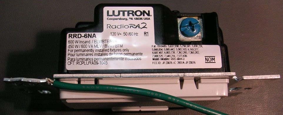
Click to zoom
Application Details
- Equipment Class
- DXT - Part 15 Low Power Transceiver, Rx Verified
- Date of Grant
- Feb 09, 2011
- Application Purpose
- Original Equipment
- Date of Application
- Feb 09, 2011
- Equipment Note
- Electronic Dimmer/Switch with RF Communication
- Frequency Range
- 431.00000000 - 437.00000000
- Country
- United States
Documents & Files
Document Text
Text extracted from the exhibit documents filed with the FCC. Open a document above to read the original.
Users Manual
1 When using controls in single location installations, tighten the blue terminal without any wires attached. Do not connect the blue terminal to any other wiring or to ground. 2 Up to 9 Remote Dimmers / Switches may be connected to a Dimmer / Switch. total blue terminal wire length may be up to 250 ft (76 m). 3 neutral wire Dimmers / Switches must be connected on the Load side of a multi- location installation. Designer-Style RF Maestro® Dimmers: RRD-6D, -6NA, -10D, -10ND Switch: RRD-8ANS Typical Power Consumption*: 0.2 W Remote Dimmer: RD-RD Remote Switch: RD-RS Typical Power Consumption*: 0 W 120 V 50 / 60 Hz Installation Instructions Please Read Before Installing Multigang Installations In multigang installations, several controls are grouped horizontally in one multigang wallbox. When combining controls in a wallbox, derating is required; however, no derating is required for Remote Dimmers / Switches. Derating Chart ControlLoad Type End of Gang Middle of Gang -6D Incand.500 W400 W MLV 400 W / 500 VA 300 W / 400 VA -6nA Incand./ E LV 500 W400 W MLV 400 W / 500 VA 300 W / 400 VA -10D, -10nD Incand.800 W650 W MLV 600 W / 800 VA 500 W / 650 VA -8AnS Lighting6.5 A5 A Motor 1/4 HP 5.8 A 1/6 HP 4.4 A Note: -8AnS controls have fins that need to be removed for multigang installations. -6D, -6nA, -10D, -10nD, -RD and -RS controls do not have fins that need to be removed for multigang installations. Multi-Location Installation without neutral 2 -6D and -10D with RD-RD Wiring Diagram 1b Single Location Installation with neutral 1 -6nA, -10nD, and -8AnS 120 V 50 / 60 Hz Brass Silver Black Blue tighten 1 Green Ground Hot/Live neutral Load Wiring Diagram 2a Single Location Installation without neutral 1 -6D and -10D Wiring Diagram 1a Multi-Location Installation with neutral 2, 3 -6nA and -10nD with RD-RD, and -8AnS with RD-RS Dimmer / Switch Status LEDs (Dimmer Only) Indicate light level; glows softly as night light when load is off Tapswitch tap on/off Dimming Rocker Press to Brighten Press to Dim FASS TM Front Accessible Service Switch Dimmer Operation Switch Operation Lamp Replacement WARNING - Shock Hazard - For any procedure other than routine lamp replacement, power must be disconnected at the main electrical panel. Working with power on could result in serious injury or even death. For your safety during routine lamp replacement, remove power from the fixture(s) by pulling the FASS switch out on both the Dimmer / Switch and all Remote Dimmers / Switches. Troubleshooting Guide Lutron Elec tron ics Co., Inc. 7200 Suter Road Coopersburg, PA 18036-1299 Print ed in the U.S.A. 01 / 11 P/n 044-264 Rev. A Dimmer Status LED (Switch Only) Indicates light status; glows softly as night light when load is off Tapswitch tap on/off FASS Front Accessible Service Switch Brass Black Blue tighten 1 Green Ground Hot/Live neutral Lighting Load Dimmer Brass Black Blue Green Ground Lighting Load Dimmer or Remote Dimmer Brass Black Blue Green Ground Remote Dimmer or Dimmer 120 V 50 / 60 Hz Brass Black Blue Green Ground Hot/Live neutral Remote Dimmer or Dimmer Brass Silver Black Blue Green Ground Load Brass Black Blue Green Ground Remote Dimmer/Switch 120 V 50 / 60 Hz Brass Black Blue Green Ground Hot/Live neutral Remote Dimmer/Switch Dimmer / Switch Wiring Diagram 2b Switch 120 V 50 / 60 Hz • Screw terminals: use with 12 AWG (2.5 mm 2 ) or 14 AWG (1.5 mm 2 ) solid copper wire only. Do not use stranded or twisted wire. Wrap wire around screw terminal. tighten securely to 5 in-lbs (0.55 N•m). b. Wire Connectors: Prepare wires. When making wire connections, follow the recommended strip lengths and combinations for the supplied wire connector. Note: Wire connector provided is suitable for copper wire only. Wire Connector: • Strip insulation 3/8 in (10 mm) for 14 AWG (1.5 mm 2 ) or 12 AWG (2.5 mm 2 ) wire • Strip insulation 7/16 in (11 mm) for 18 AWG (0.75 mm 2 ) wire • Use to join one or two 14 AWG (1.5 mm 2 ) or 12 AWG (2.5 mm 2 ) wires with one 18 AWG (0.75 mm 2 ) ground wire. For installations WItHoUt a neutral wire: See Wiring Diagram 1a or 1b. For installations WItH a neutral wire: See Wiring Diagrams 2a or 2b. Note: If a neutral wire connection is available, connect it to the silver terminal. 4. Push all wires back into the wallbox and loosely fasten the control to the wallbox using the control mounting screws provided. Do not pinch the wires. 5. Attach the Lutron Claro or Satin Colors wallplate adapter and wallplate. a. Install wallplate adapter onto front of control(s). b. tighten control mounting screws until wallplate adapter is flush to wall (do not over-tighten). c. Snap wallplate onto wallplate adapter, and verify that control is aligned properly. d. If controls are misaligned, loosen mounting screws appropriately. 6. Restore power. Verify correct local operation (see Dimmer Operation and Switch Operation). SymptomProbable Cause and Action Lights don’t switch on / oFF when tapswitch on Dimmer / Switch/ Remote is pressed Power not present • Circuit breaker OFF or tripped. Perform Short Circuit Check. • FASS is in the oFF position. Move FASS to the on position by fully pushing it in. Check both the Dimmer / Switch and all of the Remote Dimmers / Switches. Wiring • Wires shorted. Make sure the blue terminal is not grounded or shorted to any other wires. • Wiring error. Check wiring to be sure it agrees with installation instructions and wiring diagrams. • Increase load to meet the appropriate minimum load requirement. See Load Specifications. Lamps burned out or not installed • Replace or install lamps. Dioded lamps • If dioded lamps are being used, replace with non-dioded lamps. Light turns on and oFF continuously or lights turn on when tapswitch is pressed, then turn oFF Load is less than minimum load requirement • Make sure the connected load meets the appropriate minimum load requirement for that control. See Load Specifications. Lights don’t switch on/oFF from a Keypad Improper programming • Program acc…
Text truncated - open the document above for the full version.
Users Manual
© 2009 Lutron Electronics Co., Inc. Lutron Electronics Co., Inc. 7200 Suter Road Coopersburg, PA 18036 Made and printed in the U.S.A. Hecho e impreso en los E.U.A. Réalisé et imprimé aux Etats-Unis Editado e impresso nos E.U.A. 9 / 09 P/N 043-276 Rev. A English For installation instructions and warranties in different lan- guages, please go to the link below: Español Si desea instrucciones y garantías de instalación en otros idiomas, visite el siguiente enlace: Français Pour obtenir des instructions d’installation et garanties dans d’autres langues, veuillez utiliser le lien suivant : Português Para obter instruções de instalação e garantias noutros idiomas, visite: Deutsch Installationsanweisungen und Garantien in verschiedenen Sprachen finden Sie unter: Nederlands Ga voor installatie-instructies en garanties in andere talen naar de koppeling hier onder: Italiano Per le istruzioni d’installazione e le garanzie in una lingua diversa, selezionare il link sottostante: www.lutron.com/resiinfo Limited Warranty Garantie Limitée GarantÍa Limitada Garantia Limitada GarantÍa Limitada Exclusivamente en el caso de México ESPAÑOL PÓLiZa de GarantÍa LUTRON CN, S. de R.L. de C.V., RFC: LCN020626TD1, GABRIEL MANCERA 1041, COL. DEL VALLE 03100, MÉXICO D.F., MÉXICO, Tel. +1.888.235.2910 o +1.610.282.6701, garantiza todas las piezas y servicio de este producto por cualquier defecto de fabricación que exista y la eficiencia del mismo durante un (1) año, considerado a partir de la fecha de entrega o de instalación del producto, bajo las siguientes: CondiCiones: 1. Para hacer efectiva esta garantía, las reclamaciones no se podrán hacer si no es presentando esta póliza y el producto defectuoso en el lugar donde se compró el producto, en cualquira de los centros de servicio que se indican más adelante. El consumidor tambien podra comprar partes, componentes, consumibles y accesorios en dicho lugar. 2. LUTRON reemplazará o intercambiará el producto defectuoso sin hacer más cargos al cliente. Los gastos de transporte (si los hubiera) los cubrirá LUTRON CN, S. de R.L. de C.V. 3. El tiempo para reemplazar el producto no excederá de treinta (30) días, contados a partir del momento en que se reciba el producto en cualquiera de los lugares en donde esta garantía se pueda hacer efectiva. 4. Cuando se necesite hacer efectiva esta garantía reemplazando el producto, el trámite se hará en LUTRON CN, S. de R.L. de C.V. 5. Esta garantía perderá su validez en los casos siguientes: (A) Cuando el producto se haya usado en condiciones que no sean las normales. (B) Cuando el producto se haya hecho funcionar sin seguir las instrucciones del producto que vienen en español. (C) Cuando alguna(s) persona(s), no autorizada(s) por LUTRON CN, S. de R.L. de C.V., haya(n) alterado o reparado el producto. 6. El cliente podrá solicitar que esta póliza se haga efectiva en el establecimiento comercial donde se compró el producto. 7. En caso de que esta garantía se extravíe, el cliente podrá solicitar otra póliza de garantía al proveedor una vez que presente el recibo o factura de compra. NOMBRE: COL.: CIUDAD: ESTADO: TELÉFONO: DIRECCIÓN: C.P.: NOMBRE COMERCIAL: MARCA: NO. DE SERIE: NO. DE DISTRIBUIDOR: DIRECCIÓN: COL.: CIUDAD: ESTADO: TELÉFONO: FECHA DE VENTA: FECHA DE ENTREGA O DE INSTALACIÓN: PRODUCTO: MODELO: C.P.: inFormaCiÓn deL ConsUmidor inFormaCiÓn deL estaBLeCimiento o Vendedor PORTUGUÊS Sujeita às exclusões descritas abaixo, durante um período (definido abaixo) após a data de remessa por parte da Lutron, a Lutron garante que cada novo produto (“Produto”) estará isento de defeitos de fabricação. A Lutron, a seu critério, reparará a peça defeituosa ou fornecerá as peças de substituição comparáveis, desde que a Lutron seja prontamente notificada do defeito dentro do período de garantia (definido abaixo). As peças de substituição fornecidas pela Lutron podem ser novas, usadas, reparadas, recondicionadas e/ou feitas por um fabricante diferente. eXCLUsÕes da Garantia Limitada Esta Garantia não cobre e nem a Lutron e seus fornecedores serão responsáveis por: 1. Dano, mau funcionamento ou inoperabilidade diagnosticados pela Lutron ou terceiros aprovados pela Lutron causados pelo desgaste normal, mau uso, uso exces- sivo, instalação correta, negligência, acidente ou interferência das fontes de infravermelho ou freqüência de rádio ou obstáculos, tais como, entre outros, (a) uso de voltagens de linha, fusíveis e disjuntores incorretos; (b) falha na instalação, manutenção e operação do Produto em conformidade com as instruções operacionais fornecidas pela Lutron e as disposições aplicáveis do Código Elétrico Nacional dos EUA e das Normas de Segurança dos Underwriter’s Laboratories; (c) uso de aparelhos ou acessórios incompatíveis; (d) falha na manutenção do equipamento sob a temperatura ambiente especificada; (e) reparos ou ajustes não autoriza- dos; (f) vandalismo; e (g) um caso fortuito, como incêndio, relâmpago, inundação, tornado, terremoto, furacão ou outros problemas fora do controle da Lutron. 2. Custo de mão-de-obra no local para diagnosticar questões e remover, reparar, substituir, ajustar, reinstalar e/ou reprogramar o Produto, a critério da Lutron, sendo todos os custos pagos pelo Cliente ao preço atual do serviço. 3. Quando aplicável, os componentes e os equipamentos externos do Produto, como, lâmpadas, lastros que não sejam da Lutron, soquetes e acessórios; cabeamento do acessório entre os lastros e as lâmpadas; cabeamento das instalações entre os redutores de luz ou painéis do redutor de luz e lâmpadas e entre os controles, redutores de luz ou painéis do redutor de luz; e outros equipamentos dos fabricantes não fornecidos pela Lutron, como relógios, equipamentos audiovisuais, detectores de movimento, fotossensores, sensores de entrada para carros, almofadas de pressão, persianas e banheiras. 4. O custo de reparar ou substituir outras propriedades que tenham sido danificadas quando o produto não funciona corretamente, mesmo que o …
Text truncated - open the document above for the full version.
Block Diagram
Micro-controller (26MHz Clock, 13MHz Bus) CC1101 RF Transceiver (26MHz Clock, 203KHz IF, fc-IF L0) 3MHz SPI 62.5KHz Data FETs (Load Control) 26MHz Crystal Buttons LED's (PWM at 1.11 kHz) Power Supply (132KHz Switching Supply) Resonant Loop Antenna 431-437 MHz fc Frequency Table RF Section -Carrier Frequency (fc) between 431 and 437 MHz (Transmit) -Intermediate Frequency (IF) of 203KHz -LO Frequency equal to fc-IF(Receive) -3MHz SPI interface (Configuration control from micro controller) -62.5KHz bi-directional data Micro-Controller -26MHz Clock -13MHz Bus -3MHz SPI interface (CC1101) -1 MHz SPI Interface (EEPROM) -62.5KHz bi-directional data -1.11 Khz PWM Signal for LED Brightness Control -120Hz Control Signal for Triac (Dimming) Control Power Supply -132 Khz switching signal EEPROM 1 MHz SPI
Cover Letter(s)
Underwriters Laboratories, Inc. 333 Pfingsten Road Northbrook, IL 60062 17 January 2011 Subject: Authorization to act as Agent Dear Sir or Madam: This letter is to formally give Underwriters Laboratories the authorization to act as agent for the purpose of FCC and IC submission and answering of technical questions to UL CCS. Sincerely, Steve O’Donnell
Cover Letter(s)
Lutron® | 1www.lutron.com/radiora2 product specifications 11.18.10 369-225e RadioRA 2 Maestro local controls function much like standard dimmers and switches, but can be controlled as part of a lighting control system. Local lighting controls are useful in locations where single circuits of lighting need to be dimmed or switched. RadioRA 2 Maestro dimmers incorporate advanced features such as fade on / fade off, delayed long fade to off, and rapid full on. RadioRA 2 Maestro local controls include a Front Accessible Service Switch (FASS TM) for safe lamp replacement. RadioRA 2 Maestro local controls install in single-pole or multi-location applications. Remote dimmers / switches are available for multi-location control. Use Lutron ® Designer (Claro® or Satin Colors®) wallplates or designer-style wallplates from other manufacturers. Wallplates are sold separately. Lutron Claro and Satin Colors wallplates snap on with no visible means of attachment. RadioRA 2 Maestro local controls support color change kits. Model Numbers Dimmers Incandescent / Halogen / MLV (120 V ) RRD-6D-XX* 600 W / 600 VA Dimmer RRD-10D-XX* 1000 W / 1000 VA Dimmer RRD-10ND-XX* 1000 W / 1000 VA Neutral Wire Dimmer Incandescent / Halogen / MLV / ELV (120 V ) RRD-6NA-XX* 600 W / 600 VA Neutral Wire Adaptive Dimmer 3-Wire Fluorescent/LED (120-277 V ) RRD-F6AN-DV-XX* 6 A Neutral Wire Dimmer Switches Lighting and Motor Loads (120 V ) RRD-8ANS-XX* 8 A Light, 1/4 HP 5.8 A Motor Neutral Wire Electronic Switch Lighting and Motor Loads (120-277 V ) RRD-8S-DV-XX* 8 A Light, 1/10 HP 3 A Motor Two-Wire Electronic Switch RadioRA 2 Maestro® Local Controls Switch DimmerRemote Dimmer Remote Switch Remotes (for multi-location installations) RD-RD-XX* Remote Dimmer (120 V ) RD-RS-XX* Remote Switch (120 V ) RD-RD-277-XX* Remote Dimmer (277 V ) Use only with -F6AN-DV RD-RS-277-XX* Remote Switch (277 V ) Use only with -8S-DV Color Change Kits RK-D-XX* Dimmers (-6D, -10D, -10ND, -6NA, and -F6AN-DV) RK-S-XX* Switches (-8ANS and -8S-DV) RK-AD-XX* Remote Dimmers (-RD) RK-AS-XX* Remote Switches (-RS) * RadioRA 2 Maestro local controls are available in 27 colors. Please see page 10 for color selections. 2 | Lutron®24/7 Technical Support—800.523.9466 product specifications 11.18.10 369-225e RadioRA 2 Maestro® Local Controls Specifications Model NumbersDimmer: RRD-6D-XX, RRD-10D-XX, RRD-10ND-XX, RRD-6NA-XX, RRD-F6AN-DV-XX Switch: RRD-8ANS-XX, RRD-8S-DV-XX Remote: RD-RD-XX, RD-RS-XX, RD-RD-277-XX, RD-RS-277-XX Power120 V 50 / 60 Hz (-6D, -10D, -10ND, -6NA, -8ANS, -RD, -RS) 120 – 277 V 50 / 60 Hz (-F6AN-DV, -8S-DV) 277 V 50 / 60 Hz (-RD-277, -RS-277) Typical Power Consumption Dimmer / Switch: 0.2 W Test conditions: load is off and nightlight mode is enabled. Remote Dimmer / Switch: 0 W Test conditions: load is off. Regulatory ApprovalsUL, CSA (all except -6NA), cUL (-6NA only), NOM, FCC, IC, COFETEL EnvironmentAmbient operating temperature: 32 °F to 104 °F (0 °C to 40 °C), 0% to 90% humidity, non-condensing. Indoor use only. CommunicationsDimmers and switches communicate with the system through Radio Frequency (RF) and must be located within 30 ft (9 m) of a repeater. Remote dimmers / switches are not required to be within a specific range of a repeater. System devices operate on frequencies between 431.0 MHz and 437.0 MHz. ESD ProtectionTested to withstand electrostatic discharge without damage or memory loss, in accordance with IEC 61000-4-2. Surge ProtectionTested to withstand surge voltages without damage or loss of operation, in accordance with IEEE C62.41-1991 Recommended Practice on Surge Voltages in Low-Voltage AC Power Circuits. Power FailurePower failure memory: should power be interrupted, the control will return to its previous state when power is restored. MountingRequires a U.S. wallbox. 3 ½ in (89 mm) deep recommended, 2 ¼ in (57 mm) deep minimum. WiringUses conventional 3-way and 4-way wiring. Warranty1 Year Limited Warranty. http://www.lutron.com/resiinfo Dimmer • On a single-tap, lights fade ON or OFF. • On a double-tap, lights go to full ON. • When ON, press and hold the tapswitch to engage the delayed long fade to OFF. • Light levels can be fine-tuned by pressing and holding the dimming rocker until the desired light level is reached. • Neutral and two-wire dimmers available. Design Features Switch • On a single-tap, lights or motors turn ON or OFF. • Neutral and two-wire switches available. Lutron® | 3www.lutron.com/radiora2 product specifications 11.18.10 369-225e Dimensions All dimensions are shown as in (mm) Mounting and Parts Identification Front View Side View 5/16 (8) 1 1 ⁄8 (30) 4 11 ⁄16 (119) 2 15 ⁄16 (75) RadioRA 2 Maestro® Local Controls Wallbox Control Adapter Mounting Screws Control Mounting Screws Wallplate Adapter / Wallplate purchased separately. Wallplate Wallplate Adapter 5/16 (8) 1 3 ⁄8 (35) -RD-277 and -RS-277 only Side View 4 | Lutron®24/7 Technical Support—800.523.9466 product specifications 11.18.10 369-225e Ganging and Derating Load Type and Capacity When combining controls in the same wallbox, derating is required. See Load Type and Capacity. No derating is required for remote dimmers / switches. -8ANS, -RD-277, and -RS-277 have fins that need to be removed for multigang installations. Do Not remove outside fins on end of gang controls -8ANS, -RD-277, and -RS-277 only: Middle of gang control has all fins removed Each control has inside fins removed RadioRA 2 Maestro® Local Controls ControlLoad TypeMinimum Load Not Ganged End of Gang Middle of Gang Neutral Connection RRD-6D 1 Incand.50 W600 W500 W400 W NO M LV 2 50 W / VA 450 W / 600 VA 400 W / 500 VA 300 W / 400 VA RRD-10D 1 Incand.50 W1000 W800 W650 W NO M LV 2 50 W / VA 800 W / 1000 VA 600 W / 800 VA 500 W / 650 VA RRD-10ND 1, 4 Incand.10 W1000 W800 W650 W YES M LV 2 10 W / VA 800 W / 1000 VA 600 W / 800 VA 500 W / 650 VA RRD-6NA 1, 4 Incand. / E LV 5 W600 W500 W400 W YES M LV 2 5 W / VA 450 W / 600 VA 400 W / 500 VA 300 W / 400 VA RRD-F6AN-DV 3, 4, 5 Fluo…
Text truncated - open the document above for the full version.
External Photos
RRD-6NA Construction Photographs RRD-6NA (Front) RRD-6NA (Back) RRD-6NA (Side 1) RRD-6NA is the base unit, used for commercial purposes. RRD-RNA-U is the Model number, of the base unit’s construction, for certification with Industry Canada. RRD-6NA (Side 2)
Internal Photos
RRD-6NA Construction Photographs RRD-6NA is the base unit, used for commercial purposes. RRD-RNA-U is the Model number, of the base unit’s construction, certified with Industry Canada. RRD-6NA (Front) RRD-6NA (PCB Front 1) RRD-6NA (PCB Front 2) RRD-6NA (Antenna) RRD-6NA (PCB Back 1) RRD-6NA (PCB Back 2)
Test Report
Underwriters Laboratories Inc. A not-for-profit organization dedicated 1285 Walt Whitman Rd. to public safety and committed to Melville, NY 11747 quality service for over 100 years Tel: (631) 271-6200 Fax: (631)439-6095 Underwriters Laboratories Inc. 1285 Walt Whitman Rd. Melville, NY 11747 www.ul.com/emc (631) 271-6200 Job Number: 1001313517 Project Number: 10CA58780 File Number: MC15896 Date: 2011-01-07 Model: RRD-6NA FCC ID: JPZ0076 IC ID: 2851A-JPZ0076 Electromagnetic Compatibility Test Report For LUTRON ELECTRONICS INC Copyright 2010 Underwriters Laboratories Inc. Underwriters Laboratories Inc. authorizes the above-named company to reproduce this Report provided it is reproduced in its entirety. Job Number: 1001313517 File Number: MC15896 Page 2 of 89 Model Number: RRD-6NA Client Name: LUTRON ELECTRONICS INC FCC ID: JPZ0076 IC ID: 2851A-JPZ0076 Underwriters Laboratories Inc. 1285 Walt Whitman Rd. Melville, New York 11747 USA Tel.: 631 271-6200 Fax: 631 439-6095 Rev. No 1.0 EMC Report 2010-87-EM-F0042 Test Report Details Tests Performed By: Underwriters Laboratories Inc. 1285 Walt Whitman Rd. Melville, NY 11747 Tests Performed For: LUTRON ELECTRONICS INC 7200 SUTTER ROAD COOPERBURG, PA 18036 Applicant Contact: BOB SPEHALSKI Phone: (610) 282-7424 E-mail: [email protected] Test Report Date: 2011-01-07 Product Type: Wall Mounted Dimmer/Switch Product standards FCC Part 15, Subpart C, 15.231, RSS-GEN, RSS-210 Model Number: RRD-6NA Sample Serial Number: Not Available EUT Category: Periodic Low Power Transmitter Testing Start Date: 14 Dec 2010 Date Testing Complete: 22 Dec 2010 Overall Results: Compliant Underwriters Laboratories Inc. reports apply only to the specific samples tested under stated test conditions. All samples tested were in good operating condition throughout the entire test program. It is the manufacturer's responsibility to assure that additional production units of this model are manufactured with identical electrical and mechanical components. Underwriters Laboratories Inc. shall have no liability for any deductions, inferences or generalizations drawn by the client or others from Underwriters Laboratories Inc. issued reports. This report shall not be used to claim, constitute or imply product certification, approval, or endorsement by NVLAP, NIST, A2LA, or any agency of the US government. This report may contain test results that are not covered by the NVLAP or A2LA accreditation. The scope of accreditation is limited to the specific tests that are listed on the NVLAP and/or A2LA websites referenced at the end of this report. Job Number: 1001313517 File Number: MC15896 Page 3 of 89 Model Number: RRD-6NA Client Name: LUTRON ELECTRONICS INC FCC ID: JPZ0076 IC ID: 2851A-JPZ0076 Underwriters Laboratories Inc. 1285 Walt Whitman Rd. Melville, New York 11747 USA Tel.: 631 271-6200 Fax: 631 439-6095 Rev. No 1.0 EMC Report 2010-87-EM-F0042 Report Directory 1.0 G E N E R A L - Product Description ..................................................................................................................4 1.1 Equipment Description ...................................................................................................................................4 1.2 Equipment Marking Plate ...............................................................................................................................4 1.3 Device Configuration During Test ..................................................................................................................5 1.3.1 Equipment Used During Test: ....................................................................................................................5 1.3.2 Input/Output Ports: .....................................................................................................................................5 1.3.3 EUT Internal Operating Frequencies: ........................................................................................................6 1.3.4 Power Interface: .........................................................................................................................................6 1.4 Block Diagram: ...............................................................................................................................................7 1.5 EUT Configurations ........................................................................................................................................8 1.6 EUT Operation Modes ....................................................................................................................................8 2.0 Summary ............................................................................................................................................................9 2.1 Deviations from standard test methods ..........................................................................................................9 2.2 Device Modifications Necessary for Compliance ...........................................................................................9 2.3 Reference Standards ...................................................................................................................................10 2.4 Results Summary .........................................................................................................................................10 3.0 Calibration of Equipment Used for Measurement ............................................................................................11 4.0 Emissions Test Results ....................................................................................................................................11 4.1 Test Conditions and Results – MAINS TERMINAL – CONDUCTED EMISSIONS .....................................12 4.2 Test Conditions and Results – Occupied Bandwidth ...................................................................................40 4.3 Te…
Text truncated - open the document above for the full version.
Test Setup Photos
Job Number: 1001313517 File Number: MC15896 Page 14 of 89 Model Number: RRD-6NA Client Name: LUTRON ELECTRONICS INC FCC ID: JPZ0076 IC ID: 2851A-JPZ0076 Underwriters Laboratories Inc. 1285 Walt Whitman Rd. Melville, New York 11747 USA Tel.: 631 271-6200 Fax: 631 439-6095 Rev. No 1.0 EMC Report 2010-87-EM-F0042 Figure 1 Test Setup for Conducted Emissions Job Number: 1001313517 File Number: MC15896 Page 47 of 89 Model Number: RRD-6NA Client Name: LUTRON ELECTRONICS INC FCC ID: JPZ0076 IC ID: 2851A-JPZ0076 Underwriters Laboratories Inc. 1285 Walt Whitman Rd. Melville, New York 11747 USA Tel.: 631 271-6200 Fax: 631 439-6095 Rev. No 1.0 EMC Report 2010-87-EM-F0042 Figure 11 Test Setup for Cease Operation Job Number: 1001313517 File Number: MC15896 Page 56 of 89 Model Number: RRD-6NA Client Name: LUTRON ELECTRONICS INC FCC ID: JPZ0076 IC ID: 2851A-JPZ0076 Underwriters Laboratories Inc. 1285 Walt Whitman Rd. Melville, New York 11747 USA Tel.: 631 271-6200 Fax: 631 439-6095 Rev. No 1.0 EMC Report 2010-87-EM-F0042 Figure 15 Test setup for Radiated Emissions – XMT Mode Front View Rear View Job Number: 1001313517 File Number: MC15896 Page 57 of 89 Model Number: RRD-6NA Client Name: LUTRON ELECTRONICS INC FCC ID: JPZ0076 IC ID: 2851A-JPZ0076 Underwriters Laboratories Inc. 1285 Walt Whitman Rd. Melville, New York 11747 USA Tel.: 631 271-6200 Fax: 631 439-6095 Rev. No 1.0 EMC Report 2010-87-EM-F0042 Front View Rear View
Contact Information
Applicant
Daniel Schlegel(Standards Compliance Supervisor)
Technical Contact
Underwriters Laboratories IncRobert DeLisi
[email protected]631-546-2452
1285 Walt Whitman Rd. · Melville, New York · United States
Non-Technical Contact
Lutron Electronics Co IncRobert Spehalski
[email protected]610-282-7424
Test Firm
UL LLCRick Titus
Technical Specifications
| # | Rule Parts | Frequency Range | Power Output |
|---|---|---|---|
| 1 | 15C | 431 MHz - 437 MHz | - |
Other Applications from Lutron Electronics Company Inc
JPZ0161
Sep 03, 2026Wireless Interface
Equipment Class
DTS - Digital Transmission SystemJPZ0159
Aug 12, 2026Wireless Processor
Equipment Class
DTS - Digital Transmission SystemJPZ0158
Jul 27, 2026Copy of Wireless Processor
Equipment Class
DTS - Digital Transmission SystemJPZ0157
Mar 26, 2026LED Downlight
Equipment Class
DTS - Digital Transmission SystemJPZ0155
Sep 30, 2024LED Lighting Controller
Equipment Class
DTS - Digital Transmission System