JPZ0077Low Power Communication Device Transmitter
Lutron Electronics Company Inc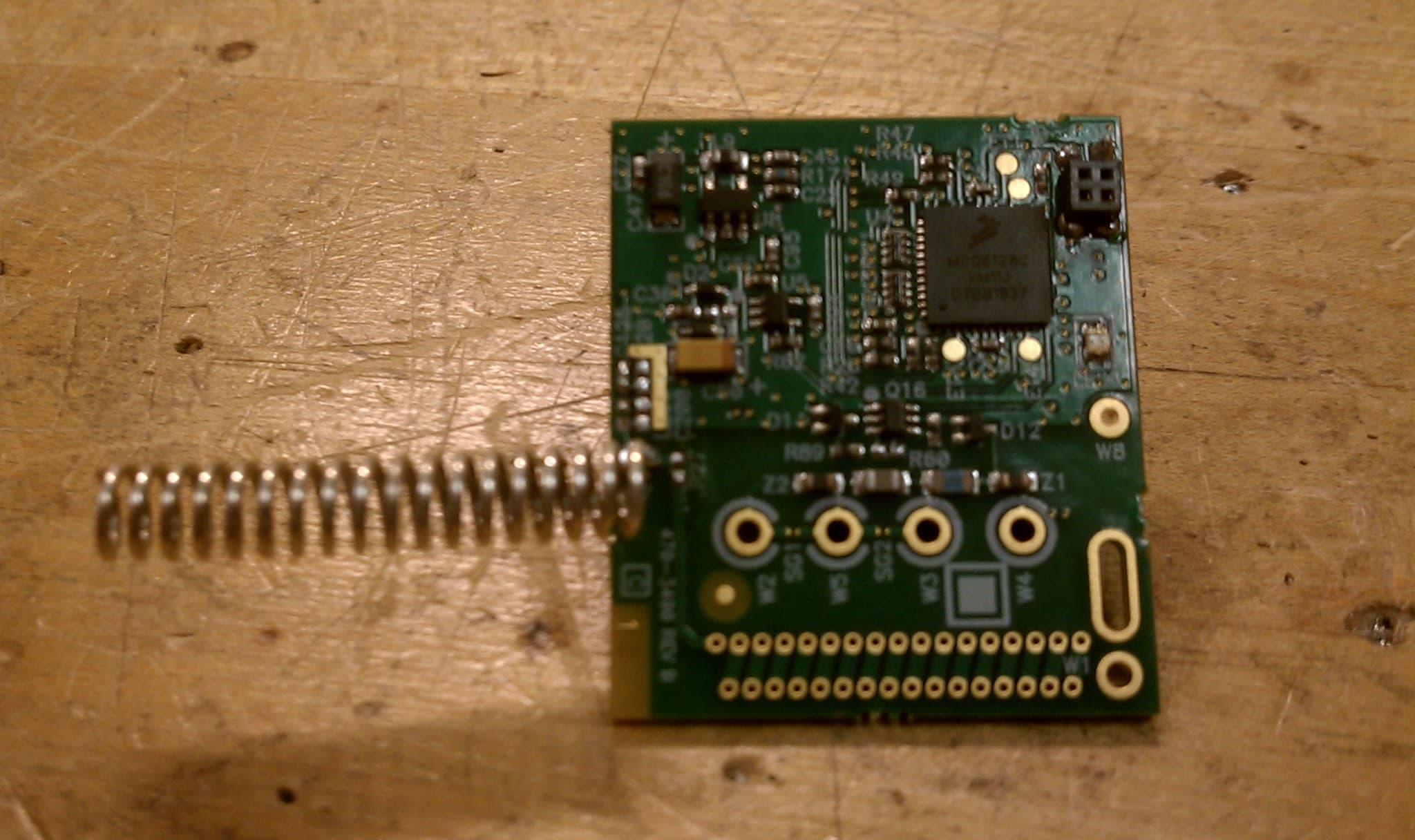
Click to zoom
Application Details
- Equipment Class
- DXX - Part 15 Low Power Communication Device Transmitter
- Date of Grant
- Aug 17, 2011
- Application Purpose
- Original Equipment
- Date of Application
- Aug 17, 2011
- Equipment Note
- Low Power Communication Device Transmitter
- Frequency Range
- 431.00000000 - 437.00000000
- Country
- United States
Documents & Files
Document Text
Text extracted from the exhibit documents filed with the FCC. Open a document above to read the original.
Users Manual
Specifications: Temperature Monitor Range: 32.2°F to 99.9°F (0.0°C to 37.7°C) Setpoint Range: 60.0°F to 85.0°F (15.5°C to 29.5°C) *Setpoint: 72°F (22°C) *Comfort Limits: 65.0°F (18.5°C) cooling 85.0°F (29.5°C) heating Display Format: Liquid Crystal Display (LCD) Backlight: EL blue green Sampling Rate: Every 15 seconds Accuracy: ± 1°F (0.5°C) Power Source: 24VAC/DC (20 minimum to 32 maximum) Load Rating: 1.5 amps per load circuit *Fan Control: Selectable: Auto cycle, Low, Medium, High Heat/Cool Control: 1 heat and 1 cool circuit (see system function) *Economy Limits: Maintains room temperature between 60.0°F and 85.0°F (15.5°C and 29.5°C) when thermostat is in economy (ECON) mode *Fan Purge Timer: 30 seconds Anti-short Cycle: 3 minute hold in no call state at all times *Cycle Rate: 8 cycles per hour * Differential: 0.4°F * Display Mode: Setpoint temperature * System Function: Heat and Cool *See Field Programming Instructions Application: This thermostat is a 24 volt heating and cooling digital temperature control designed to operate 2 or 4-pipe fan coil systems. Switching of load circuits is through relay contacts. Fan outputs can be configured to operate 3, 2 or single speed fan motors. The fan control also has configurations for user select fan speed with economy function, continuous fan or auto cycle fan. This thermostat operates on a single setpoint with automatic changeover from heating to cooling. Installation Notice: This high performance digital thermostat is designed to provide many years of superior comfort control when properly installed and maintained. To achieve maximum performance, this device is designed to draw room air into itself continuously. Reasonable care must therefore be taken with regard to air quality at the time of installation as well as during periods of normal use, see operating conditions below. Operating Conditions: The electronic mechanisms incorporated within this unit REQUIRE operating conditions similar to other electronic devices intended for INDOOR USE ONLY, such as would be acceptable for TV and similar household appliances. Relative humidity must be less than 95% and the atmosphere must be non-condensing. For operation in bathrooms, shower or pool areas, outdoor entry ways, greenhouses and similar applications, order the “-k” option. This product includes protection for coastal/tropical application, therefore it is suitable for use in high humidity environments. Air quality must be maintained FREE of heavy dust or debris which may infiltrate the interior of this device. Installation in any space which is unfinished or undergoing repainting or general rehabilitation is also considered product abuse. This device should be removed from service during any local construction activity. Cleaning: This device incorporates a high impact polycarbonate enclosure which is easily cleaned with a dry cloth or vacuum brush. Occasional soiling may be cleaned with a soft cloth lightly dampened with water and/or mild cleaning solution. IN NO CASE should this device be directly sprayed with or exposed to free flowing liquids, including water, which could penetrate its interior. FAILURE TO OBSERVE ANY OF THE ABOVE CONDITIONS OF USE WILL COMPLETELY VOID THE SUPPLIER WARRANTY. CAUTION MAKE SURE UNIT IS PROPERLY CONNECTED. DAMAGE TO THE DIGITAL CONTROL CAN BE CAUSED BY MISWIRING, WHICH WILL VOID THE WARRANTY. FOR SAFETY REASONS ALWAYS USE WIRE NUTS ON ALL WIRE CONNECTIONS!!! ◦ +3V SB1 SB2 COM SEN3 SEN2 REF +3V SB1 SB2 COM +3V SB1 SB2 COM ◦ ◦ Installation and Operating Instructions Premier Series 24 Volt PFC-M24 PFC-M24-RS SETPOINT AUTO ◦ ◦ System Mode Switch H E A T / A U T O / C O O L ° F /° C PFC-A24 PFC-A24-RS SETPOINT AUTO ◦ ◦ Decrease temperature Switches between °F and °C Selects fan function Increase temperature ° F / ° C 4-PIPE FAN COIL, 2-PIPE ELECTRIC HEAT OR ELECTRONIC AQUASTAT INSTALLATION: This device should be installed and serviced by a qualified technician. Junction box mounting is highly recommended. 1. Caution: Make sure that power has been disconnected. 2. All wiring must comply with applicable codes and ordinances. 3. A thorough check-out of the system should be made after installation is complete. 4. If fan motor is larger than 1/4 HP and/or electric heaters are used for heating, additional power relays will be required 5. If retrofitting old thermostat, remove old thermostat from the junction box, carefully noting the wire connections on the old unit. Record wire color and terminal legends in spaces provided. Disconnect old thermostat and remove any existing backplate or mounting plate. Old thermostat wire function Power Feed Common Heat Cool Low Fan Medium Fan High Fan Cable wire color User Note: The top of this unit will become warm to the touch. This is a normal operation. Internal heating is employed to continuously convect air upward through the thermostat, thereby improving room air temperature measurement. Direct conflict with a downward ceiling fan or system fan air flow may result in false temperature reading. Locate thermostat to avoid interference. Screw: 6/32 x 3/4" Mounting Bracket Standard Junction Box 6. Install the mounting bracket to the junction box with the two long mounting screws provided. See mounting detail to the right. Note: If application involves a double ganged junction box, a backplate will be required for a complete installation. Please consult your supplier. 1 ◦ SEN3 SEN2 REF +3V SB1 SB2 COM ◦ ◦ ◦ New Stat Wire Function Control Feed Load Feed Common Heat Cool Low Fan Medium Fan High Fan New Stat Wire Color Red Orange Black White Yellow Green Blue Violet Cable Wire Color 7. From the wire chart found in step 5, assign, according to function, the cable wire colors to the thermostat wire legend provided below. Note: The control feed and the load feed will be connected together for the 4-pipe installation. If this is a new installation, record the cable wire colors in the thermostat legend provided below. 8. Connect the therm…
Text truncated - open the document above for the full version.
Users Manual
LUTRON ELECTRONICS CO., INC. February, 2011 Page 1 of 1 Installation guide Applicable Model Numbers: X1019 Installation Instructions: The Clear Connect Module, model number X1019 with FCC ID JPZ0077, may only be installed into PSG thermostat, model number LUT-PFC-EO-2010-CPN5610. To install, place the Clear Connect Module on the 8 header pins on the backside of the PSG module with the antenna pointing to the top of the module. The entire enclosure must be mounted onto a metal back box to ensure FCC compliance. Please see Appendix A for the FCC statement for licensing information. Appendix A: FCC Information Note: This equipment has been tested and found to comply with the limits for a Class B digital device, pursuant to Part 15 of the FCC rules. These limits are designed to provide reasonable protection against harmful interference in a residential installation. This equipment generates, uses and can radiate radio frequency energy and, if not installed and used in accordance with the instructions, may cause harmful interference to radio or television reception. However, there is no guarantee that interference will not occur in a particular installation. If this equipment does cause harmful interference to radio or television reception, which can be determined by turning the equipment off and on, the user is encouraged to try to correct the interference by one or more of the following measures: • Reorient or relocate the receiving antenna. • Increase the seperation between the equipment and receiver. • Connect the equipment into an outlet on a circuit different from that to which the receiver is connected. • Consult the dealer or an experienced radio/TV technician for help. Caution: Changes or modifications not expressly approved by Lutron Electronics Co. could void the user’s authority to operate this equipment. Operation is subject to the following: (1) This device may not cause harmful interference, and (2) this device must accept any interference received, including interference that may cause undesired operation.
Block Diagram
Crystal 26 Mhz CC1101 RF Transceiver 26 MHz Clock, 203Khz IF Microcontroller 13Mhz EEPROM Helical-shaped Antenna Contact Closures 1 3 4 2 Frequency Table RF Section -Carrier Frequency between 431 and 437 MHz (transmit mode) (4) -Intermediate Frequency (IF) of 203kHz -LO Frequency equal to fc-IF (receive mode) -3.25MHz SPI interface (configuration control from micro controller) (2) -26MHz crystal oscillator (3) Micro-Controller-13MHz bus -3.25 MHz SPI interface (RF Transceiver) (2) -812.5kHz SPI interface (EEPROM) (1) -26MHz crystal oscillator (3) *Note: Numbers, e.g. (1), correspond to th e data and clock lines numbered on the block diagram.
Test Report
Underwriters Laboratories Inc. A not-for-profit organization dedicated 1285 Walt Whitman Rd. to public safety and committed to Melville, NY 11747 quality service for over 100 years Tel: (631) 271-6200 Fax: (631)439-6095 Underwriters Laboratories Inc. 1285 Walt Whitman Rd. Melville, NY 11747 www.ul.com/emc (631) 271-6200 Job Number: 1001345027 Project Number: 11CA09928 File Number: MC15896 Date: 2011-02-22 Model: X1019 FCC ID: JPZ0077 Electromagnetic Compatibility Test Report For LUTRON ELECTRONICS INC Copyright 2010 Underwriters Laboratories Inc. Underwriters Laboratories Inc. authorizes the above-named company to reproduce this Report provided it is reproduced in its entirety. Job Number: 1001345027 File Number: MC15896 Page 2 of 39 Model Number: X1019 Client Name: LUTRON ELECTRONICS INC FCC ID: JPZ0077 Underwriters Laboratories Inc. 1285 Walt Whitman Rd. Melville, New York 11747 USA Tel.: 631 271-6200 Fax: 631 439-6095 Rev. No 1.0 EMC Report 2010-87-EM-F0042 Test Report Details Tests Performed By: Underwriters Laboratories Inc. 1285 Walt Whitman Rd. Melville, NY 11747 Tests Performed For: LUTRON ELECTRONICS INC 7200 SUTTER ROAD COOPERBURG, PA 18036 Applicant Contact: Dan Mitchell Title: Senior Engineering Technician Phone: (610) 282-5370 E-mail: [email protected] Test Report Date: 2011-02-22 Product Type: Low Power Periodic Transmitter Product standards FCC Part 15, Subpart C, 15.231, RSS-GEN Issue 3, RSS-210 Issue 8 Model Number: X1019 Sample Serial Number: Non-serialized production unit EUT Category: Periodic Low Power Transmitter Testing Start Date: 2011-02-15 Date Testing Complete: 2011-02-21 Overall Results: Compliant Underwriters Laboratories Inc. reports apply only to the specific samples tested under stated test conditions. All samples tested were in good operating condition throughout the entire test program. It is the manufacturer's responsibility to assure that additional production units of this model are manufactured with identical electrical and mechanical components. Underwriters Laboratories Inc. shall have no liability for any deductions, inferences or generalizations drawn by the client or others from Underwriters Laboratories Inc. issued reports. This report shall not be used to claim, constitute or imply product certification, approval, or endorsement by NVLAP, NIST, A2LA, or any agency of the US government. This report may contain test results that are not covered by the NVLAP or A2LA accreditation. The scope of accreditation is limited to the specific tests that are listed on the NVLAP and/or A2LA websites referenced at the end of this report. Job Number: 1001345027 File Number: MC15896 Page 3 of 39 Model Number: X1019 Client Name: LUTRON ELECTRONICS INC FCC ID: JPZ0077 Underwriters Laboratories Inc. 1285 Walt Whitman Rd. Melville, New York 11747 USA Tel.: 631 271-6200 Fax: 631 439-6095 Rev. No 1.0 EMC Report 2010-87-EM-F0042 Report Directory 1.0 G E N E R A L - Product Description ..................................................................................................................4 1.1 Equipment Description ...................................................................................................................................4 1.2 Equipment Marking Plate ...............................................................................................................................4 1.3 Device Configuration During Test ..................................................................................................................5 1.3.1 Equipment Used During Test: ....................................................................................................................5 1.3.2 Input/Output Ports: .....................................................................................................................................5 1.3.3 EUT Internal Operating Frequencies: ........................................................................................................6 1.3.4 Power Interface: .........................................................................................................................................6 1.4 Block Diagram: ...............................................................................................................................................7 1.5 EUT Configurations ........................................................................................................................................8 1.6 EUT Operation Modes ....................................................................................................................................8 2.0 Summary ............................................................................................................................................................9 2.1 Deviations from standard test methods ..........................................................................................................9 2.2 Device Modifications Necessary for Compliance ...........................................................................................9 2.3 Reference Standards .................................................................................................................................. 10 2.4 Results Summary ........................................................................................................................................ 10 3.0 Calibration of Equipment Used for Measurement ........................................................................................... 11 4.0 EMISSIONS TEST RESULTS ......................................................................................................................... 11 4.1 Test Conditions and Results – MAINS TERMINAL – CONDUCTED EMISSIONS .................................... 12 4.2 Test Conditions and Results – Occupied Bandwidth .................................................................................. 19 4.3 Test Conditio…
Text truncated - open the document above for the full version.
Test Setup Photos
Job Number: 1001345027 File Number: MC15896 Page 14 of 39 Model Number: X1019 Client Name: LUTRON ELECTRONICS INC FCC ID: JPZ0077 Underwriters Laboratories Inc. 1285 Walt Whitman Rd. Melville, New York 11747 USA Tel.: 631 271-6200 Fax: 631 439-6095 Rev. No 1.0 EMC Report 2010-87-EM-F0042 Figure 1 Test Setup for Conducted Emissions Job Number: 1001345027 File Number: MC15896 Page 20 of 39 Model Number: X1019 Client Name: LUTRON ELECTRONICS INC FCC ID: JPZ0077 Underwriters Laboratories Inc. 1285 Walt Whitman Rd. Melville, New York 11747 USA Tel.: 631 271-6200 Fax: 631 439-6095 Rev. No 1.0 EMC Report 2010-87-EM-F0042 Figure 4 Test Setup for Occupied Bandwidth Job Number: 1001345027 File Number: MC15896 Page 31 of 39 Model Number: X1019 Client Name: LUTRON ELECTRONICS INC FCC ID: JPZ0077 Underwriters Laboratories Inc. 1285 Walt Whitman Rd. Melville, New York 11747 USA Tel.: 631 271-6200 Fax: 631 439-6095 Rev. No 1.0 EMC Report 2010-87-EM-F0042 Figure 10 Test setup for Radiated Emissions
Contact Information
Applicant
Daniel Schlegel(Standards Compliance Supervisor)
Technical Contact
Underwriters LaboratoriesBob Delisi
[email protected]631-546-2452
1285 Walt Whitman · Melville, New York · United States
Test Firm
UL LLCBob Delisi
Technical Specifications
| # | Rule Parts | Frequency Range | Power Output |
|---|---|---|---|
| 1 | 15C | 431 MHz - 437 MHz | - |
Other Applications from Lutron Electronics Company Inc
JPZ0161
Sep 03, 2026Wireless Interface
Equipment Class
DTS - Digital Transmission SystemJPZ0159
Aug 12, 2026Wireless Processor
Equipment Class
DTS - Digital Transmission SystemJPZ0158
Jul 27, 2026Copy of Wireless Processor
Equipment Class
DTS - Digital Transmission SystemJPZ0157
Mar 26, 2026LED Downlight
Equipment Class
DTS - Digital Transmission SystemJPZ0155
Sep 30, 2024LED Lighting Controller
Equipment Class
DTS - Digital Transmission System