JPZ0078Low Power Transceiver
Lutron Electronics Company Inc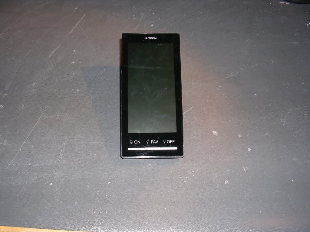
Click to zoom
Application Details
- Equipment Class
- DSR - Part 15 Remote Control/Security Device Transceiver
- Date of Grant
- Apr 05, 2011
- Application Purpose
- Original Equipment
- Date of Application
- Apr 05, 2011
- Equipment Note
- Low Power Transceiver
- Frequency Range
- 431.00000000 - 437.00000000
- Country
- United States
Documents & Files
Document Text
Text extracted from the exhibit documents filed with the FCC. Open a document above to read the original.
Users Manual
Troubleshooting Guide SymptomProbable Cause and Action Backlight does not turn on when screen is touched. Nothing is displayed on the screen. Power not present at keypad • Circuit breaker OFF. Turn ON breaker. Incorrect wiring. • Wire the keypad according to the Installation section. Blue Lutron® screen with “Maintenance” or “Startup failure” at the bottom. Startup failure. • Cycle power to the device. If symptom persists, contact Lutron Technical Support. The Dynamic Keypad does not control dimmers, shades or other system devices. All LEDs on the keypad flash when any button is pressed. • The device is in the Factory Default Settings mode and has not been activated into the system. Use the HomeWorks QS software to verify activation or re-active the device and transfer its database. Device is not communicating with the system. • Device is out of range of an RF signal repeater. Device is not properly programmed. • Program the device using the HomeWorks QS software All LEDs on the keypad flash when any button is pressed. The device is in the Factory Default mode and has not been activated into the system. • Use the HomeWorks QS software to verify activation or re-active the device and transfer its database. The Dynamic Keypad does not enter addressing mode. The Dynamic Keypad is not configured for RF communication. • Use the information screen on the Dynamic Keypad to verify that it is configured for RF communication. • Ensure MUX (pin 3) and MUX (pin 4) are not connected. The Dynamic Keypad does not snap onto the mounting frame as indicated in step 6c. The mounting frame screws may be too tight (Step 3B & 3D). • Remove the Dynamic Keypad, loosen the mounting frame screws and repeat step 6. Returning Dynamic Keypads to Factory Settings Returning Dynamic Keypads to Factory Settings will remove them from the system and erase all programming. Step 1: Triple tap any button, below the screen, on the Dynamic Keypad. DO NOT release after third tap. Step 2: Keep the button pressed on the third tap until all the buttons start to flash slowly (approximately 3 seconds). Step 3: Immediately release the button and triple tap the button again. The buttons on the Dynamic Keypad will flash quickly. The Dynamic Keypad has now been returned to Factory Settings. Removing Dynamic Keypads Warranty: For warranty information, please see the Warranty enclosed with the product, or visit www.lutron.com/resiinfo 90 ̊ Installation English Lutron Elec tron ics Co., Inc. 7200 Suter Road Coopersburg, PA 18036-1299 Print ed in the U.S.A. 03/11 P/N 043-376 Rev. A NEC is a registered trademark of the National Fire Protection Association, Quincy, Massachusetts. Lutron, HomeWorks, and the sunburst logo are registered trademarks of Lutron Electronics Co., Inc. ©2011 Lutron Electronics Co., Inc. Installation Instructions Please Read Before Installing Technical Assistance: U.S.A. / Canada: 1.800.523.9466 Mexico: +1.888.235.2910 Other Countries: +1.610.282.3800 24 hours a day, 7 days a week. Dynamic Keypads HQ-J-DK420-WH (434 MHz) HQ-J-DK420-BL (434 MHz) 24 V- 113 mA IEC PELV / NECR Class 2 Typical Power Consumption*: 1.5 W * Typical Power Consumption test conditions: LCD backlight on at 80%, buttons backlight on at 28%, normal standby mode. 3/8 in (10 mm) Click 1 72 � 72 2 3 4 5 COM +24 V COM MUX MUX +24 V Terminals will accept one or two 22 AWG (0.5 mm() or 18 AWG (1.0 mm 2 ) wires. RF Wired 6 6A 6B 6C � OR 72 5 1 ⁄ 8 (130) 2 3 ⁄ 8 (60) Important Notes Environment: Ambient operating temperature: 32 °F to 104 °F (0 °C to 40 °C), 0 to 90% humidity, non-condensing. Indoor use only. Cleaning: To clean, wipe with a clean damp cloth. DO NOT use any chemical cleaning solutions. RF Device Placement: RF devices must be located within 30 ft (9 m) of an RF signal repeater. Mounting frame: A custom mounting frame is included with the Dynamic Keypad. Only use the screws provided with the mounting frame. Measurements shown as: in (mm) 90 ̊ 3A 3C 3B 3D IEC PELV / NEC Class 2 cable only. Maximum 1000 ft (305 m) 1/2 (13) 2 1 ⁄ 4 (57) 1/4 (6) to 1 (25) 2 1 NOTICE: Do NOT connect to line / mains voltage. Do not gang Included in box Required for Installation (Not Included) * The Dynamic Keypad consumes 6 PDUs. For more information, see the Dynamic Keypad Spec Sheet (Part # 369294). 2B 2A 4 1 ⁄ 4 (108) 1 5 ⁄ 8 (41) Note: Mounting frame is visible after installation. Do NOT paint or damage visible surface. Approximately 54 in (1.4 m) Power Supply* 120 V~ 24 V-
Users Manual
© 2009 Lutron Electronics Co., Inc. Lutron Electronics Co., Inc. 7200 Suter Road Coopersburg, PA 18036 Made and printed in the U.S.A. Hecho e impreso en los E.U.A. Réalisé et imprimé aux Etats-Unis Editado e impresso nos E.U.A. 9 / 09 P/N 043-276 Rev. A English For installation instructions and warranties in different lan- guages, please go to the link below: Español Si desea instrucciones y garantías de instalación en otros idiomas, visite el siguiente enlace: Français Pour obtenir des instructions d’installation et garanties dans d’autres langues, veuillez utiliser le lien suivant : Português Para obter instruções de instalação e garantias noutros idiomas, visite: Deutsch Installationsanweisungen und Garantien in verschiedenen Sprachen finden Sie unter: Nederlands Ga voor installatie-instructies en garanties in andere talen naar de koppeling hier onder: Italiano Per le istruzioni d’installazione e le garanzie in una lingua diversa, selezionare il link sottostante: www.lutron.com/resiinfo Limited Warranty Garantie Limitée GarantÍa Limitada Garantia Limitada GarantÍa Limitada Exclusivamente en el caso de México ESPAÑOL PÓLiZa de GarantÍa LUTRON CN, S. de R.L. de C.V., RFC: LCN020626TD1, GABRIEL MANCERA 1041, COL. DEL VALLE 03100, MÉXICO D.F., MÉXICO, Tel. +1.888.235.2910 o +1.610.282.6701, garantiza todas las piezas y servicio de este producto por cualquier defecto de fabricación que exista y la eficiencia del mismo durante un (1) año, considerado a partir de la fecha de entrega o de instalación del producto, bajo las siguientes: CondiCiones: 1. Para hacer efectiva esta garantía, las reclamaciones no se podrán hacer si no es presentando esta póliza y el producto defectuoso en el lugar donde se compró el producto, en cualquira de los centros de servicio que se indican más adelante. El consumidor tambien podra comprar partes, componentes, consumibles y accesorios en dicho lugar. 2. LUTRON reemplazará o intercambiará el producto defectuoso sin hacer más cargos al cliente. Los gastos de transporte (si los hubiera) los cubrirá LUTRON CN, S. de R.L. de C.V. 3. El tiempo para reemplazar el producto no excederá de treinta (30) días, contados a partir del momento en que se reciba el producto en cualquiera de los lugares en donde esta garantía se pueda hacer efectiva. 4. Cuando se necesite hacer efectiva esta garantía reemplazando el producto, el trámite se hará en LUTRON CN, S. de R.L. de C.V. 5. Esta garantía perderá su validez en los casos siguientes: (A) Cuando el producto se haya usado en condiciones que no sean las normales. (B) Cuando el producto se haya hecho funcionar sin seguir las instrucciones del producto que vienen en español. (C) Cuando alguna(s) persona(s), no autorizada(s) por LUTRON CN, S. de R.L. de C.V., haya(n) alterado o reparado el producto. 6. El cliente podrá solicitar que esta póliza se haga efectiva en el establecimiento comercial donde se compró el producto. 7. En caso de que esta garantía se extravíe, el cliente podrá solicitar otra póliza de garantía al proveedor una vez que presente el recibo o factura de compra. NOMBRE: COL.: CIUDAD: ESTADO: TELÉFONO: DIRECCIÓN: C.P.: NOMBRE COMERCIAL: MARCA: NO. DE SERIE: NO. DE DISTRIBUIDOR: DIRECCIÓN: COL.: CIUDAD: ESTADO: TELÉFONO: FECHA DE VENTA: FECHA DE ENTREGA O DE INSTALACIÓN: PRODUCTO: MODELO: C.P.: inFormaCiÓn deL ConsUmidor inFormaCiÓn deL estaBLeCimiento o Vendedor PORTUGUÊS Sujeita às exclusões descritas abaixo, durante um período (definido abaixo) após a data de remessa por parte da Lutron, a Lutron garante que cada novo produto (“Produto”) estará isento de defeitos de fabricação. A Lutron, a seu critério, reparará a peça defeituosa ou fornecerá as peças de substituição comparáveis, desde que a Lutron seja prontamente notificada do defeito dentro do período de garantia (definido abaixo). As peças de substituição fornecidas pela Lutron podem ser novas, usadas, reparadas, recondicionadas e/ou feitas por um fabricante diferente. eXCLUsÕes da Garantia Limitada Esta Garantia não cobre e nem a Lutron e seus fornecedores serão responsáveis por: 1. Dano, mau funcionamento ou inoperabilidade diagnosticados pela Lutron ou terceiros aprovados pela Lutron causados pelo desgaste normal, mau uso, uso exces- sivo, instalação correta, negligência, acidente ou interferência das fontes de infravermelho ou freqüência de rádio ou obstáculos, tais como, entre outros, (a) uso de voltagens de linha, fusíveis e disjuntores incorretos; (b) falha na instalação, manutenção e operação do Produto em conformidade com as instruções operacionais fornecidas pela Lutron e as disposições aplicáveis do Código Elétrico Nacional dos EUA e das Normas de Segurança dos Underwriter’s Laboratories; (c) uso de aparelhos ou acessórios incompatíveis; (d) falha na manutenção do equipamento sob a temperatura ambiente especificada; (e) reparos ou ajustes não autoriza- dos; (f) vandalismo; e (g) um caso fortuito, como incêndio, relâmpago, inundação, tornado, terremoto, furacão ou outros problemas fora do controle da Lutron. 2. Custo de mão-de-obra no local para diagnosticar questões e remover, reparar, substituir, ajustar, reinstalar e/ou reprogramar o Produto, a critério da Lutron, sendo todos os custos pagos pelo Cliente ao preço atual do serviço. 3. Quando aplicável, os componentes e os equipamentos externos do Produto, como, lâmpadas, lastros que não sejam da Lutron, soquetes e acessórios; cabeamento do acessório entre os lastros e as lâmpadas; cabeamento das instalações entre os redutores de luz ou painéis do redutor de luz e lâmpadas e entre os controles, redutores de luz ou painéis do redutor de luz; e outros equipamentos dos fabricantes não fornecidos pela Lutron, como relógios, equipamentos audiovisuais, detectores de movimento, fotossensores, sensores de entrada para carros, almofadas de pressão, persianas e banheiras. 4. O custo de reparar ou substituir outras propriedades que tenham sido danificadas quando o produto não funciona corretamente, mesmo que o …
Text truncated - open the document above for the full version.
Block Diagram
3 Hard buttons + white backlight LEDs 4.2" Display with Projected Capactive Touch Screen 240 x 432 i.MX233 454 MHz mDDR 151 MHz 128 MB 2 x 512 Mbit mDDR SDRAM x16 128 MB 1 x 1Gbit NAND Flash x8 QE128 James Radio (434 MHz / 868 MHz) CC1101 RS485 Link driver SCI EMI (D0 – D15) UART1 GPIO + PWM QS Link LCD/ Touch Connector LCD Data Touch (I2C) USB USB (Device Only – Mini-B) Piezo Speaker JTAG UART3 RS232 Debug QS Link VDDA (1.8V) VDDIO 3.3V 24 MHz GPMI (D0 – D8) Address Bus VDDD (1.55V) Digital Core Primary Logic Voltage LT3591 Boost for LED backlight (28V) Control (SPI) External supply 13V – 40V 5 V 4 kHz PWM LT3991_5V GPMI CTRL Analog Core & mDDR Memory LT3991 26 MHz Reset 32 KB EEPROM SPI 2.8V LDO VDDIO 3.3V VDDA (1.8V) 32 MHz SJTAG External Connector IC Internal Connector Power Supply Legend Author: S. Ludwig3/15/2011
Test Report
Underwriters Laboratories Inc. A not-for-profit organization dedicated 1285 Walt Whitman Rd. to public safety and committed to Melville, NY 11747 quality service for over 100 years Tel: (631) 271-6200 Fax: (631)439-6095 Underwriters Laboratories Inc. 1285 Walt Whitman Rd. Melville, NY 11747 www.ul.com/emc (631) 271-6200 Job Number: 1001357672 Project Number: 11CA14710 File Number: MC15896 Date: 2011-03-29 Model: HQ-J-DK420-WH FCC ID: JPZ0078 IC Number: 2851A-JPZ0078 Electromagnetic Compatibility Test Report For LUTRON ELECTRONICS INC Copyright 2010 Underwriters Laboratories Inc. Underwriters Laboratories Inc. authorizes the above-named company to reproduce this Report provided it is reproduced in its entirety. Job Number: 1001357672 File Number: MC15896 Page 2 of 61 Model Number: HQ-J-DK420-WH Client Name: LUTRON ELECTRONICS INC FCC ID: JPZ0078 IC Number: 2851A-JPZ0078 Underwriters Laboratories Inc. 1285 Walt Whitman Rd. Melville, New York 11747 USA Tel.: 631 271-6200 Fax: 631 439-6095 Rev. No 1.0 EMC Report 2010-87-EM-F0042 Test Report Details Tests Performed By: Underwriters Laboratories Inc. 1285 Walt Whitman Rd. Melville, NY 11747 Tests Performed For: LUTRON ELECTRONICS INC 7200 SUTTER ROAD COOPERBURG, PA 18036 Applicant Contact: Steve O'Donnell Title: Senior Technician Phone: (610) 282-7342 E-mail: [email protected] Test Report Date: 2011-03-29 Product Type: Wall-mounted low voltage keypad Product standards FCC Part 15, Subpart B, FCC Part 15 Subpart C, RSS-GEN, RSS-210 Model Number: HQ-J-DK420-WH Sample Serial Number: Non-serialized production unit EUT Category: Periodic Low Power Transceiver Testing Start Date: 2011-03-22 Date Testing Complete: 2011-03-29 Overall Results: Compliant Underwriters Laboratories Inc. reports apply only to the specific samples tested under stated test conditions. All samples tested were in good operating condition throughout the entire test program. It is the manufacturer's responsibility to assure that additional production units of this model are manufactured with identical electrical and mechanical components. Underwriters Laboratories Inc. shall have no liability for any deductions, inferences or generalizations drawn by the client or others from Underwriters Laboratories Inc. issued reports. This report shall not be used to claim, constitute or imply product certification, approval, or endorsement by NVLAP, NIST, A2LA, or any agency of the US government. This report may contain test results that are not covered by the NVLAP or A2LA accreditation. The scope of accreditation is limited to the specific tests that are listed on the NVLAP and/or A2LA websites referenced at the end of this report. Job Number: 1001357672 File Number: MC15896 Page 3 of 61 Model Number: HQ-J-DK420-WH Client Name: LUTRON ELECTRONICS INC FCC ID: JPZ0078 IC Number: 2851A-JPZ0078 Underwriters Laboratories Inc. 1285 Walt Whitman Rd. Melville, New York 11747 USA Tel.: 631 271-6200 Fax: 631 439-6095 Rev. No 1.0 EMC Report 2010-87-EM-F0042 Report Directory 1.0 G E N E R A L - Product Description ..................................................................................................................4 1.1 Equipment Description ...................................................................................................................................4 1.2 Equipment Marking Plate ...............................................................................................................................4 1.3 Device Configuration During Test ..................................................................................................................5 1.3.1 Equipment Used During Test: ....................................................................................................................5 1.3.2 Input/Output Ports: .....................................................................................................................................5 1.3.3 EUT Internal Operating Frequencies: ........................................................................................................6 1.3.4 Power Interface: .........................................................................................................................................6 1.4 Block Diagram: ...............................................................................................................................................7 1.5 EUT Configurations ........................................................................................................................................8 1.6 EUT Operation Modes ....................................................................................................................................8 2.0 Summary ............................................................................................................................................................9 2.1 Deviations from standard test methods ..........................................................................................................9 2.2 Device Modifications Necessary for Compliance ...........................................................................................9 2.3 Reference Standards .................................................................................................................................. 10 2.4 Results Summary ........................................................................................................................................ 10 3.0 Calibration of Equipment Used for Measurement ........................................................................................... 11 4.0 EMISSIONS TEST RESULTS ......................................................................................................................... 11 4.1 Test Conditions and Results – MAINS TERMINAL – CONDUCTED EMISSIONS .................................... 12 4.2 Test Conditions and Results – OCCUPIED BANDWIDTH ....…
Text truncated - open the document above for the full version.
Test Setup Photos
Job Number: 1001357672 File Number: MC15896 Page 14 of 61 Model Number: HQ-J-DK420-WH Client Name: LUTRON ELECTRONICS INC FCC ID: JPZ0078 IC Number: 2851A-JPZ0078 Underwriters Laboratories Inc. 1285 Walt Whitman Rd. Melville, New York 11747 USA Tel.: 631 271-6200 Fax: 631 439-6095 Rev. No 1.0 EMC Report 2010-87-EM-F0042 Figure 1 Test Setup for Conducted Emissions Job Number: 1001357672 File Number: MC15896 Page 28 of 61 Model Number: HQ-J-DK420-WH Client Name: LUTRON ELECTRONICS INC FCC ID: JPZ0078 IC Number: 2851A-JPZ0078 Underwriters Laboratories Inc. 1285 Walt Whitman Rd. Melville, New York 11747 USA Tel.: 631 271-6200 Fax: 631 439-6095 Rev. No 1.0 EMC Report 2010-87-EM-F0042 Figure 6 Test Setup for Occupied Bandwidth Job Number: 1001357672 File Number: MC15896 Page 39 of 61 Model Number: HQ-J-DK420-WH Client Name: LUTRON ELECTRONICS INC FCC ID: JPZ0078 IC Number: 2851A-JPZ0078 Underwriters Laboratories Inc. 1285 Walt Whitman Rd. Melville, New York 11747 USA Tel.: 631 271-6200 Fax: 631 439-6095 Rev. No 1.0 EMC Report 2010-87-EM-F0042 Figure 12 Test setup for Radiated Emissions
Contact Information
Applicant
Daniel Schlegel(Standards Compliance Supervisor)
Technical Contact
Underwriters Laboratories Inc.Bob DeLisi
[email protected]631-546-2452
1285 Walt Whitman Rd. · Melville, New York · United States
Non-Technical Contact
Underwriters Laboratories Inc.Bob DeLisi
[email protected]631-546-2452
Test Firm
Compliance Certification ServicesThu Chan
Technical Specifications
| # | Rule Parts | Frequency Range | Power Output |
|---|---|---|---|
| 1 | 15.231 | 431 MHz - 437 MHz | - |
Other Applications from Lutron Electronics Company Inc
JPZ0161
Sep 03, 2026Wireless Interface
Equipment Class
DTS - Digital Transmission SystemJPZ0159
Aug 12, 2026Wireless Processor
Equipment Class
DTS - Digital Transmission SystemJPZ0158
Jul 27, 2026Copy of Wireless Processor
Equipment Class
DTS - Digital Transmission SystemJPZ0157
Mar 26, 2026LED Downlight
Equipment Class
DTS - Digital Transmission SystemJPZ0155
Sep 30, 2024LED Lighting Controller
Equipment Class
DTS - Digital Transmission System