JPZ0079Occupancy/Vacancy Sensor
Lutron Electronics Company Inc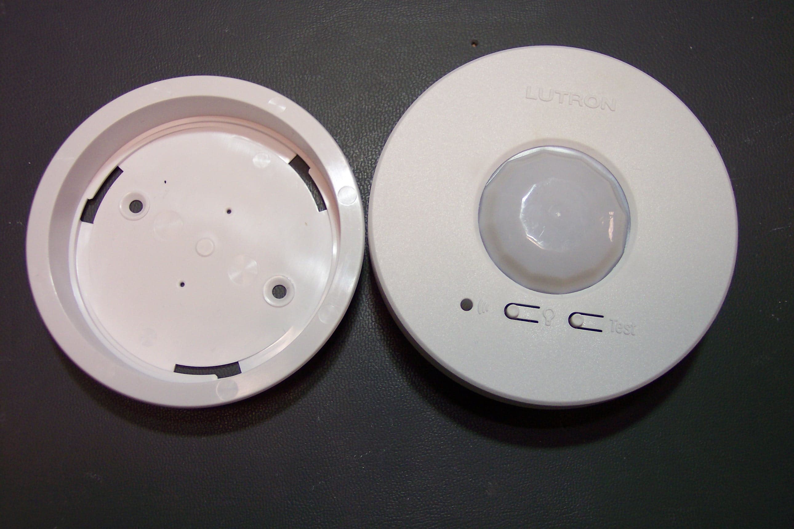
Click to zoom
Application Details
- Equipment Class
- DSC - Part 15 Security/Remote Control Transmitter
- Date of Grant
- Apr 19, 2011
- Application Purpose
- Original Equipment
- Date of Application
- Apr 19, 2011
- Equipment Note
- Occupancy/Vacancy Sensor
- Frequency Range
- 431.00000000 - 437.00000000
- Country
- United States
Documents & Files
Document Text
Text extracted from the exhibit documents filed with the FCC. Open a document above to read the original.
Users Manual
2.32.4 Key Features· Low Maintenance . 10-year battery life. Convenient low-battery indicator. · Multiple Devices. Up to 3 Sensors can work together to control lights for broader coverage in large spaces. Each Sensor may be added to a maximum of 10 receiving devices. Sensor Operation Occupancy Version – The Sensor will automatically turn the lights on when the space is occupied and automatically turn the lights off after the space is vacated. Vacancy-Only Version – The lights must be manually turned on* at the dimming or switching device. The Sensor will automatically turn the lights off after the space is vacated. * There is a built-in 15-second vacancy grace period that begins when the lights are automatically turned off, during which the lights will automatically turn back on in response to motion. This grace period is provided as a safety and convenience feature in the event that the lights turn off while the room is still occupied, so that the user does not need to manually turn the lights back on. After 15 seconds, the grace period expires and the lights must be manually turned on. NOTE: For either Sensor version, the lights can also be manually turned off at any time by using the dimming or switching device directly. B A Lutron Electronics Co., Inc.7200 Suter RoadCoopersburg, PA 18036-1299, U.S.A.Printed in the U.S.A. 07/10 P/N 041-272 Rev. B Important Notes1. This Sensor is part of a system and cannot be used to control a load without a compatible dimming or switching device. Refer to the instruction sheets of the receiving device(s) for installation information. 2. Clean Sensor with a soft damp cloth only. DO NOT use any chemical cleaners. 3. The Sensor is intended for indoor use only. Operate between 32 °F and 104 °F (0 °C and 40 °C). 4. DO NOT paint Sensor. 5. Use only high-quality lithium batteries, size CR123, 3 V (ANSI-5018LC, IEC- CR17345). DO NOT use rechargeable batteries. Using improperly rated batteries could damage the Sensor. NOTICE: DO NOT disassemble, crush, puncture, or incinerate batteries. DO NOT dispose of batteries in normal household waste. Please recycle, take to a proper battery disposal facility, or contact your local waste disposal provider regarding local restrictions on the disposal or recycling of batteries. 6. The range and performance of the RF system is highly dependent on a variety of complex factors such as: · Distance between system components · Geometry of the building structure · Construction of walls separating system components · Electrical equipment located near system components WARNING: Entrapment hazard. To avoid the risk of entrapment, serious injury, or death, these controls must not be used to control equipment which is not visible from every control location or which could create hazardous situations such as entrapment if operated accidentally. Examples of such equipment which must not be operated by these controls include (but are not limited to) motorized gates, garage doors, industrial doors, microwave ovens, heating pads, etc. It is the installer’s responsibility to ensure that the equipment being controlled is visible from every control location and that only suitable equipment is connected to these controls. Failure to do so could result in serious injury or death. 12 Removing Temporary Mounting Strip Remove the Sensor from the mounting bracket by twisting in a counter-clockwise direction.If the Sensor coverage and wireless communication tests have been successfully completed, use the mounting bracket as a template to mark the screw hole locations with a pencil. 3.1 Temporary Mounting: Solid CeilingUse this procedure if the Sensor will be mounted on a solid, continuous ceiling surface such as drywall, plaster, concrete, or wood. One 3M ™ Command ™ adhesive strip is provided for temporarily mounting and testing the Sensor on smooth, solid ceiling surfaces. This strip is designed for easy, damage-free removal and is not reusable. This strip should not be used for permanently mounting the Sensor (see section G. Permanent Mounting Methods ). Carefully follow the removal instructions below to ensure the ceiling is not damaged during removal. NOTE: DO NOT use the adhesive strip on ceiling tiles, as it will likely cause damage to the tile upon removal. Peel the red “Command Strips” liner off and apply to the fl at side of the mounting bracket as shown in the diagram. Press fi rmly. NOTE: DO NOT cover the bracket’s screw holes because they will be used to mark screw hole locations on the ceiling.NOTE: Leave the removal tab exposed past the edge of the bracket so it can be accessed for removal later. Identify a location on the ceiling where the Sensor will have a good view of the room.Remove the black “wall side” liner from the adhesive strip. Position the mounting bracket on a clean, dry, dust-free ceiling and press fi rmly for several seconds.Attach the Sensor to the mounting bracket by inserting and twisting in a clockwise direction until the Sensor locks into place. Perform the Sensor coverage and wireless communication tests as described in sections E. Testing Sensor Coverage and F. Testing Wireless Communication . 2.1 2.2 2.52.6 To remove the bracket from the ceiling, grasp the removal tab on the adhesive strip and pull the tab VERY SLOWLY straight across the ceiling, stretching the strip until the bracket releases from the ceiling. Discard the strip. NEVER pull the strip at an angle, as it may break or damage the ceiling surface. • Easy-to-follow Instructions P/N 041-272B Limited Warranty(Valid only in U.S.A., Canada, Puerto Rico, and the Caribbean.)Lutron will, at its option, repair or replace any unit that is defective in materials or manufacture within one year after purchase. For warranty service, return unit to place of purchase or mail to Lutron at 7200 Suter Rd., Coopersburg, PA 18036-1299, postage pre-paid.THIS WARRANTY IS IN LIEU OF ALL OTHER EXPRESS WARRANTIES, AND THE IMPLIED WARRANTY OF MERCHANTABILITY IS LIMITED TO ON…
Text truncated - open the document above for the full version.
Users Manual
Specification Submittalpage Job Name: Job Number: Model Numbers: Radio Powr SavrTMWireless Occupancy and Vacancy Sensors 369432 Rev A 1 04.08.11 Wireless Ceiling Mount Sensor Lutron’s ceiling-mounted occupancy/vacancy sensors are wireless, battery-powered passive infrared (PIR) sensors that automatically control lights via RF communication to compatible dimming and switching devices. These sensors detect the heat from people moving within an area to determine when the space is occupied. The sensors then wirelessly transmit the appropriate commands to the associated dimming and switching devices to turn the lights on or off automatically. They combine both convenience and exceptional energy savings along with ease of installation. Features • Wireless occupancy sensor has 3 settings available: Auto-On/Auto-Off, Auto-On Low-Light/Auto-Off, and Manual-On/Auto-Off • Auto-On Low-Light feature will only turn lights on automatically if there is less than approximately 1 fc (10 lux) of ambient light • Vacancy model available to meet CA Title 24 requirements • 10-year battery life design • Passive infrared motion detection with exclusive Lutron XCT TM Technology for fine motion detection • 360 ̊ coverage ranges from 324 sq ft (98 m() to 676 sq ft (206 m() (depending on mounting height) • Multiple ceiling-mount methods available for different ceiling materials • RoHS compliant • Simple and intuitive adjustments available for Timeout, Auto-On, and Activity settings • Front accessible test buttons make setup easy • Lens illuminates during test mode to verify ideal locations • Multiple sensors can be added for extended coverage— refer to product specification submittal of receiving device to determine system limits Compatible RF Devices: • For use with Lutron ® products only • Communicates to the following wireless Lutron systems: - Maestro ® Wireless® (MRF2) - GRAFIK Eye® QS Wireless - Energi Savr NodeTM QS (with QS Sensor Module on QS Link) - Quantum ® (with QS Sensor Module on QS Link) - RadioRA® 2 - HomeWorks® QS Models Available: • LRF2-OCR2B-P-WH* 434 MHz Occupancy/Vacancy Sensor • LRF2-VCR2B-P-WH* 434 MHz Vacancy Sensor *WH (white) Specification Submittalpage Job Name: Job Number: Model Numbers: Radio Powr SavrTMWireless Occupancy and Vacancy Sensors 369432 Rev A 2 04.08.11 3.57 in (9 0. 7mm) 1.13 in (28.7 mm) 0.887 in (22.5 mm) 2.85 in (72.4 mm) Specifications Standards • FCC certified • IC certified • COFETEL certified • RoHS compliant Environment • Temperature: 32 ̊F to 104 ̊F (0 ̊C to 40 ̊C) • For indoor use only Power • Operating voltage: 3 V - • Operating current: 14 μA nominal • Requires one CR 123 lithium battery • 10-year battery life design • Non-volatile memory (saved changes are stored during power loss) Sensor Coverage Test • Front accessible test button • Lens illuminates orange in response to motion during test mode and is visible from 60 ft (18 m) Wireless Communication Test • Front accessible test button • Turn loads on and off Timeout Options • 1 minute * • 5 minutes • 15 minutes ** • 30 minutes Auto-On Options (Occupancy Version Only) • “Always” ** - Sensor turns lights ON and OFF auto- matically. • “Low light” - Sensor turns lights ON automatically only in low ambient light conditions. Sensor turns lights OFF automatically. • “Disable” - Lights must be turned ON manually from dimming or switching device. Sensor turns lights OFF automatically. Activity Options • Low Activity ** ( ) • Medium Activity ( ) • High Activity ( ) ** - intended for use in high-activity, briefly occupied areas only * - default settings Dimensions Specification Submittalpage Job Name: Job Number: Model Numbers: Radio Powr SavrTMWireless Occupancy and Vacancy Sensors 369432 Rev A 3 04.08.11 Range Diagrams Sensor Coverage with an 8 ft (2.4 m) Ceiling 15 ft (4.6 m) 12 ft (3.7 m) 9 ft (2.7 m) 6 ft (1.8 m) 3 ft (0.9 m) 0 ft (0 m) 3 ft (0.9 m) 6 ft (1.8 m) 9 ft (2.7 m) 12 ft (3.7 m) 15 ft (4.6 m) Radius of Coverage at Floor Sensor Occupant 18 x 18 ft (5.5 x 5.5 m) Maximum Room Dimensions for Complete Coverage when mounted on an 8 ft (2.4 m) Ceiling 13 ft (4.0 m) Radius of Coverage at Floor when mounted on an 8 ft (2.4 m) Ceiling Ceiling Floor 8 ft (2.4 m) Ceiling height Instructions Sensor Coverage Chart (for sensor mounted in center of room) Ceiling height Maximum room dimensions for complete floor coverageSquare feet 8 ft (2.4 m)18 × 18 ft (5.5 × 5.5 m)324 ft 2 (30.2 m 2 ) 9 ft (2.7 m)20 × 20 ft (6.1 × 6.1 m)400 ft 2 (37.2 m 2 ) 10 ft (3.0 m)22 × 22 ft (6.7 × 6.7 m)484 ft 2 (44.9 m 2 ) 12 ft (3.7 m)26 × 26 ft (7.9 × 7.9 m)676 ft 2 (62.4 m 2 ) * Multiple sensors can be added for extended coverage—refer to product specification submittal of receiving device to determine system limits. Specification Submittalpage Job Name: Job Number: Model Numbers: Radio Powr SavrTMWireless Occupancy and Vacancy Sensors 369432 Rev A 4 04.08.11 Installation Overview Sensor Placement • The sensor’s ability to detect motion requires line of sight of room occupants. The sensor must have an unob- structed view of the room. DO NOT mount behind or near tall cabinets, shelves, hanging fixtures, ceiling fans, etc. The sensor cannot see through glass objects such as patio or shower doors. • Hot objects and moving air currents can affect the sensor’s performance. To ensure proper operation, the sen- sor should be mounted at least 4 ft (1.2 m) away from light bulbs below the ceiling line and HVAC vents. • The sensor’s performance depends on a temperature differential between the ambient room temperature and that of room occupants. Warmer rooms may reduce the sensor’s ability to detect occupants. • The sensor should be mounted within 60 ft (18 m) line of sight or 30 ft (9.1 m) through walls, of the associated dimming and switching receiving devices. Mounting • Mounting of any RF devices on or in close proximity to a metal surface (e.g. directly on fixture with metal housing, metal-backed ceiling tile) will drastically reduce the effectiv…
Text truncated - open the document above for the full version.
Block Diagram
Wire Monpole Micro-Controller RF Transmitter Buttons Laser Detect Ambient Light Detect PIR Sensor 1 2 3 1 26 MHz crystal oscillator 2 Carrier frequency between 431-437MHz 3 1MHz SPI interface, 541kHz clock 4 8MHz clock (active), 38kHz low speed oscillator (sleep) 4 Frequency Table 3.3VDC Power Supply Occupancy Sensor Block Diagram Crystal Oscillator
Test Report
Underwriters Laboratories Inc. A not-for-profit organization dedicated 1285 Walt Whitman Rd. to public safety and committed to Melville, NY 11747 quality service for over 100 years Tel: (631) 271-6200 Fax: (631)439-6095 Underwriters Laboratories Inc. 1285 Walt Whitman Rd. Melville, NY 11747 www.ul.com/emc (631) 271-6200 Job Number: 1001354517 Project Number: 11CA14767 File Number: MC15896 Date: 2011-04-13 Model: LRF2-OCR2B-P-XX FCC ID: JPZ0079 IC ID: 2851A-JPZ0079 Electromagnetic Compatibility Test Report For LUTRON ELECTRONICS INC Copyright 2010 Underwriters Laboratories Inc. Underwriters Laboratories Inc. authorizes the above-named company to reproduce this Report provided it is reproduced in its entirety. Job Number: 1001354517 File Number: MC15896 Page 2 of 35 Model Number: LRF2-OCR2B-P-XX Client Name: LUTRON ELECTRONICS INC FCC ID: JPZ0079 IC ID: 2851A-JPZ0079 Underwriters Laboratories Inc. 1285 Walt Whitman Rd. Melville, New York 11747 USA Tel.: 631 271-6200 Fax: 631 439-6095 Rev. No 1.0 EMC Report 2010-87-EM-F0042 Test Report Details Tests Performed By: Underwriters Laboratories Inc. 1285 Walt Whitman Rd. Melville, NY 11747 Tests Performed For: LUTRON ELECTRONICS INC 7200 SUTTER ROAD COOPERBURG, PA 18036 Applicant Contact: Steve O'Donnell Title: Senior Technician Phone: (610) 282-7342 E-mail: [email protected] Test Report Date: 2011-04-13 Product Type: Occupancy Sensor Product standards FCC Part 15, Subpart B, FCC Part 15 Subpart C, RSS-GEN, RSS-210 Model Number: LRF2-OCR2B-P-XX Sample Serial Number: Non-serialized production unit EUT Category: Periodic Low Power Transmitter Testing Start Date: 2011-03-28 Date Testing Complete: 2011-04-12 Overall Results: Compliant Underwriters Laboratories Inc. reports apply only to the specific samples tested under stated test conditions. All samples tested were in good operating condition throughout the entire test program. It is the manufacturer's responsibility to assure that additional production units of this model are manufactured with identical electrical and mechanical components. Underwriters Laboratories Inc. shall have no liability for any deductions, inferences or generalizations drawn by the client or others from Underwriters Laboratories Inc. issued reports. This report shall not be used to claim, constitute or imply product certification, approval, or endorsement by NVLAP, NIST, A2LA, or any agency of the US government. This report may contain test results that are not covered by the NVLAP or A2LA accreditation. The scope of accreditation is limited to the specific tests that are listed on the NVLAP and/or A2LA websites referenced at the end of this report. Job Number: 1001354517 File Number: MC15896 Page 3 of 35 Model Number: LRF2-OCR2B-P-XX Client Name: LUTRON ELECTRONICS INC FCC ID: JPZ0079 IC ID: 2851A-JPZ0079 Underwriters Laboratories Inc. 1285 Walt Whitman Rd. Melville, New York 11747 USA Tel.: 631 271-6200 Fax: 631 439-6095 Rev. No 1.0 EMC Report 2010-87-EM-F0042 Report Directory 1.0 G E N E R A L - Product Description ..................................................................................................................4 1.1 Equipment Description ...................................................................................................................................4 1.2 Equipment Marking Plate ...............................................................................................................................4 1.3 Device Configuration During Test ..................................................................................................................5 1.3.1 Equipment Used During Test: ....................................................................................................................5 1.3.2 Input/Output Ports: .....................................................................................................................................5 1.3.3 EUT Internal Operating Frequencies: ........................................................................................................6 1.3.4 Power Interface: .........................................................................................................................................6 1.4 Block Diagram: ...............................................................................................................................................7 1.5 EUT Configurations ........................................................................................................................................8 1.6 EUT Operation Modes ....................................................................................................................................8 2.0 Summary ............................................................................................................................................................9 2.1 Deviations from standard test methods ..........................................................................................................9 2.2 Device Modifications Necessary for Compliance ...........................................................................................9 2.3 Reference Standards .................................................................................................................................. 10 2.4 Results Summary ........................................................................................................................................ 10 3.0 Calibration of Equipment Used for Measurement ........................................................................................... 11 4.0 EMISSIONS TEST RESULTS ......................................................................................................................... 11 4.1 Test Conditions and Results – Occupied Bandwidth .................................................................................. 12 4.2 Test Conditions and Results – Cease Operatio…
Text truncated - open the document above for the full version.
Test Setup Photos
Job Number: 1001354517 File Number: MC15896 Page 13 of 35 Model Number: LRF2-OCR2B-P-XX Client Name: LUTRON ELECTRONICS INC FCC ID: JPZ0079 IC ID: 2851A-JPZ0079 Underwriters Laboratories Inc. 1285 Walt Whitman Rd. Melville, New York 11747 USA Tel.: 631 271-6200 Fax: 631 439-6095 Rev. No 1.0 EMC Report 2010-87-EM-F0042 Figure 1 Test Setup for Occupied Bandwidth Job Number: 1001354517 File Number: MC15896 Page 17 of 35 Model Number: LRF2-OCR2B-P-XX Client Name: LUTRON ELECTRONICS INC FCC ID: JPZ0079 IC ID: 2851A-JPZ0079 Underwriters Laboratories Inc. 1285 Walt Whitman Rd. Melville, New York 11747 USA Tel.: 631 271-6200 Fax: 631 439-6095 Rev. No 1.0 EMC Report 2010-87-EM-F0042 Figure 3 Test Setup for Cease Operation Job Number: 1001354517 File Number: MC15896 Page 20 of 35 Model Number: LRF2-OCR2B-P-XX Client Name: LUTRON ELECTRONICS INC FCC ID: JPZ0079 IC ID: 2851A-JPZ0079 Underwriters Laboratories Inc. 1285 Walt Whitman Rd. Melville, New York 11747 USA Tel.: 631 271-6200 Fax: 631 439-6095 Rev. No 1.0 EMC Report 2010-87-EM-F0042 Figure 5 Test Setup for Pulse Train Job Number: 1001354517 File Number: MC15896 Page 25 of 35 Model Number: LRF2-OCR2B-P-XX Client Name: LUTRON ELECTRONICS INC FCC ID: JPZ0079 IC ID: 2851A-JPZ0079 Underwriters Laboratories Inc. 1285 Walt Whitman Rd. Melville, New York 11747 USA Tel.: 631 271-6200 Fax: 631 439-6095 Rev. No 1.0 EMC Report 2010-87-EM-F0042 Figure 7 Test setup for Radiated Emissions
Contact Information
Applicant
Daniel Schlegel(Standards Compliance Supervisor)
Technical Contact
Underwriters Laboratories Inc.Bob DeLisi
[email protected]631-546-2452
1285 Walt Whitman Rd. · Melville, New York · United States
Non-Technical Contact
Underwriters Laboratories Inc.Bob DeLisi
[email protected]631-546-2452
Test Firm
UL LLCBob Delisi
Technical Specifications
| # | Rule Parts | Frequency Range | Power Output |
|---|---|---|---|
| 1 | 15.231 | 431 MHz - 437 MHz | - |
Other Applications from Lutron Electronics Company Inc
JPZ0161
Sep 03, 2026Wireless Interface
Equipment Class
DTS - Digital Transmission SystemJPZ0159
Aug 12, 2026Wireless Processor
Equipment Class
DTS - Digital Transmission SystemJPZ0158
Jul 27, 2026Copy of Wireless Processor
Equipment Class
DTS - Digital Transmission SystemJPZ0157
Mar 26, 2026LED Downlight
Equipment Class
DTS - Digital Transmission SystemJPZ0155
Sep 30, 2024LED Lighting Controller
Equipment Class
DTS - Digital Transmission System