JPZ0084Residential Room Thermostat
Lutron Electronics Company Inc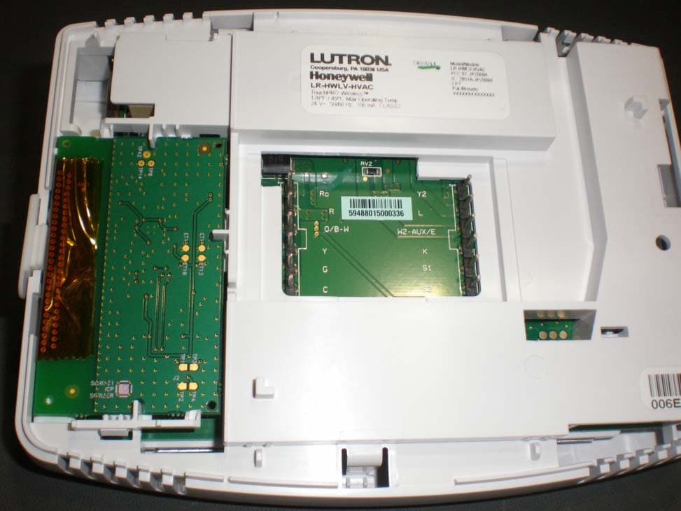
Click to zoom
Application Details
- Equipment Class
- DSR - Part 15 Remote Control/Security Device Transceiver
- Date of Grant
- Sep 27, 2011
- Application Purpose
- Original Equipment
- Date of Application
- Sep 27, 2011
- Equipment Note
- Residential Room Thermostat
- Frequency Range
- 431.00000000 - 437.00000000
- Country
- United States
Documents & Files
Document Text
Text extracted from the exhibit documents filed with the FCC. Open a document above to read the original.
Users Manual
© 2009 Lutron Electronics Co., Inc. Lutron Electronics Co., Inc. 7200 Suter Road Coopersburg, PA 18036 Made and printed in the U.S.A. Hecho e impreso en los E.U.A. Réalisé et imprimé aux Etats-Unis Editado e impresso nos E.U.A. 9 / 09 P/N 043-276 Rev. A English For installation instructions and warranties in different lan- guages, please go to the link below: Español Si desea instrucciones y garantías de instalación en otros idiomas, visite el siguiente enlace: Français Pour obtenir des instructions d’installation et garanties dans d’autres langues, veuillez utiliser le lien suivant : Português Para obter instruções de instalação e garantias noutros idiomas, visite: Deutsch Installationsanweisungen und Garantien in verschiedenen Sprachen finden Sie unter: Nederlands Ga voor installatie-instructies en garanties in andere talen naar de koppeling hier onder: Italiano Per le istruzioni d’installazione e le garanzie in una lingua diversa, selezionare il link sottostante: www.lutron.com/resiinfo Limited Warranty Garantie Limitée GarantÍa Limitada Garantia Limitada GarantÍa Limitada Exclusivamente en el caso de México ESPAÑOL PÓLiZa de GarantÍa LUTRON CN, S. de R.L. de C.V., RFC: LCN020626TD1, GABRIEL MANCERA 1041, COL. DEL VALLE 03100, MÉXICO D.F., MÉXICO, Tel. +1.888.235.2910 o +1.610.282.6701, garantiza todas las piezas y servicio de este producto por cualquier defecto de fabricación que exista y la eficiencia del mismo durante un (1) año, considerado a partir de la fecha de entrega o de instalación del producto, bajo las siguientes: CondiCiones: 1. Para hacer efectiva esta garantía, las reclamaciones no se podrán hacer si no es presentando esta póliza y el producto defectuoso en el lugar donde se compró el producto, en cualquira de los centros de servicio que se indican más adelante. El consumidor tambien podra comprar partes, componentes, consumibles y accesorios en dicho lugar. 2. LUTRON reemplazará o intercambiará el producto defectuoso sin hacer más cargos al cliente. Los gastos de transporte (si los hubiera) los cubrirá LUTRON CN, S. de R.L. de C.V. 3. El tiempo para reemplazar el producto no excederá de treinta (30) días, contados a partir del momento en que se reciba el producto en cualquiera de los lugares en donde esta garantía se pueda hacer efectiva. 4. Cuando se necesite hacer efectiva esta garantía reemplazando el producto, el trámite se hará en LUTRON CN, S. de R.L. de C.V. 5. Esta garantía perderá su validez en los casos siguientes: (A) Cuando el producto se haya usado en condiciones que no sean las normales. (B) Cuando el producto se haya hecho funcionar sin seguir las instrucciones del producto que vienen en español. (C) Cuando alguna(s) persona(s), no autorizada(s) por LUTRON CN, S. de R.L. de C.V., haya(n) alterado o reparado el producto. 6. El cliente podrá solicitar que esta póliza se haga efectiva en el establecimiento comercial donde se compró el producto. 7. En caso de que esta garantía se extravíe, el cliente podrá solicitar otra póliza de garantía al proveedor una vez que presente el recibo o factura de compra. NOMBRE: COL.: CIUDAD: ESTADO: TELÉFONO: DIRECCIÓN: C.P.: NOMBRE COMERCIAL: MARCA: NO. DE SERIE: NO. DE DISTRIBUIDOR: DIRECCIÓN: COL.: CIUDAD: ESTADO: TELÉFONO: FECHA DE VENTA: FECHA DE ENTREGA O DE INSTALACIÓN: PRODUCTO: MODELO: C.P.: inFormaCiÓn deL ConsUmidor inFormaCiÓn deL estaBLeCimiento o Vendedor PORTUGUÊS Sujeita às exclusões descritas abaixo, durante um período (definido abaixo) após a data de remessa por parte da Lutron, a Lutron garante que cada novo produto (“Produto”) estará isento de defeitos de fabricação. A Lutron, a seu critério, reparará a peça defeituosa ou fornecerá as peças de substituição comparáveis, desde que a Lutron seja prontamente notificada do defeito dentro do período de garantia (definido abaixo). As peças de substituição fornecidas pela Lutron podem ser novas, usadas, reparadas, recondicionadas e/ou feitas por um fabricante diferente. eXCLUsÕes da Garantia Limitada Esta Garantia não cobre e nem a Lutron e seus fornecedores serão responsáveis por: 1. Dano, mau funcionamento ou inoperabilidade diagnosticados pela Lutron ou terceiros aprovados pela Lutron causados pelo desgaste normal, mau uso, uso exces- sivo, instalação correta, negligência, acidente ou interferência das fontes de infravermelho ou freqüência de rádio ou obstáculos, tais como, entre outros, (a) uso de voltagens de linha, fusíveis e disjuntores incorretos; (b) falha na instalação, manutenção e operação do Produto em conformidade com as instruções operacionais fornecidas pela Lutron e as disposições aplicáveis do Código Elétrico Nacional dos EUA e das Normas de Segurança dos Underwriter’s Laboratories; (c) uso de aparelhos ou acessórios incompatíveis; (d) falha na manutenção do equipamento sob a temperatura ambiente especificada; (e) reparos ou ajustes não autoriza- dos; (f) vandalismo; e (g) um caso fortuito, como incêndio, relâmpago, inundação, tornado, terremoto, furacão ou outros problemas fora do controle da Lutron. 2. Custo de mão-de-obra no local para diagnosticar questões e remover, reparar, substituir, ajustar, reinstalar e/ou reprogramar o Produto, a critério da Lutron, sendo todos os custos pagos pelo Cliente ao preço atual do serviço. 3. Quando aplicável, os componentes e os equipamentos externos do Produto, como, lâmpadas, lastros que não sejam da Lutron, soquetes e acessórios; cabeamento do acessório entre os lastros e as lâmpadas; cabeamento das instalações entre os redutores de luz ou painéis do redutor de luz e lâmpadas e entre os controles, redutores de luz ou painéis do redutor de luz; e outros equipamentos dos fabricantes não fornecidos pela Lutron, como relógios, equipamentos audiovisuais, detectores de movimento, fotossensores, sensores de entrada para carros, almofadas de pressão, persianas e banheiras. 4. O custo de reparar ou substituir outras propriedades que tenham sido danificadas quando o produto não funciona corretamente, mesmo que o …
Text truncated - open the document above for the full version.
Users Manual
LR-HWLV-HVAC TouchPRO Wireless ™ Touchscreen Thermostat ® U.S. Registered Trademark. Copyright © 2011 Honeywell International Inc. All rights reserved. Installation Guide 69-2655EFS-01 System Types • Gas, oil, or electric heat with air conditioning • Warm air, hot water, high efficiency furnaces, heat pumps, steam, gravity • Heat only — including power to open and close zone valves (Series 20), and normally open zone valves • Heat only with fan • Cool only • 750 mV heating systems This thermostat contains a Lithium battery which may contain Perchlorate material. Perchlorate Material—special handling may apply, See www.dtsc.ca.gov/hazardouswaste/perchlorate MERCURY NOTICE This thermostat does not contain mercury. However, do not place your old thermostat in the trash if it contains mercury in a sealed tube. Contact the Thermostat Recycling Corporation at www. thermostat-recycle.org or 800.238.8192 for information on how and where to properly and safely dispose of your old thermostat. CAUTION: SHOCK HAZARD Can cause electrical shock or equipment damage. If not avoided, could result in minor or moderate personal injury. Disconnect power before beginning installation or servicing. Technical Assistance | 24 hours a day, 7 days a week | www.lutron.com U.S.A. / Canada: 1.800.523.9466 | Mexico: +1.888.235.2910 Other Countries: +1.610.282.3800 Warranty: For warranty information, please see the Warranty enclosed with the product, or visit www.lutron.com/resiinfo Installation Guide P/N 041-338 Rev. A 2 69-2655EFS—01 M33026 Wallplate installation 1. Separate wallplate from thermostat. 2. Mount wallplate as shown below. Drill 3/16 in (5 mm) holes for drywall. Drill 7/32 in (6 mm) holes for plaster. Wall anchors Wire holeMounting screws Grasp top and bottom of wallplate and pull to remove from thermostat. + + + M29480 RF Device Placement • The thermostat must be within 30 ft (9 m) of an RF signal repeater. CAUTION Thermostat should be installed by a climate control specialist to avoid damage to the equipment. TouchPRO Wireless ™ P/N 041-338 Rev. A 3 69-2655EFS—01 M32680 M32689 K W2 K E/AUX S1 S2 S1 S2 M32690 M32688 KK E/AUX S1 S2 S1 S2 Battery Replacement Push excess wire back into the wall opening. Plug wall opening with non-flammable insulation. Remove factory-installed jumper only for two-transformer systems. Wiring Connect the common side of the transformer to “C” terminal. This connection is mandatory. Power Requirements The TouchPRO Wireless thermostat has a coin cell battery that retains the time and date during a power failure. Under normal circumstances the coin cell should last five years. Should the time and date need to be reset after a power failure, this is an indication that the coin cell needs to be replaced. You should replace the battery every five years, or before leaving home for an extended period. Remove tab. The TouchPRO Wireless thermostat is shipped from the factory with the coin cell installed. To keep the battery from discharging during shipment and storage, the TouchPRO Wireless thermostat is shipped with a plastic tab inserted in the battery holder. This tab must be removed during installation. Simply pull the plastic tab out of the battery tray. Make sure that the battery tray is fully inserted into the TouchPRO Wireless thermostat. Coin cell battery tray To replace the battery, remove the battery tray using a screw driver. Place a new coin cell (type CR2032 or equivalent) observing the correct polarity and push the battery tray into the battery cover assembly. Installation Guide P/N 041-338 Rev. A 4 69-2655EFS—01 Wiring See [notes] below [1] Power supply. Provide disconnect means and overload protection as required. [3] Connection to 24 V common at the transformer is required. [5] O/B set to control as either O or B in installer setup. [6] If L terminal is used, 24 V common (terminal C) must be connected. [7] Heat pump reset (powered continuously when thermostat is set to Em. Heat mode; system monitor when set to Heat, Cool, or OFF). [9] See page 14 for more details. Terminal Designations Conventional Terminal Letters: R Heating power. Connect to secondary side of heating system transformer. Rc Cooling power. Connect to secondary side of cooling system transformer. C Common wire from secondary side of cooling transformer (if 2 transform- ers). [3] W 1st stage heat relay. W2 2nd stage heat relay Y 1st stage compressor contactor. Y2 2nd stage compressor contactor. G Fan relay. K Optional THP9045 Wiring Module Terminal [9] S1/S2 Optional remote sensor Heat Pump Terminal Letters: R Heating power. Connect to secondary side of heating system transformer. Rc Cooling power. Connect to secondary side of cooling system transformer. C Common wire from secondary side of cooling system transformer. [3] Y 1st stage compressor contactor. Y2 2nd stage compressor contactor. Aux/E Auxiliary heat relay. G Fan relay. L Heat pump reset (powered continu- ously when System is set to Em Heat; system monitor when set to Heat, Cool or Off). O/B Changeover valve for heat pumps. K Optional THP9045 Wiring Module Terminal [9] S1/S2 Optional remote sensor Wiring guide—heat pump systems 1H/1C Heat Pump (no auxiliary heat) Rc Power [1] R [R+Rc joined by jumper] O/B Changeover valve [5] Y Compressor relay G Fan relay C 24 V common [3] K Optional THP9045 Wiring Module Terminal [9] S1/S2 Optional remote sensor 2H/1C Heat Pump (with auxiliary heat) L Equipment monitor [6, 7] Aux/E Auxiliary heat relay (Heat 2) [8] Rc Power [1] R [R+Rc joined by jumper] O/B Changeover valve [5] Y Compressor relay G Fan relay C 24 V common [3] K Optional THP9045 Wiring Module Terminal [9] S1/S2 Optional remote sensor 2H/2C Heat Pump (no auxiliary heat) Y2 Compressor 2 relay Rc Power [1] R [R+Rc joined by jumper] O/B Changeover valve [5] Y Compressor 1 relay G Fan relay C 24 V common [3] K Optional THP9045 Wiring Module Terminal [9] S1/S2 Optional remote sensor 3H/2C Heat Pump (with auxiliary heat) Y2 Compressor 2 relay L Equi…
Text truncated - open the document above for the full version.
External Photos
LR‐HWLV‐HVAC Photos Front Back with mounting plate LR‐HWLV‐HVAC Photos Back Unit Label Lutron RF board.
ID Label/Location Info
LR‐HWLV‐HVAC Photos Back Unit Label Lutron RF board.
Internal Photos
LR‐HWLV‐HVAC Photos RF Board Front LR‐HWLV‐HVAC Photos RF Board Back
Test Setup Photos
1. SETUP PHOTOS ANTENNA PORT ANTENNA PORT RADIATED EMISSION ABOVE 30 MHz RADIATED EMISSIONS ABOVE 30 MHz (FRONT) RADIATED EMISSIONS ABOVE 30 MHz (BACK) AC MAINS LINE CONDUCTED EMISSION LINE CONDUCTED EMISSION (FRONT) END OF REPORT LINE CONDUCTED EMISSION (BACK)
Contact Information
Applicant
Daniel Schlegel(Standards Compliance Supervisor)
Technical Contact
Underwriters Laboratories Inc.Bob DeLisi
[email protected]631-546-2452
1285 Walt Whitman Rd. · Melville, New York · United States
Non-Technical Contact
Underwriters Laboratories Inc.Bob DeLisi
[email protected]631-546-2452
Test Firm
UL LLCBob Delisi
Technical Specifications
| # | Rule Parts | Frequency Range | Power Output |
|---|---|---|---|
| 1 | 15.231 | 431 MHz - 437 MHz | - |
Other Applications from Lutron Electronics Company Inc
JPZ0161
Sep 03, 2026Wireless Interface
Equipment Class
DTS - Digital Transmission SystemJPZ0159
Aug 12, 2026Wireless Processor
Equipment Class
DTS - Digital Transmission SystemJPZ0158
Jul 27, 2026Copy of Wireless Processor
Equipment Class
DTS - Digital Transmission SystemJPZ0157
Mar 26, 2026LED Downlight
Equipment Class
DTS - Digital Transmission SystemJPZ0155
Sep 30, 2024LED Lighting Controller
Equipment Class
DTS - Digital Transmission System