JPZ0086Wall Mount Sensor
Lutron Electronics Company Inc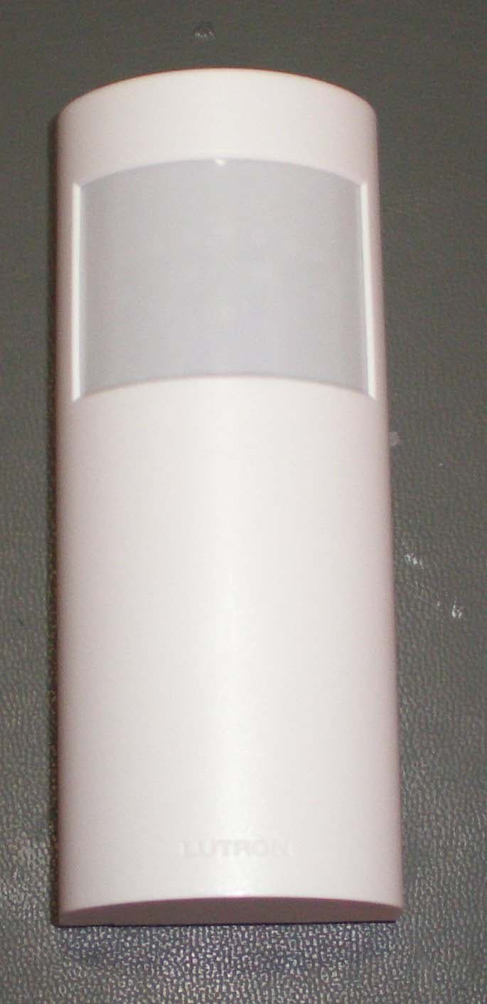
Click to zoom
Application Details
- Equipment Class
- DSC - Part 15 Security/Remote Control Transmitter
- Date of Grant
- Oct 20, 2011
- Application Purpose
- Original Equipment
- Date of Application
- Oct 20, 2011
- Equipment Note
- Wall Mount Sensor
- Frequency Range
- 431.00000000 - 437.00000000
- Country
- United States
Documents & Files
Document Text
Text extracted from the exhibit documents filed with the FCC. Open a document above to read the original.
Users Manual
Mounting Offset from a Corner In this procedure, the bracket’s screw hole and slot are used for mounting. Mark the screw hole locations with a pencil, using the mounting bracket as a template. Drill two 3/16 in (5 mm) pilot holes for the provided screw anchors. NOTE: If mounting on a plaster wall, you may wish to also clear out a larger area for the lip of the anchor by hand-turning a 3/8 in (9.5 mm) drill bit into the top of the pilot hole. Press the anchors into the holes and tap flush with a hammer. Place the mounting bracket against the wall and loosely install the two provided screws. Straighten the mounting bracket vertically and then tighten the screws fully. Mount the Sensor by sliding it down onto the mounting bracket until it clicks into place. Confirm the coverage area by walking through the space and observing the lens. The lens will glow solid every time motion is detected. If the lens remains off during motion, the Sensor cannot detect motion at that location. Press and release the “Test” button again to exit the test mode. If the button is not pressed, the test mode will automatically time out 15 minutes after being enabled, or 5 minutes after the last detected motion if the room is vacated. If the Sensor has significant trouble detecting motion during the test, it should be moved to another location and retested. If the Sensor still has poor detection from the new location, refer to the Troubleshooting section. If Sensor detection is satisfactory during this test, perform the wireless communication test as described in section F. Testing Wireless Communication. Removing Temporary Mounting Strip Remove the Sensor from the mounting bracket by sliding it up and off. If the Sensor coverage and wireless communication tests have been successfully completed, mark the location of the mounting bracket for permanent installation. Hold the bracket securely with one hand. With the other hand, grasp the removal tab on the adhesive strip and pull the tab VERY SLOWLY straight down the wall, stretching the strip until the bracket releases from the wall. Discard the strip. NEVER pull the strip at an angle, as it may break or damage the wall surface. Key Features · Low Maintenance 10-year battery life. Convenient low-battery indicator. · Multiple Devices. Multiple Sensors can work together to control lights for broader coverage in large spaces. In addition, each Sensor may be added to multiple receiving devices. Maximum number of allowed devices varies by system. Consult the Product Specification Submittal of the receiving device for system limits. Sensor Operation Occupancy Version – The Sensor will automatically turn the lights on when the space is occupied and automatically turn the lights off after the space is vacated. Vacancy-Only Version – The lights must be manually turned on* at the dimming or switching device. The Sensor will automatically turn the lights off after the space is vacated. * There is a built-in 15-second vacancy grace period that begins when the lights are automatically turned off, during which the lights will automatically turn back on in response to motion. This grace period is provided as a safety and convenience feature in the event that the lights turn off while the room is still occupied, so that the user does not need to manually turn the lights back on. After 15 seconds, the grace period expires and the lights must be manually turned on. NOTE: For either Sensor version, the lights can also be manually turned off at any time by using the dimming or switching device directly. B A Lutron Electronics Co., Inc. 7200 Suter Road Coopersburg, PA 18036-1299, U.S.A. P/N 041-364 Rev. A 10 / 2011 Important Notes 1. This Sensor is part of a system and cannot be used to control a load without a compatible dimming or switching device. Refer to the instruction sheets of the receiving device(s) for installation information. 2. Clean Sensor with a soft damp cloth only. DO NOT use any chemical cleaners. 3. The Sensor is intended for indoor use only. Operate between 32 °F and 104 °F (0 °C and 40 °C). 4. DO NOT paint Sensor. 5. Use only high-quality lithium batteries, size CR123, 3 V- (ANSI-5018LC, IEC-CR17345). DO NOT use rechargeable batteries. Using improperly rated batteries could damage the Sensor. NOTICE: DO NOT disassemble, crush, puncture, drop on a hard surface, subject to high heat, place in water, incinerate, or alter batteries in any way. Please dispose of batteries in compliance with all applicable legal requirements. Your waste disposal provider may have information regarding any state or local restrictions on battery disposal. 6. The range and performance of the RF system is highly dependent on a variety of complex factors such as: · Distance between system components · Geometry of the building structure · Construction of walls separating system components · Electrical equipment located near system components WARNING: Entrapment hazard. To avoid the risk of entrapment, serious injury, or death, these controls must not be used to control equipment which is not visible from every control location or which could create hazardous situations such as entrapment if operated accidentally. Examples of such equipment which must not be operated by these controls include (but are not limited to) motorized gates, garage doors, industrial doors, microwave ovens, heating pads, etc. It is the installer’s responsibility to ensure that the equipment being controlled is visible from every control location and that only suitable equipment is connected to these controls. Failure to do so could result in serious injury or death. 1 2 • Easy-to-follow Instructions P/N 041-350a Limited Warranty (Valid only in U.S.A., Canada, Puerto Rico, and the Caribbean.) Lutron will, at its option, repair or replace any unit that is defective in materials or manufacture within one year after purchase. For warranty service, return unit to place of purchase or mail to Lutron at 7200 Suter Rd., Coopersbur…
Text truncated - open the document above for the full version.
External Photos
JPZ0086 ‐ Photos
ID Label/Location Info
JPZ0086 ‐ Photos
Internal Photos
JPZ0086 ‐ Photos JPZ0086 ‐ Photos
Test Report
FCC CFR47 PART 15 SUBPART C INDUSTRY CANADA RSS-210 ISSUE 8 CERTIFICATION TEST REPORT FOR WALL MOUNT SENSOR MODEL NUMBER: LRF2-OHLB-P FCC ID: JPZ0086 IC: 2851A-JPZ0086 REPORT NUMBER: 1001418578 ISSUE DATE:2011-09-29 Prepared for LUTRON ELECTRONICS INC 7200 SUTTER ROAD COOPERBURG PA 18036, USA Prepared by UNDERWRITERS LABORATORIES INC. 1285 WALT WHITMAN RD. MELVILLE, NY 11747, U.S.A. TEL: (631) 271-6200 FAX: (877) 854-3577 REPORT NO: 1001418578 DATE: 2011-09-29 FCC ID: JPZ0086 IC: 2851A-JPZ0086 Page 2 of 31 UNDERWRITERS LABORATORIES INC. FORM NO: CCSUP4701D 1285 WALT WHITMAN RD, MELVILLE, NY 11747, USA TEL: (631) 271-6200 FAX: (877) 854-3577 This report shall not be reproduced except in full, without the written approval of Underwriters Laboratories Inc. Revision History Rev. Issue Date Revisions Revised By -- 2011- 09-29 Initial Issue B. DeLisi REPORT NO: 1001418578 DATE: 2011-09-29 FCC ID: JPZ0086 IC: 2851A-JPZ0086 Page 3 of 31 UNDERWRITERS LABORATORIES INC. FORM NO: CCSUP4701D 1285 WALT WHITMAN RD, MELVILLE, NY 11747, USA TEL: (631) 271-6200 FAX: (877) 854-3577 This report shall not be reproduced except in full, without the written approval of Underwriters Laboratories Inc. TABLE OF CONTENTS 1. ATTESTATION OF TEST RESULTS ................................................................................. 4 2. TEST METHODOLOGY ..................................................................................................... 5 3. FACILITIES AND ACCREDITATION ................................................................................. 5 4. CALIBRATION AND UNCERTAINTY ................................................................................ 5 4.1. MEASURING INSTRUMENT CALIBRATION .............................................................. 5 4.2. SAMPLE CALCULATION ............................................................................................ 5 4.3. MEASUREMENT UNCERTAINTY ............................................................................... 5 5. EQUIPMENT UNDER TEST ............................................................................................... 6 5.1. DESCRIPTION OF EUT .............................................................................................. 6 5.2. DESCRIPTION OF AVAILABLE ANTENNAS .............................................................. 6 5.3. SOFTWARE AND FIRMWARE .................................................................................... 6 5.4. WORST-CASE CONFIGURATION AND MODE .......................................................... 6 5.5. MODIFICATIONS ........................................................................................................ 6 5.6. DESCRIPTION OF TEST SETUP ................................................................................ 7 6. TEST AND MEASUREMENT EQUIPMENT ....................................................................... 8 7. ANTENNA PORT TEST RESULTS .................................................................................... 9 7.1. 20 dB AND 99% BW .................................................................................................... 9 7.2. DUTY CYCLE .............................................................................................................13 7.3. TRANSMISSION TIME ...............................................................................................16 8. RADIATED EMISSION TEST RESULTS...........................................................................18 8.1. TX RADIATED SPURIOUS EMISSION ......................................................................18 9. SETUP PHOTOS ...............................................................................................................29 REPORT NO: 1001418578 DATE: 2011-09-29 FCC ID: JPZ0086 IC: 2851A-JPZ0086 Page 4 of 31 UNDERWRITERS LABORATORIES INC. FORM NO: CCSUP4701D 1285 WALT WHITMAN RD, MELVILLE, NY 11747, USA TEL: (631) 271-6200 FAX: (877) 854-3577 This report shall not be reproduced except in full, without the written approval of Underwriters Laboratories Inc. 1. ATTESTATION OF TEST RESULTS COMPANY NAME: LUTRON ELECTRONICS INC 7200 SUTTER ROAD COOPERBURG, PA 18036, USA EUT DESCRIPTION: Wall Mount Sensor MODEL: LRF2-OHLB-P SERIAL NUMBER: Non-serialized production unit DATE TESTED: 2011-09-15 to 2011-09-20 APPLICABLE STANDARDS STANDARD TEST RESULTS FCC PART 15 SUBPART C Pass INDUSTRY CANADA RSS-210 Issue 8, Annex 1 Pass INDUSTRY CANADA RSS-GEN Issue 3 Pass Underwriters Laboratories Inc. tested the above equipment in accordance with the requirements set forth in the above standards, using test results reported in the test report documents referenced below and/or documentation furnished by the applicant. All indications of Pass/Fail in this report are opinions expressed by Underwriters Laboratories Inc. based on interpretations of these calculations. The results show that the equipment is capable of demonstrating compliance with the requirements as documented in this report. Note: The results documented in this report apply only to the tested sample, under the conditions and modes of operation, as described by the referenced documents. This document may not be altered or revised in any way unless done so by Underwriters Laboratories Inc. and all revisions are duly noted in the revisions section. Any alteration of this document not carried out by Underwriters Laboratories Inc. will constitute fraud and shall nullify the document. This report must not be used by the client to claim product certification, approval, or endorsement by NVLAP, NIST, any agency of the Federal Government, or any agency of any government. Approved & Released For UL By: Tested By: Joseph Danisi Bob DeLisi Lead Engineering Assoicate Sr. Staff Engineer UL UL REPORT NO: 1001418578 DATE: 2011-09-29 FCC ID: JPZ0086 IC: 2851A-JPZ0086 Page 5 of 31 UNDERWRITERS LABORATORIES INC. FORM NO: CCSUP4701D 1285 WALT WHITMAN RD, MELVILLE, NY 11747, USA TEL: (631) 271-620…
Text truncated - open the document above for the full version.
Test Setup Photos
1. SETUP PHOTOS ANTENNA PORT ANTENNA PORT RADIATED EMISSION ABOVE 30 MHz RADIATED EMISSIONS ABOVE 30 MHz (FRONT) END OF REPORT RADIATED EMISSIONS ABOVE 30 MHz (BACK)
Contact Information
Applicant
Daniel Schlegel(Standards Compliance Supervisor)
Test Firm
UL LLCRick Titus
Technical Specifications
| # | Rule Parts | Frequency Range | Power Output |
|---|---|---|---|
| 1 | 15.231 | 431 MHz - 437 MHz | - |
Other Applications from Lutron Electronics Company Inc
JPZ0161
Sep 03, 2026Wireless Interface
Equipment Class
DTS - Digital Transmission SystemJPZ0159
Aug 12, 2026Wireless Processor
Equipment Class
DTS - Digital Transmission SystemJPZ0158
Jul 27, 2026Copy of Wireless Processor
Equipment Class
DTS - Digital Transmission SystemJPZ0157
Mar 26, 2026LED Downlight
Equipment Class
DTS - Digital Transmission SystemJPZ0155
Sep 30, 2024LED Lighting Controller
Equipment Class
DTS - Digital Transmission System