JPZ0087Repeater
Lutron Electronics Company Inc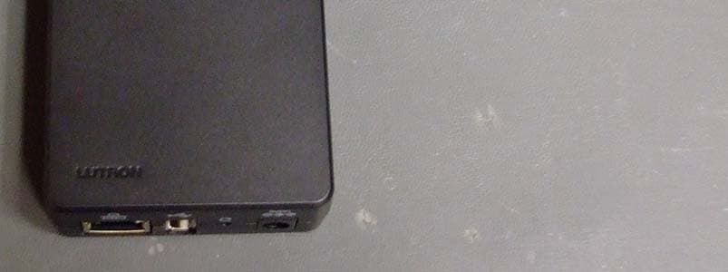
Click to zoom
Application Details
- Equipment Class
- DSR - Part 15 Remote Control/Security Device Transceiver
- Date of Grant
- Jan 12, 2012
- Application Purpose
- Original Equipment
- Date of Application
- Jan 12, 2012
- Equipment Note
- Repeater
- Frequency Range
- 431.00000000 - 437.00000000
- Country
- United States
Documents & Files
Document Text
Text extracted from the exhibit documents filed with the FCC. Open a document above to read the original.
Users Manual
Wall #6 (M3) screw recommended Vertical Horizontal 1.00 (25.4) Level Surface Features • Supports system setup and ensures error-free communication between system components. • Reset button returns the Clear ConnectT Translator to factory settings. •Ethernet port for integration and PC connectivity. •LED feedback for RF and Ethernet communication. • LED feedback for Power status. Important Notes Environment Ambient operating temperature: 32 °F to 104 °F (0 °C to 40 °C), 0% to 90% humidity, non-condensing. Indoor use only. Codes Install in accordance with all local and national electrical codes. Cleaning To clean, wipe with a clean damp cloth. DO NOT use any chemical cleaning solutions. DC Adapter Power NOTICE - Using a DC adapter not rated at the proper specifications could damage the Clear ConnectT Translator and possibly overheat the DC adapter. Use only the LutronR DC adapter listed above. RF Device Placement All dimmers, switches, keypads and shades / draperies must be located within 30 ft (9 m) of a Clear ConnectT Translator. Installation 1. Find a suitable location for the Clear ConnectT Translator. 2. Mount vertically or horizontally, as shown in the Mounting Diagram, using two #6 (M3) screws. When mounting, allow 7 in (177.8 mm) clearance for the antenna and ensure convenient access to the power plug. In order to achieve proper RF performance, do not mount unit in a metal enclosure. 3. Attach the DC adapter cord to the power jack on the Clear ConnectT Translator and insert the DC adapter plug into a receptacle. Dimensions Measurements are in inches (mm). Installation Instructions Please Read Before Installing Lutron Elec tron ics Co., Inc. 7200 Suter Road Coopersburg, PA 18036-1299 P/N 044-297 Rev. A 11/2011 English NEC is a registered trademark of National Fire Protection Association, Quincy, Massachusetts. Lutron and are registered trademarks and Clear Connect is a trademark of Lutron Electronics Co., Inc. © 2011 Lutron Electronics Co., Inc. Clear ConnectT Translator NXB-CCG 5 V 2 A DC Adapter: PS-5DC-20-BL Output: 5 V 2 A Typical Power Consumption*: 5 W Warranty: For warranty information, please see the Warranty enclosed with the product, or visit www.lutron.com/resiinfo Connection Mounting Diagram (side view) Power Jack (to DC adapter) (IEC PELV / NECR Class 2) (Model: PS-5DC-20-BL) CAT5 Cable: maximum 328 ft (100 m) (bottom view) RF range: To other devices 30 ft (9 m) (top view) 87654321 12345 6789 Ethernet Pin Numbering Ethernet Pin # T+Ve1 T-Ve2 R+Ve3 R-Ve6 * Typical Power Consumption test conditions: one LED on, Ethernet cable plugged in, Clear ConnectT Translator powered by the 5 V adapter supplied. Operation Clear ConnectT Translator RF Configuration 6.25 (158.8) 4.42 (112.3) 2.72 (69) 1.30 (33) 2.60 (66) 30 ft (9 m) maximum Reset Button Press and hold for 30 seconds to restore the system to the Factory settings. USB Cable: (Lutron use only) RF LED Displays the Tx / Rx activity on the RF link. Power/Status LED Displays power status and other system status indicators. Ethernet LED Displays the connection status and Tx / Rx activity on the Ethernet link. FCC/ IC Information This device complies with part 15 of the FCC Rules and Industry Canada license- exempt RSS standard(s). Operation is subject to the following two conditions: (1) This device may not cause interference, and (2) this device must accept any interference, including interference that may cause undesired operation. Modifications not expressly approved by Lutron Electronics Co., Inc. could void the user’s authority to operate this equipment. Note: This equipment has been tested and found to comply with the limits for a Class B digital device, pursuant to part 15 of the FCC Rules. These limits are designed to provide reasonable protection against harmful interference in a residential installation. This equipment generates, uses and can radiate radio frequency energy and, if not installed and used in accordance with the instructions, may cause harmful interference to radio communications. However, there is no guarantee that interference will not occur in a particular installation. If this equipment does cause harmful interference to radio or television reception, which can be determined by turning the equipment off and on, the user is encouraged to try to correct the interference by one or more of the following measures: —Reorient or relocate the receiving antenna. —Increase the separation between the equipment and receiver. — Connect the equipment into an outlet on a circuit different from that to which the receiver is connected. —Consult the dealer or an experienced radio/TV technician for help. Returning a Clear ConnectT Translator to Factory Settings Note: Returning a Clear ConnectT Translator to factory settings will erase all programming from it and all system devices and will require the Clear ConnectT Translator to be reprogrammed into the system. 1. Press and hold the Reset button on the Clear ConnectT Translator for 30 seconds. 2. The Power/Status LED will start flashing slowly for approximately 10 seconds after which it will start rapidly flashing for approximately 20 seconds and then remain on. 3. The Clear ConnectT Translator has been returned to factory settings.
External Photos
CCD-TRANS Photos CCD-TRANS Photos
Internal Photos
CCD-TRANS Photos CCD-TRANS Photos Figure 1: Internal with RF Board in place Figure 2: Internal with RF board removed CCD-TRANS Photos Figure 3: Back of board
Test Report
FCC CFR47 PART 15 SUBPART C INDUSTRY CANADA RSS-210 ISSUE 8 CERTIFICATION TEST REPORT FOR REPEATER MODEL NUMBER: CCD-TRANS FCC ID: JPZ0087 IC: 2851A-JPZ0087 REPORT NUMBER: 1001421784 ISSUE DATE:2011-12-20 Prepared for LUTRON ELECTRONICS INC 7200 SUTTER ROAD COOPERBURG PA 18036, USA Prepared by UNDERWRITERS LABORATORIES INC. 1285 WALT WHITMAN RD. MELVILLE, NY 11747, U.S.A. TEL: (631) 271-6200 FAX: (877) 854-3577 REPORT NO: 1001421784 DATE: 2011-12-20 FCC ID: JPZ0087 IC:2851A-JPZ0087 Page 2 of 58 UNDERWRITERS LABORATORIES INC. FORM NO: CCSUP4701D 1285 WALT WHITMAN RD, MELVILLE, NY 11747, USA TEL: (631) 271-6200 FAX: (877) 854-3577 This report shall not be reproduced except in full, without the written approval of Underwriters Laboratories Inc. Revision History Rev. Issue Date Revisions Revised By -- 2011- 12-20 Initial Issue B. DeLisi REPORT NO: 1001421784 DATE: 2011-12-20 FCC ID: JPZ0087 IC:2851A-JPZ0087 Page 3 of 58 UNDERWRITERS LABORATORIES INC. FORM NO: CCSUP4701D 1285 WALT WHITMAN RD, MELVILLE, NY 11747, USA TEL: (631) 271-6200 FAX: (877) 854-3577 This report shall not be reproduced except in full, without the written approval of Underwriters Laboratories Inc. TABLE OF CONTENTS 1. ATTESTATION OF TEST RESULTS ................................................................................. 4 2. TEST METHODOLOGY ..................................................................................................... 5 3. FACILITIES AND ACCREDITATION ................................................................................. 5 4. CALIBRATION AND UNCERTAINTY ................................................................................ 5 4.1. MEASURING INSTRUMENT CALIBRATION .............................................................. 5 4.2. SAMPLE CALCULATION ............................................................................................ 5 4.3. MEASUREMENT UNCERTAINTY ............................................................................... 5 5. EQUIPMENT UNDER TEST ............................................................................................... 6 5.1. DESCRIPTION OF EUT .............................................................................................. 6 5.2. DESCRIPTION OF AVAILABLE ANTENNAS .............................................................. 6 5.3. SOFTWARE AND FIRMWARE .................................................................................... 6 5.4. WORST-CASE CONFIGURATION AND MODE .......................................................... 6 5.5. MODIFICATIONS ........................................................................................................ 6 5.6. DESCRIPTION OF TEST SETUP ................................................................................ 7 6. TEST AND MEASUREMENT EQUIPMENT ......................................................................11 7. ANTENNA PORT TEST RESULTS ...................................................................................13 7.1. 20 dB AND 99% BW ...................................................................................................13 7.2. DUTY CYCLE .............................................................................................................17 7.3. TRANSMISSION TIME ...............................................................................................20 8. RADIATED EMISSION TEST RESULTS...........................................................................21 8.1. TX RADIATED SPURIOUS EMISSION ......................................................................21 8.2. RX RADIATED SPURIOUS EMISSION ......................................................................32 9. AC MAINS LINE CONDUCTED EMISSIONS ....................................................................41 10. SETUP PHOTOS ...........................................................................................................54 REPORT NO: 1001421784 DATE: 2011-12-20 FCC ID: JPZ0087 IC:2851A-JPZ0087 Page 4 of 58 UNDERWRITERS LABORATORIES INC. FORM NO: CCSUP4701D 1285 WALT WHITMAN RD, MELVILLE, NY 11747, USA TEL: (631) 271-6200 FAX: (877) 854-3577 This report shall not be reproduced except in full, without the written approval of Underwriters Laboratories Inc. 1. ATTESTATION OF TEST RESULTS COMPANY NAME: LUTRON ELECTRONICS INC 7200 SUTTER ROAD COOPERBURG, PA 18036, USA EUT DESCRIPTION: Repeater MODEL: CCD-TRANS SERIAL NUMBER: Non-serialized production unit DATE TESTED: 2011-09-21 through 2011-12-20 APPLICABLE STANDARDS STANDARD TEST RESULTS FCC PART 15 SUBPART C Pass INDUSTRY CANADA RSS-210 Issue 8, Annex 1 Pass INDUSTRY CANADA RSS-GEN Issue 3 Pass Underwriters Laboratories Inc. tested the above equipment in accordance with the requirements set forth in the above standards, using test results reported in the test report documents referenced below and/or documentation furnished by the applicant. All indications of Pass/Fail in this report are opinions expressed by Underwriters Laboratories Inc. based on interpretations of these calculations. The results show that the equipment is capable of demonstrating compliance with the requirements as documented in this report. Note: The results documented in this report apply only to the tested sample, under the conditions and modes of operation, as described by the referenced documents. This document may not be altered or revised in any way unless done so by Underwriters Laboratories Inc. and all revisions are duly noted in the revisions section. Any alteration of this document not carried out by Underwriters Laboratories Inc. will constitute fraud and shall nullify the document. This report must not be used by the client to claim product certification, approval, or endorsement by NVLAP, NIST, any agency of the Federal Government, or any agency of any government. Approved & Released For UL By: Tested By: Joseph Danisi Bob DeLisi Lead Engineering Assoicate Sr. Staff Engineer UL UL REPORT NO: …
Text truncated - open the document above for the full version.
Test Setup Photos
1. SETUP PHOTOS ANTENNA PORT ANTENNA PORT RADIATED EMISSION ABOVE 30 MHz RADIATED EMISSIONS ABOVE 30 MHz (FRONT) RADIATED EMISSIONS ABOVE 30 MHz (BACK) - TX AC MAINS LINE CONDUCTED EMISSION LINE CONDUCTED EMISSION (FRONT) END OF REPORT LINE CONDUCTED EMISSION (BACK)
Contact Information
Applicant
Daniel Schlegel(Standards Compliance Supervisor)
Test Firm
UL LLCRick Titus
Technical Specifications
| # | Rule Parts | Frequency Range | Power Output |
|---|---|---|---|
| 1 | 15.231 | 431 MHz - 437 MHz | - |
Other Applications from Lutron Electronics Company Inc
JPZ0161
Sep 03, 2026Wireless Interface
Equipment Class
DTS - Digital Transmission SystemJPZ0159
Aug 12, 2026Wireless Processor
Equipment Class
DTS - Digital Transmission SystemJPZ0158
Jul 27, 2026Copy of Wireless Processor
Equipment Class
DTS - Digital Transmission SystemJPZ0157
Mar 26, 2026LED Downlight
Equipment Class
DTS - Digital Transmission SystemJPZ0155
Sep 30, 2024LED Lighting Controller
Equipment Class
DTS - Digital Transmission System